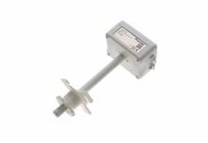
CDC-NA 2-10V Duct Humidity Sensor
Product Information: CDC-NA – 2-10V Duct Humidity Sensor
The CDC-NA – 2-10V Duct Humidity Sensor is a Condair duct
humidity sensor that can be configured for either humidity control
or as a high limit safety device. The kit includes Component No.
2597926 and Description No. 1509857, which is the 2-10V Duct
Humidity Sensor.
Product Usage Instructions:
- Refer to installation overview in section 2 of the user
manual. - At the place of location, drill a hole with a diameter of 16 mm
(5/8) as well as 4 holes for the self-tapping screws into the
duct. - Loosen the screw on the housing cover and open cover.
- Lead connecting cable through the cable gland and connect wires
to the terminate according to the wiring diagram. - Stick gasket on the sensor side centrally on the housing
(self-adhesive). - Insert the probe into the hole in the duct, then fix the
housing to the duct using the 4 self-tapping screws provided. - Close the cover and fix it with the screw (do not tighten the
screw too much).
Note: We recommend using 18-gauge wire, and maximum.
View Fullscreen
CDC-NA – 2-10V Duct Humidity Sensor
2-10V Duct Humidity Sensor Installation Instructions
This document covers the operation and installation instructions for the following Condair duct humidity sensor:
Kit No. Component No. Description
2597926 1509857
2-10V Duct Humidity Sensor
The humidistat can be configured for either humidity control or as a high limit safety device.
1 Mounting and Installation
Location: The Condair CDC-NA is installed directly on the duct. Mounting in the extract air duct (recommended):
Mount the CDC-NA in the extract air duct close to the air outlet of the room but downstream from an extract air fan if one is present. Mounting in the supply air duct: Mount the CDC-NA in the supply air duct at least 3 meters downstream from the nearest fan and coil and with a minimum distance of 5x the humidification distance to the steam distribution.
Installation:
Refer to installation overview in section 2. 1. At the place of location drill a hole with a diameter of 16 mm (5/8″) as well as 4 holes for the self-tapping
screws into the duct. 2. Loosen the screw on the housing cover and open cover. 3. Lead connecting cable through the cable gland and connect wires to the terminate according to the wiring
diagram. 4. Stick gasket on the sensor side centrally on the housing (self-adhesive). 5. Insert the probe into the hole in the duct, then fix the housing to the duct using the 4 self-tapping screws provided. 6. Close the cover and fix it with the screw (do not tighten the screw too much). Note: We recommend using 18-gauge wire, and maximum <100 ft distance from the unit.
2605769-A EN 2304
Page 1
3 Installation overview
A mm (inch)
14×157 ( 0.55×6.2)
47 (1.9)
B
91 (3.6)
CDC-NA 2597926/1509857
68 (2.7)
C
4 3
54 (2.1)
75 (2.9) 16 (0.6)
D
JP3 3 U… 0…10 V 2 I… 0…20 mA 1
3 U… 2…10 V
2 1
I… 4…20 mA
OPC-S
JP3
1 23
LED OPA-S
i
2 1 © Condair Group AG, Switzerland
OPC-S
6 (0.02)
OPA-S
1 1: 0V GND 2: 24V AC 24 V 50-60 Hz, 24 VDC ±10% 3: RH 0(2)…10VDC, 0(4)…20mA
2
For Wiring Schematic: Get the Condair
Sensor Connect App
70-000251/20201202
Page 2
8 Product Specification
Power Supply
Sensor Probe (Humidity Sensor)
Signal Outputs Environment General
Operating Voltage Power Consumption Terminal Connections
Measuring element Range Accuracy Hysteresis Repeatability Stability
Analog Outputs Analog Signal Resolution Maximum Load
Operation Temperature Humidity
Housing Materials Filter material
24 V AC 50/60 Hz ± 10 % Max. 2 VA For wires 0.34…2.5 mm2 (AWG 24…12)
Capacitive measuring element 0…100 % RH ± 3.0 % at 25 °C ± 1% ± 0.1% < 0.5% / Year
0-10V / 2-10V 10 Bit 20 mA, 500 IEC 721-3-3 -40…70°C (-40…158°F) 95 %rH not condensing PC and ABS PTFE coated 1µm pores
Page 3
9 Wiring Diagrams
Wiring diagram CDC-NA for RS, EL, GS, US and SE CDC-NA
2-10V Duct Humidity Sensor 1509857
123
0V/GND 24V AC/DC 2-10 VDC
EL / RS / GS / US / SE 1 2 3 4 5 6 7 8 9 10 11 12
24VAC Safety Loop
GND CH1 CH2 GND
Wiring diagram CDC-NA for DL and ME
ME / DL
Driver board ME / DL
X1
24/10 V TMP
HUM
GND
24V E
Enable
X16
SC1 SC2
JP5: 10V JP4: 24V
0V/GND 24V AC/DC 2-10 VDC
CDC-NA
2-10V Duct Humidity Sensor 1509857
123
Page 4
Wiring diagram CDC-NA with CHD-NA and APS for RS, EL, GS, US and SE
APS
Air Proofing Switch 2598427
CHD-NA
On/Off Duct Humidistat / High Limit 2548732
CDC-NA
2-10V Duct Humidity Sensor 1509857
Com NO NC 0V / GND 24V AC/DC DO1 DO1 DO2 DO2 RT RT 0V/GND 24V AC/DC 2-10 VDC
1 234 567 8
123
EL / RS / GS / US / SE 1 2 3 4 5 6 7 8 9 10 11 12
24VAC Safety Loop
GND CH1 CH2 GND
Wiring diagram CDC-NA with CHD-NA for DL and ME
CDC-NA
2-10V Duct Humidity Sensor 1509857
CHD-NA
On/Off Duct Humidistat / High Limit 2548732
0V/GND 24V AC/DC 2-10 VDC 0V / GND 24V AC/DC DO1 DO1 DO2 DO2 RT RT
ME / DL
Driver board ME / DL
X1
24/10 V TMP
HUM
GND
24V E
Enable
X16
123
1 234 567 8
SC1 SC2
JP5: 10V JP4: 24V
Page 5