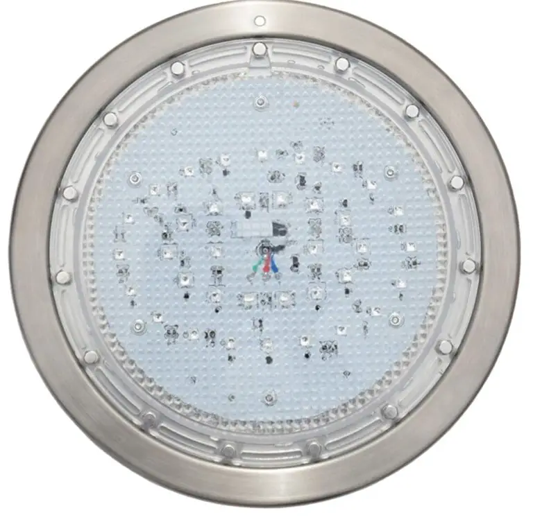
Poolexa 10 Inch Large LED Multicolor Inground Pool Light with 50 Foot Cord for Wet Niche Instruction Manual
WARNING
FOR YOUR SAFETY – This product must be installed and serviced by a contract or who is licensed and qualified in pool equipment by the jurisdiction in which the product will be installed where such state or local requirements exist. The maintainer must be a professional with sufficient experience in pool equipment installation and maintenance so that all of the instructions in this manual can be followed exactly. Before installing this product, read and follow all warning notices and instructions that accompany this product. Failure to follow warning notices and instructions may result in property damage, personal injury, or death. improper installation and/or operation will void the warranty. improper installation and/or operation can create unwanted electrical hazard which can cause serious injury, property damage, or death. ATTENTION INSTALLER – This manual contains important information about the installation, operation and safe use of this product.
This information should be given to the owner/operator of this equipment.
Installing Light Fixture during New Construction
Preparing the light Fixture for installation
NOTE: The lights are available in 12-volt DC version. 12V transformer is built in the control box. No extra transformer is needed. Ensure that the pool meets the requirements of the current National Electrical Code and all local codes and ordinances. A licensed or certified electrician must install the electrical system to meet or exceed those requirements before the underwater light is installed. Some of the requirements of the National Electrical Code, which the pool electrical systems must meet, are as follows:
- The lighting circuit must have a Ground Fault Circuit Interrupter (GFCI) for 120 volt models, and must have an appropriately rated circuit breaker.
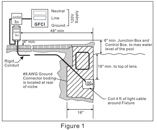
- The junction box (or, for 12 volt models, the low voltage transformer) must be located at least eight (8) inches above water level, at least four (4) inches above ground level, and at least four (4) feet from the edge of the pool. See Figure 1.
- The light fxture and all metal items within fve (5) feet of the pool must be properly electrically bonded to a reliable point of grounding.
- The wet niche must be properly installed so that the top edge of the underwater light’s lens is at least 18 inches below the surface of the water in the pool. See Figure 1.
- The wet niche must be properly electrically bonded and grounded via the No. 8 AWG ground connector located at the rear of the niche. See Figure 1.
Use only approved wet niches (see following note) to ensure a safe and proper installation.
large niche Model numbers:
Jandy Pro Series: PLNICLRG, PLNICVFLRG, SSNICLRG1R, SSNICLRG1S
Pentair: 620004, 78210200 thru 700, 78210401, 79206700
Hayward DuraNiche: SPO600U
Sta-Rite: 05161-2352 thru 2369, 05163-2395 thru 2396 small niche Model numbers:
Jandy Pro Series: PLNICSM, SSNICSM, Pentair: 78241100, 78242200, 78242300 78243100 thru 300, 78244100 thru 300, 79206600
Hayward DuraNiche: SP0601U
Sta-Rite: 05166-1017 thru 1034, 05167-1035 thru 1037
installing the light Fixture
- Feed cord through conduit to junction box, leaving at least four (4) feet of cord at the light fixture to coil into the base of the light niche, see Figure 1. The four (4) feet of cord allows the light to be serviced after the pool is filled with water.
- Cut the cord at the junction box, leaving at least six (6) inches of cord to make connections.
- Strip 2 inches of the outer cord jacket to expose the 4 insulated wires. Be careful not to damage the insulation on the four inner wires.
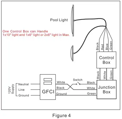
- Install strain relief over cord jacket and connect four wires to the 12V output of the control box .
- Connect control box to 120V supply, Install strain relief over cord jacket and connect 120V input wires of control box to junction box. Black wire is line, white wire is neutral and green is ground.
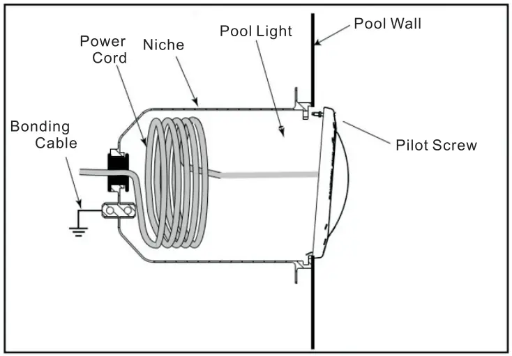
- Engage the retainer tab on the bottom of light back, then pivot the top of the fixture inward and tighten the special pilot screw. See Figure 3.
- Fill the pool until the underwater light is completely submerged in water before operating the light for more than 20 seconds. Turn on main switch or circuit breaker, as well as smartphone, which operates the underwater light, to check for proper operation. Refer to the pool light operating instructions.
WARNING
Never operate this underwater light for more than 20 seconds unless it is totally submerged in water. Without total submersion, the light assembly will get extremely hot, which may result in serious burns or in breakage of LEDs. This may result in serious injury to pool or spa users, installers, or bystanders or damage to property.
Install the Pool Light on a Flat Wall in a Niche less Pool
- Install process is the same as the 1.2 except the mount of light.
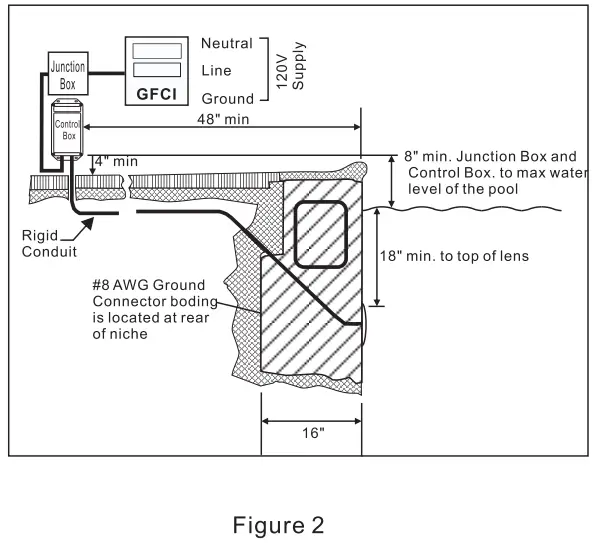
- Drill 1 hole on the flat place you intend to mount the pool light, use 1 expansion screw to fix the light. treat the light with silicon around the light.( you may need to cut off the bolt that is for wet niche install.) See Figure 2.
Replacing New Pool Light Fixture in an Existing Pool or Spa
NOTE: The lights are available in 12-volt DC version. 12V transformer is built in the control box. No extra transformer is needed.
Ensure that the pool meets the requirements of the current National Electrical Code and all local codes and ordinances. A licensed or certified electrician must install the electrical system to meet or exceed those requirements before the underwater light is installed. Some of the requirements of the National Electrical Code, which the pool electrical systems must meet, are as follows:
- The lighting circuit must have a Ground Fault Circuit Interrupter (GFCI) for 120 volt models, and must have an appropriately rated circuit breaker.
- The junction box (or, for 12 volt models, the low voltage transformer) must be located at least eight (8) inches above water level, at least four (4) inches above ground level, and at least four (4) feet from the edge of the pool. See Figure 1.
- The light fixture and all metal items within fve (5) feet of the pool must be properly electrically bonded to a reliable point of grounding.
- The wet niche must be properly installed so that the top edge of the underwater light’s lens is at least 18 inches below the surface of the water in the pool. See Figure 1.
- The wet niche must be properly electrically bonded and grounded via the No. 8 AWG ground connector located at the rear of the niche. See Figure 1.
Replacing the light Fixture
- Turn off the electrical switch or circuit breaker, as well as the switch, which operates the underwater light.
- Unscrew the special pilot screw at top of the face ring and remove the light assembly from the niche, and place the assembly on the deck.
- Remove Junction Box cover, disconnect the light fixture wires and strain relief, and then pull the cord out of the conduit from the niche.
TIP:
lf your old pool light is useless, cut off the old light cord at the light back, connect the old cord with the new light cord. then pull the old cord form the junction box side, the new light cord goes in and the ending comes out of the conduit smoothly. - Feed cord through conduit to junction box, leaving at least four (4) feet of cord at the light fixture to coil into the base of the light niche, see Figure 1. The four (4) feet of cord allows the light to be serviced after the pool is filled with water.
- Cut the cord at the junction box, leaving at least six (6) inches of cord to make connections.
- Strip 2 inches of the outer cord jacket to expose the 4 insulated wires. Be careful not to damage the insulation on the four inner wires.
- Install strain relief over cord jacket and connect four wires to the 12V output of the control box .
- Connect control box to 120V supply, Install strain relief over cord jacket and connect 120V input wires of control box to junction box. Black wire is line, white wire is neutral and green is ground.
- Engage the retainer tab on the bottom of light back, then pivot the top of the fixture inward and tighten the special pilot screw. See Figure 3
- Fill the pool until the underwater light is completely submerged in water before operating the light for more than 20 seconds. Turn on main switch or circuit breaker, as well as smartphone which operates the underwater light, to check for proper operation. Refer to the pool light operating instructions.
WARNING
Never operate this underwater light for more than 20 seconds unless it is totally submerged in water. Without total submersion, the light assembly will get extremely hot, which may result in serious burns or in breakage of LEDs. This may result in serious injury to pool or spa users, installers, or bystanders or damage to property.
Installing the Control Box
Install the outdoor control box on vertical wall, If you can add an overhead awning on the box, it will be more better for protecting the control box.
Wiring the LED Pool Light
Wire the pool light to a standard switch or time switch see Figure 4
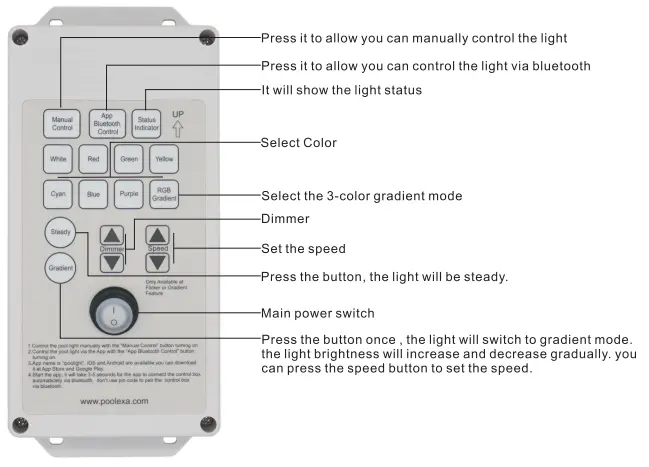
Manual control
You can control the light with the Manual Control button turning on Press the button to control the light. the button functions are shown below.
For Example
- Press on/off switch to turn on the controller
- press the switch “Manual Control”
- press the button “ Blue” once
- the “Status Indicator’ will light in blue and the pool light is also in blue
- if you press the button” Gradient” , pool light brightness will increase to max then decrease to minimum smooth and repeat . you can set the speed and brightness via the button “dimmer” and * speed” .if you press the button * Steady” , pool light will be stable in blue.
- if you press the button “ RGB Gradient” .the light will switch color in red ,green and blue, meanwhile the brightness will increase to max then decrease to minimum and repeat. if you press the button” steady currently, the brightness will be stable but the pool light will switch color in red ,green and blue continually . you can adjust the speed via the button” speed”.
APP Bluetooth Control
It will allow you to control the light via Bluetooth with the Bluetooth control button turning on
Available – on APP Store

Available on Google Play

Search “ipoolight “on APP store / Google Play to download the APP.
Install the APP in your Smart Device,
Ensure Bluetooth is on, press the button “App Bluetooth Control” on the control box, then click the “ipoolight” icon to start the APP. APP will automatically search and match the controller. when you run the APP, it will take 3-5 seconds to build the connection automatically.
NOTE: Don’t use Bluetooth to search and connect the control box with a PIN number. It is a wrong way to connect the control box.
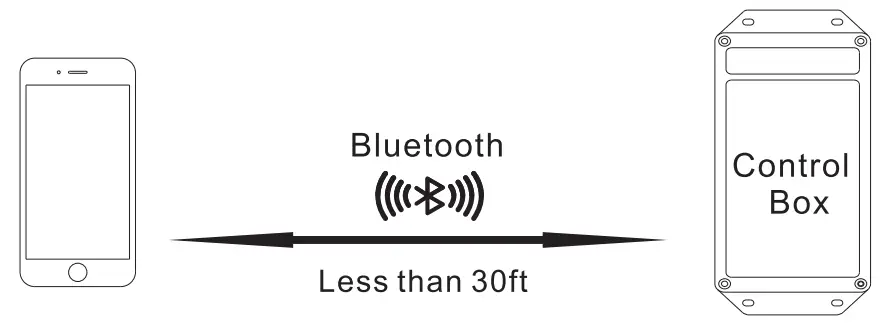
Note: Ensure your smartphone is in 30ft rang form the control box.
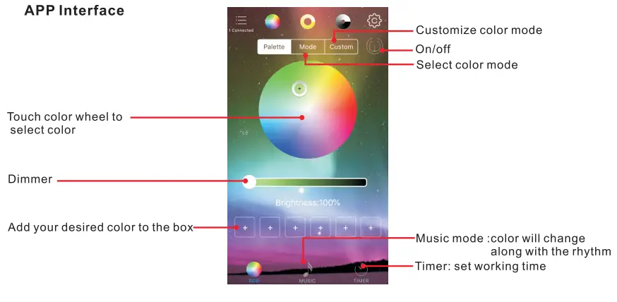
App Interface
NOTE: Manual control setting and Bluetooth control setting are stored in memory separately. manual control and Bluetooth control will not change/overwrite each other.
Troubleshooting
can not build the connection to the controller through Bluetooth
- Ensure 120V power has been sent to the control box, check you junction box and GFCIl.
- Run app to connect controller, it will take 5 -10 seconds to build the connection
- If the connection is successful , you will see the text “ 1 Connected ” on the top left corner of the screen.
- If it still doesn’t work, delete the APP and reinstall it again to have another try.
- You should allow App to access location in your Android device so that you can build the connect through Bluetooth.
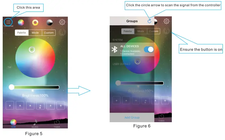
Bluetooth connection is built, but can not to change the color.
Ensure the all device control button is on, try to set it as Figure 5 and 6.
Can’t turn on the pool light manually
- Check the connection between the light and control box.
- Ensure the 120V power supply is sent to the control box, then have a try.
If you can not fix the issue, please leave your message on our website www.poolexa.com , we will help you.
FCC Statement
This equipment has been tested and found to comply with the limits for a Class B digital device, pursuant to part 15 of the FCC Rules. These limits are designed to provide reasonable protection against harmful interference in a residential installation. This equipment generates, uses and can radiate radio frequency energy and, if not installed and used in accordance with the instructions, may cause harmful interference to radio communications. However, there is no guarantee that interference will not occur in a particular installation. If this equipment does cause harmful interference to radio or television reception, which can be determined by turning the equipment off and on, the user is encouraged to try to correct the interference by one or more of the following measures:
- Reorient or relocate the receiving antenna.
- Increase the separation between the equipment and receiver.
- Connect the equipment into an outlet on a circuit different from that to which the receiver is connected.
- Consult the dealer or an experienced radio/TV technician for help.
Caution: Any changes or modifications to this device not explicitly approved by manufacturer could void your authority to operate this equipment.
This device complies with part 15 of the FCC Rules. Operation is subject to the following two conditions:
- This device may not cause harmful interference, and
- this device must accept any interference received, including interference that may cause undesired operation.
RF Exposure Information
The device has been evaluated to meet general RF exposure requirement. The device can be used in portable exposure condition without restriction.