The bike Display
KD986
Product model
Intelligent TFT display for eBike: model: KD986
Specifications
36V148V Power Supply
Rated working current: 50mA
Maximum working current: 200mA
Off leakage current: <1pA
Operating temperature: -20t- 60t
Storage temperature: -30t- 70t
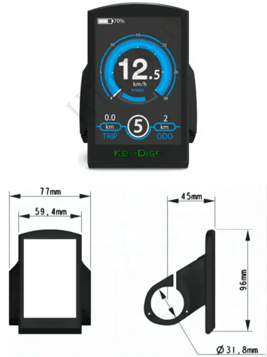
Appearance and Size
KD986 Display appearance and dimension drawing (unit mm)

Remote appearance and dimension drawing (urn mm )
Function Summary
KD0286 can prance a lot of functions to not me users needs. The tree indicating the content is as follows.
- Battery SOC indication (5 bars)
- Motor power indication
- assistance-level indication
- Speed indication Once running speed max speed and avg speed)
- Odometer and trip distance real-assistance function
- Tap time indication
- Backlight about
- Error code indication
- USB connection indicator
- Various parameters settings (e g., wheel size. speed-limited, battery level bar. assistance level, controller limited current. password enable. etc.)
General Operation
Switching the cake System On/Off
To switch on the eBike system. hold the *1 button for 2s.
Hold the 1′ button for 2s again and the eBike system will be switched off and no longer use the battery power
When switching off the cake system, the leakage current is less than 1 pA
When parking the e&Ice for more than 5 minutes. the system switches off automatically.
*Display Interface
After switching on the eBike system, the display will show speed and distance as default.
1. Briefly press the “i” button to switch between following the elements on the lower right.
ODO (Km) 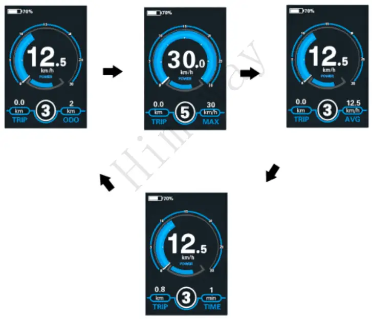 Max. Speed (Km/h)
  Avg. Speed (Km/h)
  Time (Min.)
 Display Indication Cycle Interface
Switching Pedal–Assistance mode °wort
Barely press the button the icon is showing to enter the pedal-assistance level.
To activate the ![]() pedal-assistance function, keep holding the WALK button. After 2s. the ethos drive is activated at a random speed of 6 Km/h. Pedal assistance stops as soon as you release the ‘WALK’ button. The eBike system stops the power output immediately.
pedal-assistance function, keep holding the WALK button. After 2s. the ethos drive is activated at a random speed of 6 Km/h. Pedal assistance stops as soon as you release the ‘WALK’ button. The eBike system stops the power output immediately.

The pedal-assistance function may only be used when pushing the bike. Be aware of the danger of injury when the wheels of the eBike do not have ground contact while using the pedal-assistance function.
Switching the Lighting On/Off
To switch on the headlight, press and hold the ![]() button for 2s. The display backlight brightness is automatically reduced.
button for 2s. The display backlight brightness is automatically reduced.
Press and hold the ![]() button for 2s again and the headlight can be switched oft The display automatically recovers backlight brightness.
button for 2s again and the headlight can be switched oft The display automatically recovers backlight brightness.

*Assist Level Selection
Briefly press the “+” or ” ” button to switch between assist levels in order to change the motor output power. The default assist level ranges from level 0 to level 5. The output power is zero on Level 0. Level 1 is the minimum power and level 5 is the maximum power. When you reach 5, if you press the “+” button again the interface will still show 5 and blinks to indicate the power is at its highest. At level 0, press the “-ft button to reach pedal-assist level. Pressing the – button again still shows and blinks at the pedal-assist level.
Battery SOC Indicator
The Ave green bars represent battery SOC status. The five bars are bright when the battery is at high voltage. Each bar Is equivalent to a capacity of approx. 20%. When the battery is at low voltage, the battery frame will flash to indicate that the battery needs to be recharged immediately.
Battery SOC Indication Interface
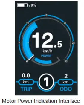
Motor Power Indicator
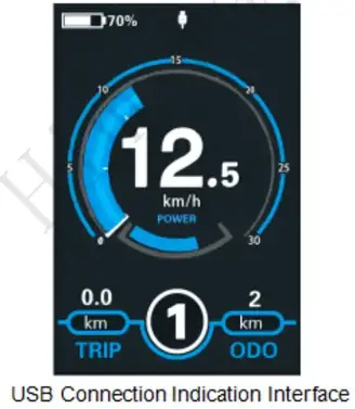
The power of the motor can be read via the interface below:
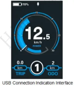
USE connection indication
When a USB external device is inserted into the display, the display interface will show as follows:
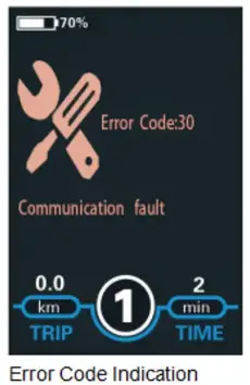
 Error Code Indication
The components of the eBike system are continuously and automatically monitored. When an error Is detected, the respective error code is indicated in the text indication area. Error code Info can be found in Attached list 1.
Have the display repaired when an error code appears
Otherwise, you will not be able to ride the bike normally. Please always refer to an authorized dealer.
Settings
Press the I Minim to turn on the display,
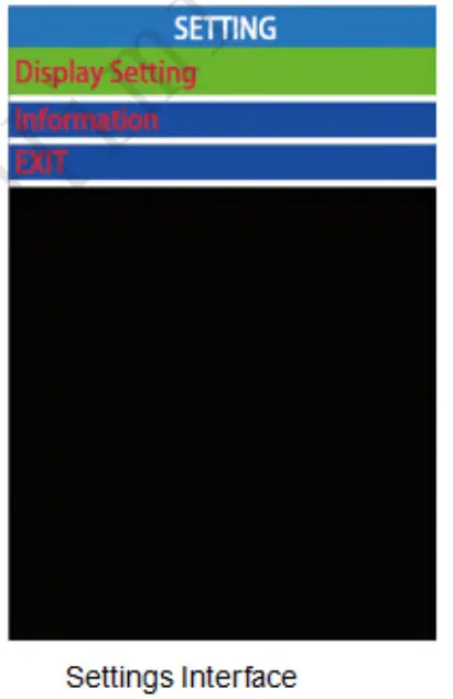
To access the settings menu, hold both the “+” button and the “-” button for 2s.
Display Settings and Information will be listed:
All the settings are operational on a parked bike.
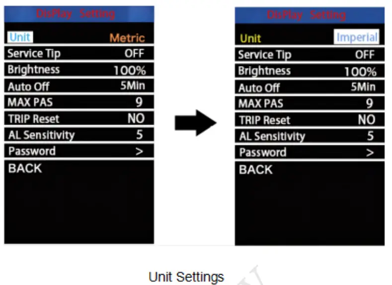
Display Settings
Unit
The unit represents the unit togging settings.
To toggle the unit. Press the “+” button or the ‘-” button to choose the desired unit. then press the “I” button to confirm.
To store a changed setting, press the 1″ button. The default value is metric (Km).
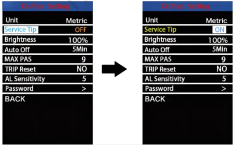
Service Tip
The service tip is the maintenance reminder for eBike users. When the running distance reaches over 5000 km. the word ‘SERVICE-will appears and blinks on the screen.
To change the basic settings. Press the “+” or the button to choose ON or OFF. ON- maintenance reminder Is enabled. OFF- maintenance reminder Is disabled. To store a changed setting, press the 1″ button The default value is ON.
Service Tip Setting Interface
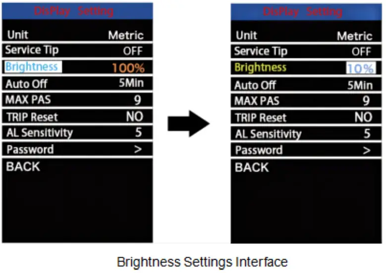
Brightness
Brightness represents LCD backlight brightness settings. The default is 100%. To change the backlight brightness, press the “+” button or the’-‘ button to choose the desired percentage.
To store a changed setting, press the t button.
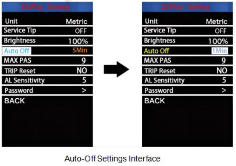
Auto-Oft
Auto-off represents the display of automatic shutdown time settings. To change the display’s automatic shutdown time, press the “+” button or the –button to choose the desired duration The default auto-ott time is 5 minutes. The settable range is 1-9 minutes and OFF. OFF means the auto-ott function is disabled. To store a changed setting. briefly press the 1″ button to confirm.
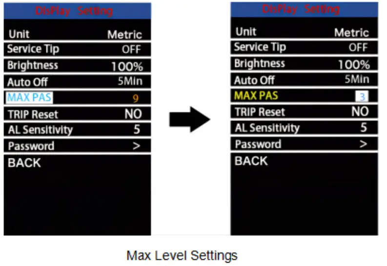
MAX Level
Max level represents the maximum assist level setting. Press the + button or the -‘ button to select the desired value. The settable values are 3/5/9. To store a changed setting, press the 1″ button The default value is
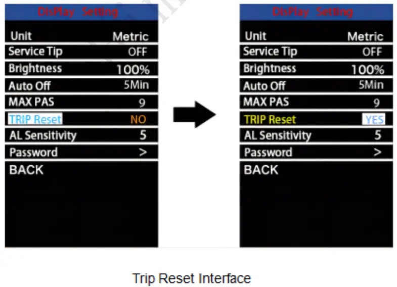
Trip Reset
Trip reset represents the trip distance clearance setting. To reset trip distance. Press the “+” button or the ‘-“ button to select Yes or No. Yes represents clearing a trip distance. No represents not clearing a trip distance To store a changed setting, press the 1 button The default value is NO.
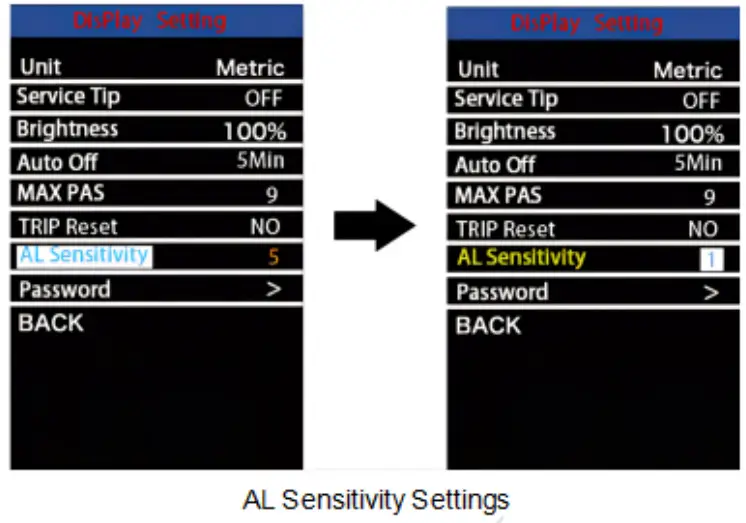
AL Sensitivity
AL sensitivity represents ambient light sensor settings. It can help with automatically adjusting the screen brightness as per the ambient light conditions. When you ride the bike at night or in a place where there is a lack of light. the display backlight and bike light will be turned on automatically. The sensitivity of the AL sensor ranges from 1 to 5 and of (the light sensor function is disabled). The default value is 3. Press the +1- button to choose the desired sensitivity value.
To store a changed setting, briefly press the 1″ button to confirm.
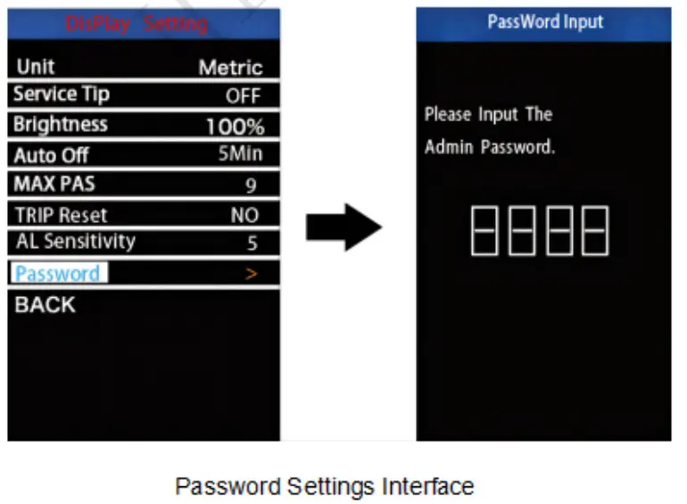
Password
Password is the power-on password settings. On the settings page. select ‘Password’. Briefly press the I button to enter the password setting Interface. Choose -Start Password- and press the I button to confirm. Press +/- to choose ON and press the I button to enable the password function. Press +/- to choose the desired password numbers and press the I button to confirm. When the password is complete, enter the password again and the password setting is done.
• After display settings are done, press BACK to return to the settings interface. information:
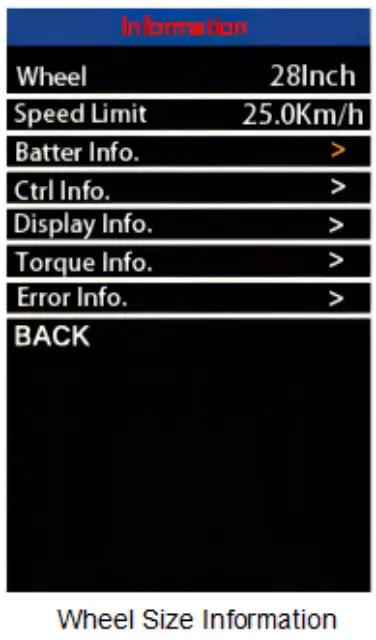
Wheel
The wheel contains the information on the wheel size. It is only for your information and is not settable.
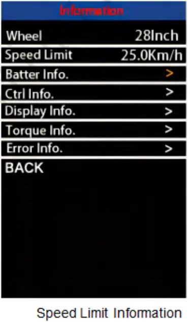
Speed Limit
Speed limit contains the information on the speed limit. It is only for your information and is not settable.
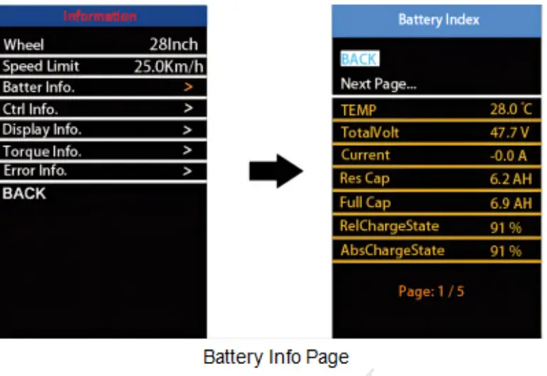
Battery Info
On the information page. choose Battery Info”. Press the I button to check the battery information Choose ‘Back` to exit the battery info page. Choose “Next page” to flick through pages. The viewed Information Includes current temperature, maximum temperature, minimum temperature, total voltage, current, average current, battery SOC, the capacity. relative charging state, absolute charging state. cycle period, maximum non-charging time. recent non-charging time. battery core voltage. etc.
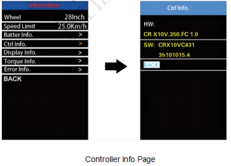
Controller Info
On the information page. choose ‘CM Info’ and press the I button to check the controller software version and hardware version. Press the I button again to exit the controller Information page.
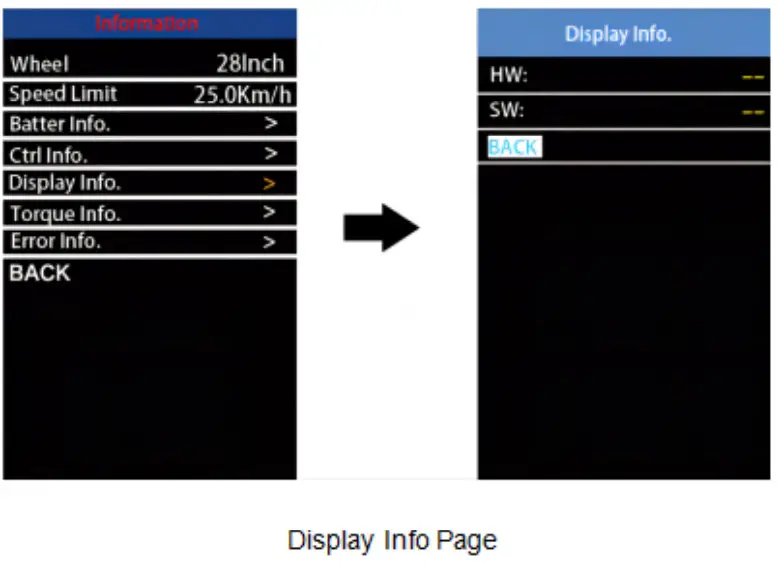
Display Info
On the info page. choose ‘Display Info” and press the I button to check the display software version and hardware version. Press the I button again to exit the display info page.
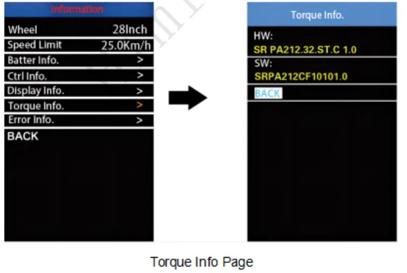
 Torque Info
On the info page, choose “Torque Info” and press the I button to check the torque sensor software version and hardware version. Press the I button again to exit the torque info page.
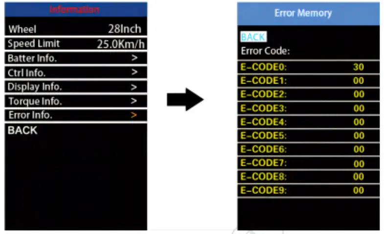
Error Code
On the page, choose Error Code’ and press the I button to check the error code history. You can view up to 10 historical error codes. Press 3 buttons at the same time. ‘WALK’. and ronrOrr. to dear the error codes. Press the I button to exit the error code history page. Please see the code and definition in the Attached list 1.

Warning code info page
If there is any operation within the 20s, the display roils exit We settings state.
Quality Assurance and Warranty Scope
Warranty
- The warranty will be valid only for products used in normal usage and conditions.
- The warranty is valid for 24 months after the shipment or delivery to the customer.
Others
The following items do not belong w our warranty scope
- The display is demolished
- The damage to the display is caused by incorrect installation or
- The shell of the display was broken when the display was out of the factory.
- The wire °Jibe display is broken
- The taut or damage of the display is caused by a force mature (e g., ire. earthquake. etc)
- Beyond the warranty period.
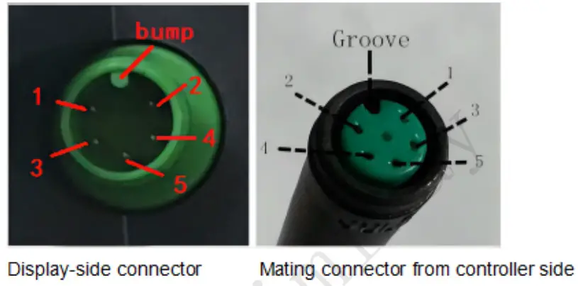
Connection Layout
Connector wire sequence
Wire sequence table
| Wire No | Color | function |
| 1 | Black | |
| 2 | Orange | KEY BUTTON SIGNAL |
| 3 | Green | CAN-H |
| 4 | White | CAN-LOW |
| 5 | Brown | + |
Some wires use a waterproof connector user cannot see the inside color
Operation Cautions
- Be cautious. Do not attempt to disconnect the connector when the battery is on
- Try to avoid hitting the ethke
- Do not modify system parameters to avoid parameter disorder.
- Make sure the display is repaired when an errs code appears
Attached is list 1: Error code definition
| Error code | Definition |
| 04 | Fault with the throttle |
| 05 | The throttle did not return |
| 07 | Overvoltage fault |
| 08 | Fault with motor hall sensor inside |
| 09 | Fault with the motor phase wire |
| 10 | Motor temperature is too high |
| 11 | Fault with a temperature sensor inside motor |
| 12 | Fault with the current sensor inside the controller |
| 13 | Fault with battery temperature inside |
| 14 | The controller temperature is too high |
| 15 | Fault with a temperature sensor inside the controller |
| 21 | Fault with a speed detecting sensor |
| 23 | Fault with the headlight |
| 25 | Fault with torque signal of the torque sensor |
| 26 | Fault with speed signal of the torque sensor |
| 27 | Overcurrent fault |
| 30 | Communication fault |
| 31 | Low voltage protection |
| 32 | High voltage protection |
| 33 | Fault with a brake detecting sensor |
| 35 | Fault with 15V power detecting sensor |
| 36 | Fault with a key detecting sensor |
| 37 | Fault with watchdog |
| 61 | Shifter is stuck |
| 62 | Shifter not reset |
| 81 | Fault with Bluetooth |
| 41 | The total voltage is too high |
| 42 | The total voltage is too low |
| 43 | The total current is over the limit |
| 44 | Monomer voltage is too high |
| 45 | The battery temperature is too high |
| 46 | The battery temperature is too low |
| 47 | SOC is too high |
| 48 | SOC is too low |
| 71 | Fault with the electronic lock |