ENSTO ECO10F Floor Thermostat Instruction Manual
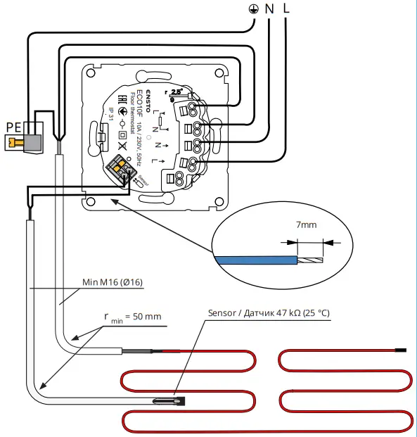
Connection diagram
| Table 1 | |
| T / ºC | R / kΩ |
| 5 | 121 |
| 10 | 94 |
| 20 | 59 |
| 30 | 38 |
| 40 | 25 |
| 50 | 17 |
| 60 | 11 |
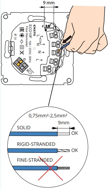
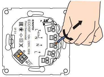
Connection of wires to the thermostat
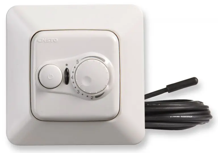
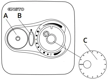
User interface
Installation and uninstallation
Introduction
ECO10F and ECOINTRO10F floor thermostats are for room-specific control of electric floor heating.
Safety instructions
 Electrically skilled person
- The installation must only be done by an electrician with the appropriate qualifications.
- Read this manual carefully before starting the installation work.
- Follow the instructions in this manual, and make sure that the installation complies with national safety regulations, installation methods and restrictions.
- The information provided in this manual in no way exempts the installer or user from responsibility to follow all applicable safety regulations.
- This manual is a part of the product and must be stored in a safe location so that it is available for future installation and service.
WARNING
 Danger of electric shock! Risk of fire!
- Disconnect the power supply before carrying out any installation or maintenance work on this thermostat and associated components.
- Do not switch on the power supply before the installation work is completed.
- Improper installation can cause personal injury and property damage.
- Do not operate a defect thermostat.
Before installation
- Make sure that all the parts and tools needed for the installation are available.
- Make sure that heating load is equivalent to the thermostat power endurance.
- Measure the insulation resistance and circuit resistance of the heating load controlled by the thermostat.
Installation, figures 1, 2 and 4
- Mount the thermostat as the cover of a 1-component mounting box or as a part of a multiple component instrument panel.
- Place the sensor cable in a dry protective tube between heating cables.
NOTE! Make sure that there is not water in the protective tube. - Connect the earthing wires (PE) to the separate connector.
- Connect the thermostat to the mains and load according to figures 1 and 2.
• Connect the supply conductors. The stripping length is 9 mm.
• Connect the sensor cable to the sensor marked connector. The stripping length is 7 mm.
• The thermostat has spring connectors. Disconnected the conductors from the spring connectors by twisting and pulling at the same time.
• Use a residual circuit breaker according to local installation regulations. - Install the thermostat into the mounting box with screws.
- Install the thermostat lid, cover plate and adjustment knob. Cover the thermostat from potential dust during construction work.
Commissioning and operation, figure 3
- Switch on the heating from the switch A. The signal light B is green when the thermostat is functioning and the light turns red when the load is connected.
- Set the desired floor temperature with the adjustment knob C.
- When the thermostat is functioning normally, you can hear a faint click when the load is switched on and off.
Technical data
| Supply voltage | 230 V -15%, +10%, 50 Hz |
| Switch contact | 2-pole |
| Rated current | 10 A |
| Maximum load | 2300 W |
| Thermostat adjustment range | 10 … 60 °C |
| Operating temperature range | -20 … +30 °C |
|
Signal light B |
green: thermostat on, heating off |
| red: heating on | |
| Floor sensor | NTC, 47 kΩ at 25°C, cable 4 m (extendable to 10 m) |
| Floor sensor resistance values | see page 2, table 1 (the sensor is not connected) |
| Circuit breaker/fuse | max. 16A |
| Power in standby | < 0,5 W |
| Ingress Protection | IP31 |
Thermostat can control an external relay.
Warranty
The warranty period for Ensto ECO thermostats is 2 years from the date of purchase but no longer than 3 years from the date of manufacture. Warranty conditions, see the product card www.ensto.com.
Disposal
 Do not dispose of electrical and electronic devices including their accessories with the household waste.
- The product’s cardboard packing is suitable for recycling.
- When a heating system is at the end of the life cycle the cables, conduits and electronic components must be disposed of properly according to local recycling guidelines.