WiFi 2.4G RJ45 D WiFi Adapter
Product Information
The WiFi 2.4G RJ45 D adapter is a device that can transmit
operational data from solar controllers, inverters, or
inverter/chargers to a cloud server in real-time through a local
2.4G WiFi network. It supports local monitoring and cloud working
modes and can be used immediately after connecting with easy and
convenient operation. The adapter is suitable for devices with RJ45
ports and is directly powered by the communication port. It has a
communication distance of up to 20 meters and can work in a
temperature range of -40~85 degrees Celsius.
Features
- Suitable for controllers, inverters, or inverter-chargers with
RJ45 port - Can be used immediately after connecting, with easy and
convenient operation - Directly powered by the communication port
- Up to 20 meters of communication distance
- Supports Local monitoring and Cloud working modes
Specifications
| Model | WiFi 2.4G RJ45 D |
| Working voltage | 4.5V~5.5V |
| Power consumption | Peak consumption of 150mA |
| Enclosure | N/A |
| Communication method | 2.4G WiFi network |
| Communication parameters | 115200Bps, 8N1 Communication standard V1-1.0 |
| Interface standard | RJ45 |
| Work frequency | 2.4 ~ 2.4835 GHz |
| Work temperature range | -40~85 degrees Celsius |
| Dimension | 63mm x 19mm x 10mm |
| Net weight | 7.7g |
Product Usage Instructions
Installation
Do not install the WiFi adapter in humid, salt spray, corrosion,
greasy, flammable, explosive, dust accumulative, or other severe
environments. Connect the RJ45 connector of the adapter to the RJ45
port of the controller, inverter, or inverter/charger.
Working Processes
Scenario 1: There is a local 2.4G WiFi network
- Turn on the WiFi switch on the mobile phone and connect to the
local WiFi network (a 2.4G WiFi network is a must). - Log into the app and click the icon to add a new gateway.
- Select the gateway model.
- Input the gateway data (Gateway SN is the 22-digit number of
the gateway WiFi name), and click Next Step to enter the device
adding page. - After adding the device, click Next Step to enter the above
page. - Input the local WiFi password and click Next Step.
- Click Go to set up Wi-Fi to connect phone to the gateway WiFi
(HN_EPSN: xxxxxx,password:12345678). - Return to the app after connection and click Next Step.
- After the gateway is successfully connected, connect the phone
to local WiFi or 4G with Internet access. Then you can monitor the
device through the app.
Scenario 2: There is no local 2.4G WiFi network
- Login to the app and click My>Collect Data.
- Select all products and click Synchronize data to download
data.
WARNING: The WiFi adapter is not compatible
with the PU1024B/PU2024B, PU1024BW/PU2024BW, and LS-B series
controllers. If the WiFi adapter is installed in a metal cabinet,
the signal strength and distance will be reduced, depending on the
material and size of the cabinet.
View Fullscreen
Thank you for selecting this WiFi 2.4G RJ45 D adapter; please read this manual carefully before using the product.
Do not install the product in humid, salt spray, corrosion, greasy, flammable, explosive, dust accumulative, or other severe environments.
1. Overview
WiFi Adapter
WiFi 2.4G RJ45 D
Through a local 2.4G WiFi network, the WiFi 2.4G RJ45 D can transmit all operational data from the solar controller, inverter, or inverter/charger to the cloud server in real-time. Users can remotely monitor connected devices and program parameters via the server platform and mobile app.
Features
Suitable for controllers, inverters, or inverter-chargers with RJ45 port Can be used immediately after connecting, with easy and convenient operation Directly powered by the communication port Up to 20 meters of communication distance Supports the “Local” monitoring and “Cloud” working modes.
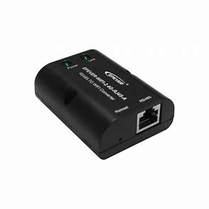
2. Appearance
3. Specifications
Pin Definition Pin Definition
1
+5VDC
5
RS485-A
2
+5VDC
6
RS485-A
3
RS485-B
7
GND
4
RS485-B
8
GND
Parameter
Model
WiFi 2.4G RJ45 D
Working voltage Power consumption
Enclosure Communication method
5V± 0.5V(Powered by RS485 com. port) Peak: 150mA; Idle: 310uA IP30 RS485
Communication parameters Interface standard Work frequency
Work temperature range
115200Bps, 8N1 Communication standard V1-1.0
2.4 ~ 2.4835 GHz -40~ 85
Dimension Net weight
63mm x 19mm x 10mm 7.7g
Note: The WiFi adapter working voltage is 4.5V~5.5V and peak consumption is 150mA, so it is only suitable for devices that meet this requirement.
4. Working processes
RJ45 connector: Connect to the RJ45 port of the controller, inverter, or inverter/charger. RJ45 Pin Definition
1
Connect the WiFi adapter to the RJ45 port of the device. Add the WiFi adapter into the cloud by the PC or mobile app. WARNING: The WiFi adapter is not compatible with the PU1024B/PU2024B, PU1024BW/PU2024BW and LS-B series controllers. If the WiFi adapter is installed in a metal cabinet, the signal strength and distance will be reduced, depending on the material and size of the cabinet.
2
Scenario 1: There is a local 2.4G WiFi network. The WiFi adapter can upload the collected data to the cloud automatically.
Step1: Turn on the WiFi switch on the mobile phone, and connect to the local WiFi network (a 2.4G WiFi network is a must).
Step2: Log into the app
and click the icon to add a new gateway.
Step3: Select the gateway model.
Step4: Input the gateway data (“Gateway SN” is the 22-digit number of the gateway WiFi name), and click “Next Step” to enter the device adding page.
Step5: After adding the device, click “Next Step” to enter the above page.
Step6: Input the local WiFi password and click “Next Step.”
Step7: Click “Go to set up Wi-Fi” to connect phone to the gateway WiFi
(HN_EPSN: xxxxxx,password:12345678). Return to the app after connection, and click “Next Step.”
Step8: After the gateway is successfully connected, connect the phone to local WiFi or 4G with Internet access. Then you can monitor the device through the app.
Scenario 2: There is no local 2.4G WiFi network.The WiFi adapter cannot upload the collected data to the cloud.
Step1: Login to the app and click “My>Collect Data.” Select all products and click “Synchronize data” to download data.
Step2: After all data is downloaded, return to the app. Click “Home > Offline.”
Step3: Select the module type (WIFI)
Step4: Turn on the
phone WiFi switch and
connect the phone to the
gateway
WiFi(HN_EPSN:
xxxxxx,
password:
12345678).
Step5: Return to the app and
click
“Equipment>Add
equipment” (“GatewaySN” is
the 22-digit number of the
gateway WiFi name).Click
“Confirm” to add the device.
Step6: On the “Device
List” page, click the
gateway SN to enter the
device’s
real-time
monitoring page.
Please note that changes can be made without prior notice. Version number: V1.1