IOTAVX SA 3 Integrated Amplifier
PLEASE READ THESE IMPORTANT SAFETY INSTRUCTIONS AND KEEP IN A SAFE PLACE
- Read these instructions.
- Keep these instructions.
- Heed all warnings.
- Follow all instructions.
- Do not use this apparatus near water.
- Clean only with a dry cloth.
- Do not block any ventilation openings. Install in accordance with the manufacturer’s instructions.
- Do not install near any heat sources such as radiators, heaters, stoves, or another apparatus (including amplifiers) that produces heat.
- Do not override the safety features of the polarized or grounding-type plug. A polarized plug has two blades with one wider than the other. A grounding-type plug has two blades and a third grounding prong. The wide blade or the third prong, are provided for your safety. If the provided plug does not fit into your outlet, consult an electrician for replacement of the obsolete outlet.
- Protect the power cord from being walked on or pinched particularly at plug points, sockets and at the point that they exit from the unit.
- Only use attachments/accessories specified by the manufacturer.
- Use only with the cart, stand, tripod, bracket, or table specified by the manufacturer or sold with the apparatus. When a cart is used, use caution when moving the cart/apparatus combination to avoid injury from tip-over.
- Unplug this apparatus during lightning storms or when unused for long periods of time.
- Refer all servicing to qualified service personnel. Servicing is required when the apparatus has been damaged in any way, such as when a power-supply cord or plug is damaged, liquid has been spilled or objects have fallen into the apparatus, the apparatus has been exposed to rain or moisture, does not operate normally, or has been dropped.
- Refer to the manufacturer’s operating instructions for power requirements. Be advised that different operating voltages may require the use of different line cords and/or attachment plugs.
- Do not install the unit in an unventilated rack.
- Never attach audio power amplifier outputs directly to any of the unit’s connectors.
- The user should not attempt to service the appliance beyond that described in the operating instructions. All other servicing should be referred to qualified service personnel
This equipment has been tested and found to comply with the limits for a Class B digital device, pursuant to Part 15 of FCC Rules. These limits are designed to provide reasonable protection against harmful interference in a residential installation. This equipment generates, uses and
radiates radio frequency energy and, if not installed and used in accordance with the instructions, may cause harmful interference to radio or television reception.
This can be determined by turning the equipment off and on. The user is encouraged to try to correct the interference by one or more of the following measures:
- Re-orient or relocate the receiving antenna.
- Increase the separation between the equipment and the receiver.
- Connect the equipment to an outlet on a circuit different to the one that the receiver is connected to.
- Consult the dealer or an experienced radio/television technician for help.
Product Description
Front Panel
- 1. Standby Indicator Light
When the power amplifier is in standby, the light will glow red. When the power amplifier is in operating mode it will glow white. When the power amplifier has detected a problem (protection due to short on output for example) the light will blink red. - Volume Control
Controls the volume level of all audio channels, as well as access to the various menu functions and adjustment. - Headphone Jack
Output audio signals for the use of listening with headphones. - VFD Display
A vacuum fluorescent display (VFD) is used to display all menu details and functions.
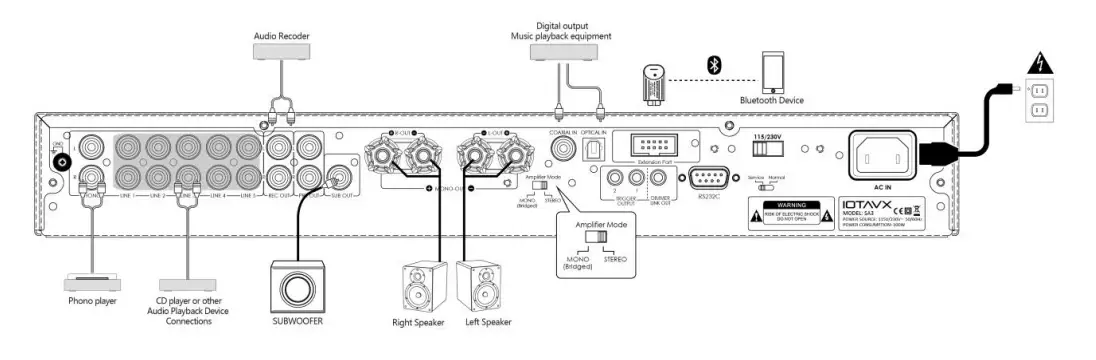
Rear Panel
- Analog Inputs
You have the option of using multiple analogue inputs namely PHONO (MM), LINE1, LINE2, LINE3, LINE4, LINE5. - REC OUT
This analog audio output is for connecting a recorder with an analog audio input. - PRE-OUT
If you want to connect to the IOTAVX PA3 power amplifier and use SA3 as a preamplifier, connect it to the PRE-OUT jacks. - SUB-OUT
- Speaker Terminals
These are terminal posts for connecting L/R speakers. - Coaxial In / Optical In
These coaxial/optical digital audio inputs are for connecting components with coaxial/optical digital audio outputs, such as CD and BD /DVD players. - Expansion Port
To connect the Bluetooth module socket or another extension module to be added to the range at a later stage. - Power switch for 115V/230V
This switch is used to select between 115V or 230V. - AC Input
Socket for connecting the supplied IEC Mains Power Cord for connection to mains power - Firmware Update Operation Switch
For normal operation, leave this switch at the “Normal” position. If updating the unit, set this switch to the “Update” position. - RS232C
RS232C port for firmware upgrade or external control via a control system. - Dimmer Link Out
The DIMMER LINK OUT jacks are used to control the brightness and the brightness of other connected IOTAVX products. - Trigger Output
Connects to the trigger input and output jacks on other connected components to control the power amplifier. This enables the amplifier to turn on or go into standby state based on the standby status of the connected component. - Amplifier Mode
When the amplifier mode has been selected, this switches the SA3 between stereo mode and MONO (Bridged). Refer to later sections of this manual for more information
Remote Control
- ON /Standby mode
Press this button to switch the unit between ON / STANDBY mode. 2. 2, 3, 4, 5,15,16 analogue inputs Press to select PHONO, LINE1, LINE2, LINE3, LINE4, LINE5. - button
- Extension Port
When you press extension port, change to Bluetooth source. - Audio button
Press audio button to select bass, treble, balance. - VOL /AUDIO + – button
Press [VOL /AUDIO + -] to adjust the VOLUME up or down in any mode. 10. DIM button
To adjust the luminance of the unit. - Button
to select the Next track in Bluetooth mode. - Button
to start or pause playback in Bluetooth mode. - Optical
Press Optical to select Digital optical input source. - Coaxial
Press Coaxial to select Digital Coaxial input source. - Mute
Press mute button to mute the unit.
Connections
Before making any connections, read the manuals supplied with your other components. Do not connect the power cord until you’ve completed and double-checked all connections.
Connection Color Coding:
RCA-type Audio connections are usually color-coded: Red and White. Use Red plugs to connect right-channel audio inputs and outputs (typically labeled “R”). Use White plugs to connect left-channel audio inputs and outputs (typically labeled “L”).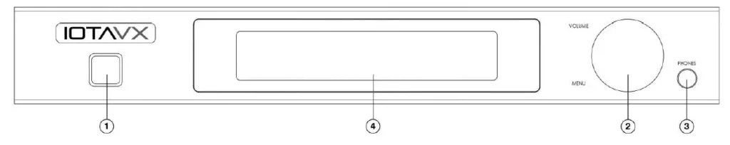
- Push plugs in all the way to make good connections (loose connections can cause noise or malfunctions).
- To prevent interference, keep audio and video cables away from power cords and speaker cables.
Cables and Jacks 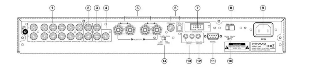
Speaker Connections
- Disconnect the power cord from the wall outlet before making or changing any connections.
- Check the impedance of your speakers. Only connect speakers with an impedance of 4 ohms or more.
- The amplifier’s red speaker terminals are the + (positive) terminals and the black terminals are the – (negative) terminals. The + side of the speaker cable is marked to make it distinguishable from the – side of the cable. Connect this marked side to the red + terminals and the unmarked side is the black terminal.
- Prepare the speaker cables for connection by stripping off approximately 10 mm or less of the outer insulation (no more as this could cause a short circuit). Twist the wires tightly so that they do not have any frayed or loose ends.
Making the Speaker Cable Connections: 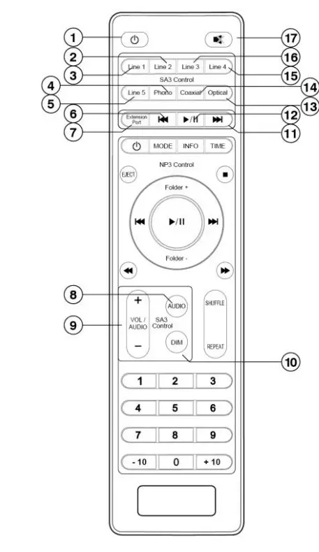
- Unscrew the Knob
- Insert the bare speaker cable end through the hole in the post
- Tighten down the knob (finger tight only) to secure the cable
Stereo Connection
This is an example of a stereo connection using the CD player or other device.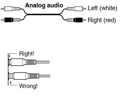
Please Note!!
Set the Amplifier Mode switch to Stereo Mode
Mono (Bridge) Connection
This is an example of the Mono (Bridge) connection with the CD player, SA3, PA3. Please note that when used as a mono power amp, the SA3 will always amplify the right input signal and output to the connected speaker. Please connect the PA3 to the left preamp output “PRE-OUT” of the SA3.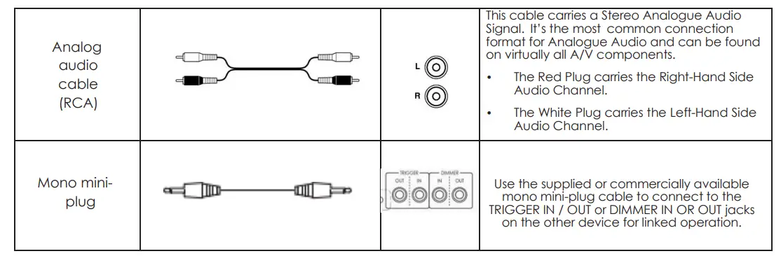
Please Note!!
Set the amplifier Mode switch to Mono (Bridge) position.
Basic Operation
Turning on the unit: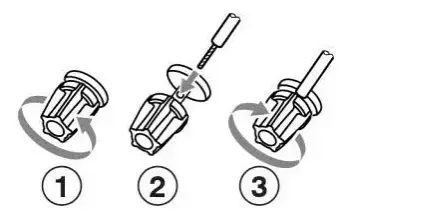
- Press ON/STANDBY to turn on the amplifier. The power amplifier comes on, and the Power LED will illuminate white.
- Press the ON/STANDBY button again to set the amplifier to Standby. The power amplifier will enter Standby mode, and the Power LED will illuminate red.
Analogue Audio Output Jacks:
This unit has one pair of Analogue Audio Output Jacks. This output can be used to send a signal of what is currently being listened to, to an analogue recording device such as a Tape Recorder.
- Connect to Recording equipment using Analogue RCA cables (Stereo 2RCA-2RCA):
Subwoofer Pre-Out:
This unit has a single Mono Subwoofer Pre-Out Jack, SUB OUT for connection to an Active (Powered) Subwoofer. This jack will output a low frequency signal and its level is automatically raised and lowered along with the main Volume control.
- Connect to an Active (Powered) Subwoofer using Analogue RCA cable (Mono 1RCA-1RCA):
Troubleshooting
To determine any problem with your integrated power amplifier, always check the most obvious possible causes first. If any problems remain after you have checked the items below, please consult your nearest Authorized Dealer or Authorized IOTAVX Service Center. If you experience any of the following difficulties while using the system, use this troubleshooting guide to help remedy the problem before requesting servicing. Should any problems persist, consult your nearest authorized dealer or authorized Service Agent. If the unit does not operate normally due to external influence such as static electricity, disconnect the power plug from the wall outlet and insert again to return to normal operating conditions.
| PROBLEM | POSSIBLE CAUSE | REMEDY |
| Main Amplifier: | ||
| When listening to the music in stereo.
Left/right speakers reversed. |
Speakers are connected incorrectly. | Check, and reconnect as required. |
| Sound is only heard from one
channel. |
One of the input cords is disconnected. | Connect the input leads. |
| Sound cuts off when listening or no sound even though power is ON. | Speaker impedance is lower than recommended for this unit, therefore overloading the Amplifier. | After turning off the power and then turning it on again, reduce the volume or change to the
correct 4/8-ohm speakers. |
| Low bass response. | Speaker polarity (+/-) is reversed. | Check all speakers and speaker wires for correct polarity. |
Specification
| ITEM | SPECIFICATIONS | |
| Amplifier: | ||
| Continuous Power Output (Stereo) | 50 Watts x 2CH (20Hz – 20kHz, <0.07%, 8Ω) | |
| 100 Watts x 2CH (20Hz – 20kHz, <0.07%, 4Ω) | ||
| Continuous Power Output(Mono/
Bridged) |
100 Watts x 1CH (20Hz – 20kHz, <0.07%, 8Ω) | |
| 180 Watts x 1CH (20Hz – 20kHz, <0.07%, 4Ω) | ||
| Total Harmonic Distortion | < 0.02% @ 1kHz | |
| Frequency Response | 20Hz – 100kHz | |
| Input Sensitivity – Line Inputs | 200mV | |
| Input Sensitivity – Phono Input | 2.5mV | |
| Input Overload – Line Inputs | 4V | |
| Signal to Noise Ratio (IHF “A” | > 100dB | |
| Channel Separation – Line Inputs | > 80dB | |
| General: | ||
| Standby Power Consumption | < 0.5W | |
| Power Requirements – AC | AC230V / 50Hz, AC115V / 60Hz SELECTABLE | |
| Power Consumption | 220W Maximum | |
| Dimensions – Main Unit | 432mm x 240mm x 59mm (W x D x H) | |
| Weight – Main Unit | 6.5Kg | |