![]() LMRC-211 Wattstopper DLM Single Relay
LMRC-211 Wattstopper DLM Single Relay
w-0-10V Dimming Room Controller
User Guide
Catalog Numbers
LMRC-211/LMRC-211-347
Country of Origin: Made in China
LMRC-211-U and LMRC-211-347 -U are BAA and TAA compliant (Product produced in the U.S.)
This unit is pre-set for Plug n’ Go™ operation, adjustment is optional.
For full operational details, adjustments,s and more features of the product see the DLM System Installation Guide provided with Wattstopper room controllers, and also available at www.legrand.us/Wattstopper.
Installation shall be in accordance with all applicable regulations, local and NEC codes. Wire connections shall be rated suitable for the wire size (lead and building wiring) employed.
For Class 2 DLM devices and device wiring: To be connected to a Class 2 power source only. Do not reclassify and install as Class 1, or Power and Lighting Wiring.
IMPORTANT SAFEGUARDS
When using electrical equipment, basic safety precautions should always be followed including the following:
a. READ AND FOLLOW ALL SAFETY INSTRUCTIONS.
b. Do not use outdoors.
c. Do not mount near gas or electric heaters.
d. Equipment should be mounted in locations and at heights where it will not readily be subjected to tampering by unauthorized personnel.
e. The use of accessory equipment not recommended by the manufacturer may cause an unsafe condition.
f. Do not use this equipment for other than intended use.
g. Installation should be performed by qualified service personnel.
SAVE THESE INSTRUCTIONS
SPECIFICATIONS
Voltage
LMRC-211 Input Voltage … Single Phase 120/230/240/277VAC, 50/60Hz
LMRC-211-347 Input Voltage …………………………… 347VAC, 50/60Hz
Load Requirements
LMRC-211 relay rated for up to:
Incandescent. …………………………………………………20A @ 120VAC
Ballast …………………………………………………….20A @ 120/277VAC
E-Ballast ……………………………………………………16A@120/277VAC
Motor …………………………………………………………… 1Hp @ 120VAC
LMRC-211-347 relay rated for up to:
Ballast/LED Driver …………………………………………..15A @ 347VAC
Class 2 Dimming Output, 0-10V ………………….sinks up to 100mA per channel
Output to DLM Local Network …………………………. up to 250mA @ 24VDC
Connection to the DLM Local Network ……………………………. 4 RJ-45 ports
DLM Local Network characteristics when using LMRC-11x/2xx room controllers:
Low voltage power provided over Cat 5e cable (LMRJ); max current 800mA. Supports up to 64 load addresses, 48 communicating devices including up to 4 LMRC-10x series and/or LMPL-101 controllers, and LMPB-100.
Free topology up to 1,000’ max.
Environment ……………………………………………………… For Indoor Use Only
Operating Temperature ………………………….32° to 158°F (0° to 70°C)
Storage Temperature ……………………………23° to 176°F (-5° to 80°C)
Relative Humidity ……………………………….5 to 95% (non condensing)
Patent Pending
UL2043 Plenum Approved – Suitable for Use in Air Handling Spaces UL/CUL Listed under UL60730:
Type 1
Operating Control – For Electronic Ballast, CFLs, LED, LED Lamps, Motors and Incandescent Lamps.
Independently Mounted for Surface Mounting
Pollution Degree 2
Software Class A
Impulse Voltage Rated – 4000V
The LMRC-211 is also Complementary Listed to “Emergency
Lighting Equipment”, (UL924) intended for Indoor Dry Locations
(does not apply to LMRC-211-347).
CAUTION: TO CONNECT A COMPUTER TO THE DLM LOCAL NETWORK USE THE LMCI-100. NEVER CONNECT THE DLM LOCAL NETWORK TO AN ETHERNET PORT – IT MAY DAMAGE COMPUTERS AND OTHER CONNECTED EQUIPMENT.
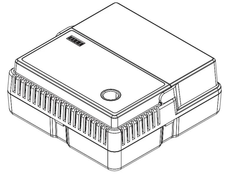
MOUNTING THE CONTROLLER
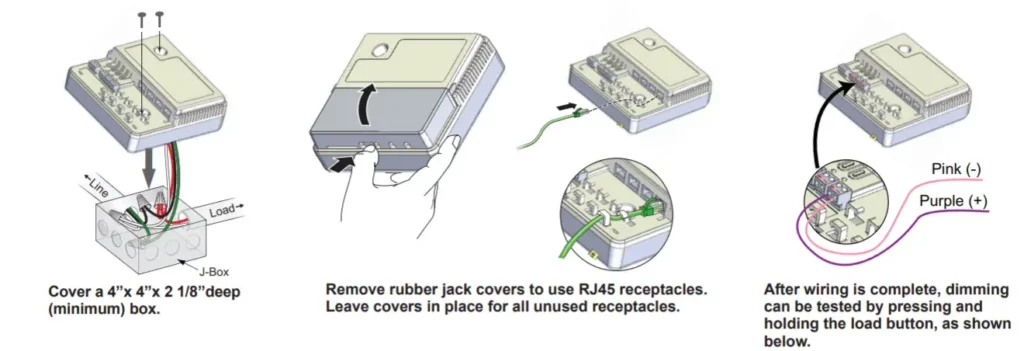
The room controller mounts as the cover for a four-square deep junction box. After connecting the load and line wires, secure the LMRC-211 to the cover tabs on a deep junction box using two screws.
CAUTION: Mount the device in an upright vertical or horizontal position with side ventilation openings located above the bottom/base surface.
![]() WARNING: TURN THE POWER OFF AT THE CIRCUIT BREAKER BEFORE WIRING.
WARNING: TURN THE POWER OFF AT THE CIRCUIT BREAKER BEFORE WIRING.![]()
Attaching LMRJ Cables
0-10V Connections
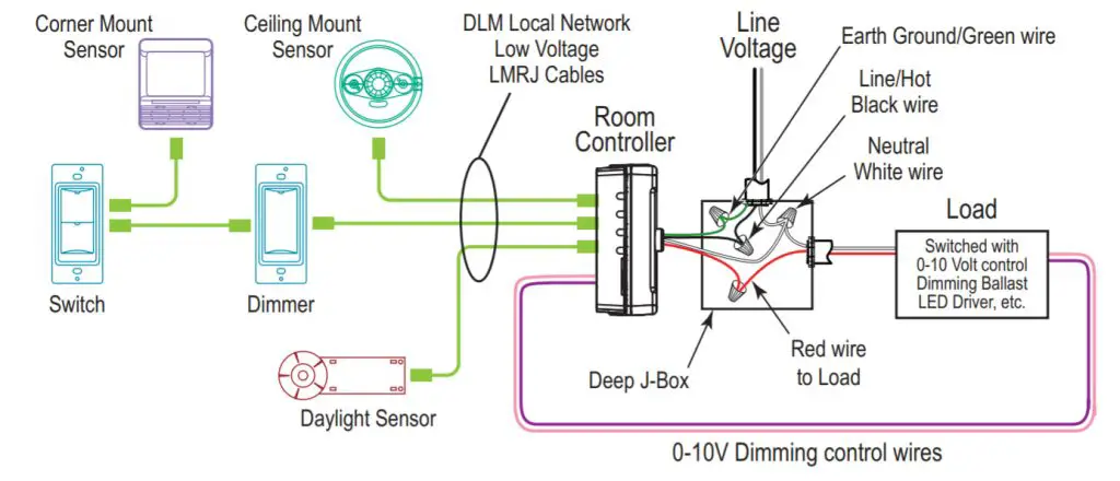
PLACEMENT EXAMPLE
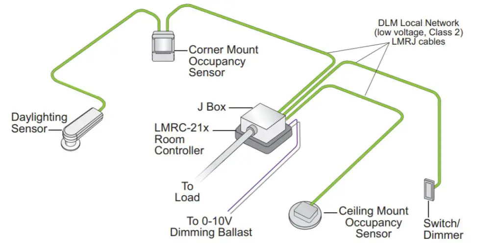
CONNECTIVITY
Both Room Controllers communicate to all other DLM devices connected to the DLM Local Network. Connections shown are for example only. The low voltage LMRJ cables can connect to any DLM device with an open RJ45 receptacle.
All line voltage wiring is #12 AWG. The LMRC-211 is rated for up to 20A. The LMRC-211-347 is rated for up to 15A. Do not connect different load types to the relay. For dimming ballasts or drivers, connect the 0-10V control wires to the 0-10V terminals that match the load relay output connection.
USING THE LMRC-211 WITH EMERGENCY LIGHTING
NOTE: If any Emergency Circuits are fed or controlled from a panel, they must be located electrically where fed from a UPS, generator, or other guaranteed source of power during emergency and power outage situations.
When used with an ELCU
Wattstopper recommends using an ELCU device when the Emergency Light should turn On and Off based on a Normal Power Circuit in the room. In this scenario, the LMRC-211’s 0-10VDC dimming circuit is connected to and alters the light level of both normally powered lighting loads and emergency powered lighting loads. The 0-10V signal is generated individually by each ballast or driver when they are powered. 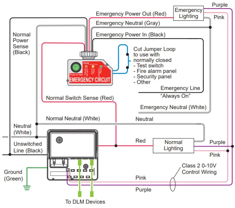
When Normal Power is available:
When Normal Power is available and the normal load has been turned off by any DLM device (OS, photocell, or dimmer switch, or LMRC override button), the ELCU will turn off the Emergency Load as well.
When Normal Power is unavailable:
When normal power to the room controller fails for any reason, the 0-10VDC dimming circuit in the LMRC-211 will revert to an open circuit. Since no device is controlling the 0-10V circuit, any fixture that is fed by emergency power will go full-on. Fixtures fed by normal power will be off since there is no power available for their operation.
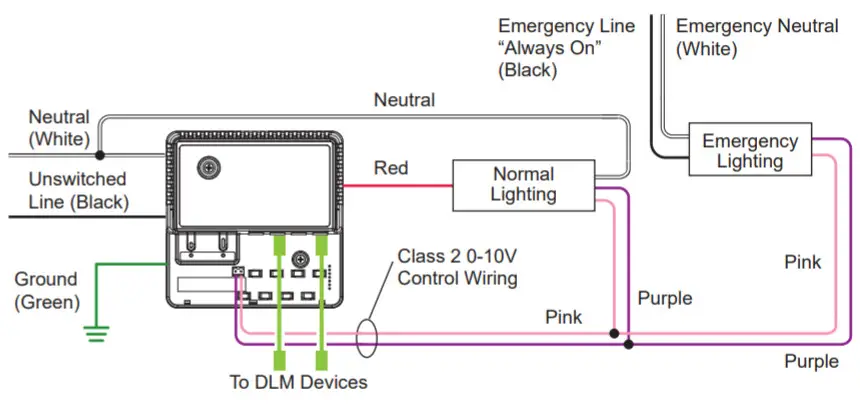
When no ELCU is used:
In this scenario, emergency lighting cannot be turned off by a DLM device, only dimmed to its lowest possible level. The normal lighting load has full control. As in the example with the ELCU, if normal power fails, the emergency load will go full-on. If any Emergency Circuits are fed or controlled from a panel, they must be located electrically where fed from a UPS, generator, or other guaranteed source of power during emergency and power outage situations.
PLUG N’ GO OPERATION (PNG)
Plug n’ Go supports the most energy-efficient control strategy. For example, if one load, one switch, and one occupancy sensor are connected to the DLM local network, the system operates the load as Manual-On, Automatic-Off.
See DLM device Quick Start Guides to determine how each device affects the PNG operation of the LMRC-211 and the LMRC-211-347.
Load Control Arbitration
To take full advantage of automatic PnG configuration, review these simple rules about load control arbitration.
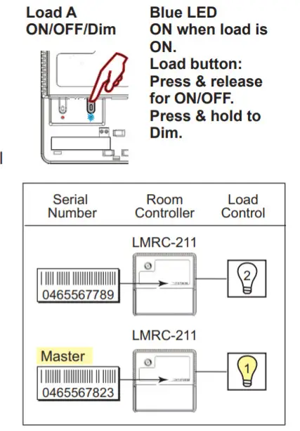
After the room controllers are connected to the DLM Local Network and powered up they automatically negotiate to determine which controller becomes the Master and the load numbers for each relay on the DLM Local Network.
The Master is the controller with the most load relays and the highest serial number. The LMRC-211 and the LMRC-211-347 Room Controllers each have one load relay.
In a DLM local network with only LMRC-211 or LMRC-211-347 Room Controllers, the Room Controller with the highest serial number is the Master, carrying Load 1. The next highest serial number would have Load 2, and so forth.
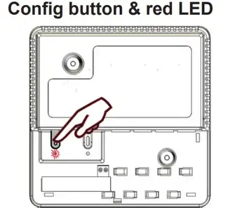
UNIT ADJUSTMENT – PUSH N’ LEARN (PNL)
Load Selection Procedure.
A configuration button (Config) allows access to our patented Push n’ Learn™ technology to change binding relationships between sensors, switches and loads.
Step 1 Enter Pushn’ Learn.
Press and hold the Config button (on any DLM device) for 3 seconds.
- The red LED on the Controller begins to blink. When you release the button, the red LEDs on other communicating devices connected to the DLM Local Network begin to blink. They continue to blink until you exit PnL mode.
- All loads in the room turn OFF immediately after entering PnL, then one load will turn ON. This is Load #1, which is bound to switch button #1 and occupancy sensors as part of the Plug n’ Go factory default setting. All switch buttons and sensors that are bound to this load have their blue LED solid ON.
Step 2 Load selection.
Press and release the Config button to step through the loads connected to the DLM Local Network. As each load turns ON note the devices (switch buttons and sensors) that are showing a bright solid blue LED. These devices are currently bound to the load that is ON.
The blue LED on the room controller or plug load controller connected to the load is also lit.
- To unbind a switch or dimmer button from a load, press the switch button while its blue LED is ON bright. The blue LED goes dim to indicate the button no longer controls the load that is currently ON.
- To unbind an occupancy sensor, press the up ( ▲) or down ( ▼) adjustment button while its blue LED is ON. The blue LED turns OFF to indicate the sensor no longer controls the load that is currently ON.
Pressing the switch or up ( ▲) or down ( ▼) button again while the load is ON rebinds the load to the button or sensor and the blue LED illuminates brightly.
Step 3 Exit Push n’ Learn.
Press and hold the Config button until the red LED turns OFF, approximately 3 seconds.
TROUBLESHOOTING
| LEDs on a switch or sensor don’t light. | 1. Check to see that the device is connected to the DLM Local Network. 2. Check for 24VDC input to the device: Plugin a different DLM device at the device location. If the device does not power up, 24VDC is not present. • Check the high voltage connections to the room controller and/or plug load controller(s). • If high voltage connections are good and high voltage is present, recheck DLM Local Network connections between the device and the room controller(s). |
| The wrong lights and plug loads are controlled. | 1. Configure the switch buttons and sensors to control the desired loads using the Push n’ Leam adjustment procedure. |
| LEDs turn ON and OFF but the load doesn’t switch. | 1. Make sure the DLM local network is not in PnL. 2. Check load connections to room controllers and/or plug load controllers. |
| Lamps do not dim, or lamps drop out at low dim levels. | 1. Make sure a 0-10V dimming ballast and rapid start sockets are installed per the ballast manufacturer’s recommendation. Shunted sockets are typically not acceptable. 2. Check to wire per ballast manufacturer’s instructions. |
This device complies with part 15 of the FCC Rules. Operation is subject to the following two conditions: (1)This device may not cause harmful interference, and (2) this device must accept any interference received, including interference that may cause undesired operation.
NOTE: This equipment has been tested and found to comply with the limits for a Class A digital device, pursuant to part 15 of the FCC Rules.
These limits are designed to provide reasonable protection against harmful interference when the equipment is operated in a commercial environment. This equipment generates, uses, and can radiate radio frequency energy and, if not installed and used in accordance with the instruction manual, may cause harmful interference to radio communications. Operation of this equipment in a residential area is likely to cause harmful interference in which case the user will be required to correct the interference at his own expense.
WARRANTY INFORMATION
Wattstopper warranties its products to be free of defects in materials and workmanship for a period of five (5) years. There are no obligations or liabilities on the part of Wattstopper for consequential damages arising out of, or in connection with, the use or performance of this product or other indirect damages with respect to loss of property, revenue, or profit, or cost of removal, installation or reinstallation.
![]() No. 23992 – 04/21 rev. 7
No. 23992 – 04/21 rev. 7
© Copyright 2021 Legrand All Rights Reserved.
© Copyright 2021 Tous droits réservés Legrand.
© Copyright 2021 Legrand Todos los derechos reservados.
800.879.8585
www.legrand.us/wattstopper