ENGINNERS ESP8266 NodeMCU Development Board

The Internet of Things (IoT) has been a trending field in the world of technology. It has changed the way we work. Physical objects and the digital world are connected now more than ever. Keeping this in mind, Espressif Systems (A Shanghai-based Semiconductor Company) has released an adorable, bite-sized WiFi-enabled microcontroller – ESP8266, at an unbelievable price! For less than $3, it can monitor and control things from anywhere in the world – perfect for just about any IoT project.
The development board equips the ESP-12E module containing ESP8266 chip having Tensilica Xtensa® 32-bit LX106 RISC microprocessor which operates at 80 to 160 MHz adjustable clock frequency and supports RTOS.
ESP-12E Chip
- Tensilica Xtensa® 32-bit LX106
- 80 to 160 MHz Clock Freq.
- 128kB internal RAM
- 4MB external flash
- 802.11b/g/n Wi-Fi transceiver
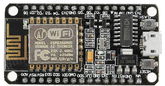
There’s also 128 KB RAM and 4MB of Flash memory (for program and data storage) just enough to cope with the large strings that make up web pages, JSON/XML data, and everything we throw at IoT devices nowadays. The ESP8266 Integrates 802.11b/g/n HT40 Wi-Fi transceiver, so it can not only connect to a WiFi network and interact with the Internet, but it can also set up a network of its own, allowing other devices to connect directly to it. This makes the ESP8266 NodeMCU even more versatile.
Power Requirement
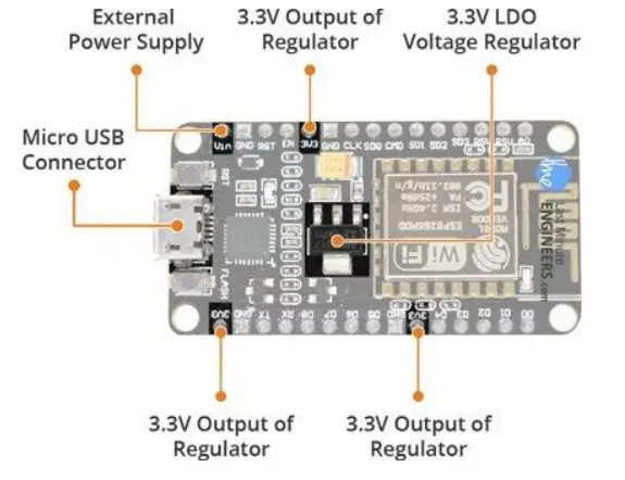
As the operating voltage range of ESP8266 is 3V to 3.6V, the board comes with a LDO voltage regulator to keep the voltage steady at 3.3V. It can reliably supply up to 600mA, which should be more than enough when ESP8266 pulls as much as 80mA during RF transmissions. The output of the regulator is also broken out to one of the sides of the board and labeled as 3V3. This pin can be used to supply power to external components.
Power Requirement
- Operating Voltage: 2.5V to 3.6V
- On-board 3.3V 600mA regulator
- 80mA Operating Current
- 20 μA during Sleep Mode
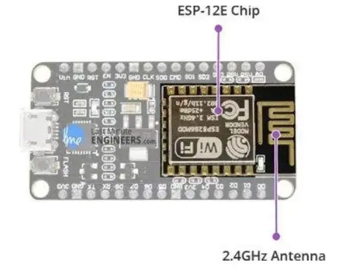
Power to the ESP8266 NodeMCU is supplied via the on-board MicroB USB connector. Alternatively, if you have a regulated 5V voltage source, the VIN pin can be used to directly supply the ESP8266 and its peripherals.
Warning: The ESP8266 requires a 3.3V power supply and 3.3V logic levels for communication. The GPIO pins are not 5V-tolerant! If you want to interface the board with 5V (or higher) components, you’ll need to do some level shifting.
Peripherals and I/O
The ESP8266 NodeMCU has total 17 GPIO pins broken out to the pin headers on both sides of the development board. These pins can be assigned to all sorts of peripheral duties, including:
- ADC channel – A 10-bit ADC channel.
- UART interface – UART interface is used to load code serially.
- PWM outputs – PWM pins for dimming LEDs or controlling motors.
- SPI, I2C & I2S interface – SPI and I2C interface to hook up all sorts of sensors and peripherals.
- I2S interface – I2S interface if you want to add sound to your project.
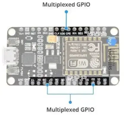
Multiplexed I/Os
- 1 ADC channels
- 2 UART interfaces
- 4 PWM outputs
- SPI, I2C & I2S interface
Thanks to the ESP8266’s pin multiplexing feature (Multiple peripherals multiplexed on a single GPIO pin). Meaning a single GPIO pin can act as PWM/UART/SPI.
On-board Switches and LED Indicator
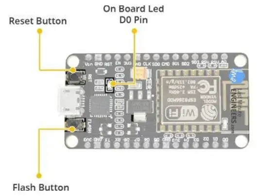
The ESP8266 NodeMCU features two buttons. One marked as RST located on the top left corner is the Reset button, used of course to reset the ESP8266 chip. The other FLASH button on the bottom left corner is the download button used while upgrading firmware.
Switches & Indicators
- RST – Reset the ESP8266 chip
- FLASH – Download new programs
- Blue LED – User Programmable
The board also has a LED indicator which is user programmable and is connected to the D0 pin of the board.
Serial Communication
The board includes CP2102 USB-to-UART Bridge Controller from Silicon Labs, which converts USB signal to serial and allows your computer to program and communicate with the ESP8266 chip.
Serial Communication
- CP2102 USB-to-UART converter
- 4.5 Mbps communication speed
- Flow Control support
If you have an older version of CP2102 driver installed on your PC, we recommend upgrading now.
Link for upgrading CP2102 Driver – https://www.silabs.com/developers/usb-to-uart-bridge-vcp-drivers
ESP8266 NodeMCU Pinout
The ESP8266 NodeMCU has total 30 pins that interface it to the outside world. The connections are as follows: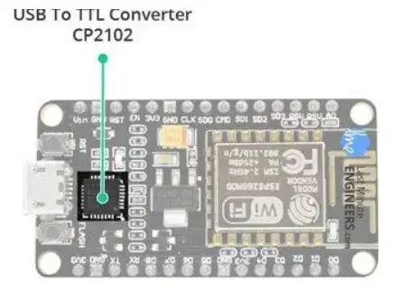
For the sake of simplicity, we will make groups of pins with similar functionalities.
Power Pins There are four power pins viz. one VIN pin & three 3.3V pins. The VIN pin can be used to directly supply the ESP8266 and its peripherals, if you have a regulated 5V voltage source. The 3.3V pins are the output of an on-board voltage regulator. These pins can be used to supply power to external components.
GND is a ground pin of ESP8266 NodeMCU development board. I2C Pins are used to hook up all sorts of I2C sensors and peripherals in your project. Both I2C Master and I2C Slave are supported. I2C interface functionality can be realized programmatically, and the clock frequency is 100 kHz at a maximum. It should be noted that I2C clock frequency should be higher than the slowest clock frequency of the slave device.
GPIO Pins ESP8266 NodeMCU has 17 GPIO pins which can be assigned to various functions such as I2C, I2S, UART, PWM, IR Remote Control, LED Light and Button programmatically. Each digital enabled GPIO can be configured to internal pull-up or pull-down, or set to high impedance. When configured as an input, it can also be set to edge-trigger or level-trigger to generate CPU interrupts.
ADC Channel The NodeMCU is embedded with a 10-bit precision SAR ADC. The two functions can be implemented using ADC viz. Testing power supply voltage of VDD3P3 pin and testing input voltage of TOUT pin. However, they cannot be implemented at the same time.
UART Pins ESP8266 NodeMCU has 2 UART interfaces, i.e. UART0 and UART1, which provide asynchronous communication (RS232 and RS485), and can communicate at up to 4.5 Mbps. UART0 (TXD0, RXD0, RST0 & CTS0 pins) can be used for communication. It supports fluid control. However, UART1 (TXD1 pin) features only data transmit signal so, it is usually used for printing log.
SPI Pins ESP8266 features two SPIs (SPI and HSPI) in slave and master modes. These SPIs also support the following general-purpose SPI features:
- 4 timing modes of the SPI format transfer
- Up to 80 MHz and the divided clocks of 80 MHz
- Up to 64-Byte FIFO
SDIO Pins ESP8266 features Secure Digital Input/Output Interface (SDIO) which is used to directly interface SD cards. 4-bit 25 MHz SDIO v1.1 and 4-bit 50 MHz SDIO v2.0 are supported.
PWM Pins The board has 4 channels of Pulse Width Modulation (PWM). The PWM output can be implemented programmatically and used for driving digital motors and LEDs. PWM frequency range is adjustable from 1000 μs to 10000 μs, i.e., between 100 Hz and 1 kHz.
Control Pins are used to control ESP8266. These pins include Chip Enable pin (EN), Reset pin (RST) and WAKE pin.
- EN pin – The ESP8266 chip is enabled when EN pin is pulled HIGH. When pulled LOW the chip works at minimum power.
- RST pin – RST pin is used to reset the ESP8266 chip.
- WAKE pin – Wake pin is used to wake the chip from deep-sleep.
ESP8266 Development Platforms
Now, let’s move on to the interesting stuff! There are a variety of development platforms that can be equipped to program the ESP8266. You can go with Espruino – JavaScript SDK and firmware closely emulating Node.js, or use Mongoose OS – An operating system for IoT devices (recommended platform by Espressif Systems and Google Cloud IoT) or use a software development kit (SDK) provided by Espressif or one of the platforms listed on WiKiPedia. Fortunately, the amazing ESP8266 community took the IDE selection a step further by creating an Arduino add-on. If you’re just getting started programming the ESP8266, this is the environment we recommend beginning with, and the one we’ll document in this tutorial.
This ESP8266 add-on for Arduino is based on the amazing work by Ivan Grokhotkov and the rest of the ESP8266 community. Check out the ESP8266 Arduino GitHub repository for more information.
Installing the ESP8266 Core on Windows OS
Let’s proceed with installing ESP8266 Arduino core. The first thing is having latest Arduino IDE (Arduino 1.6.4 or higher) installed on your PC. If don’t have it, we recommend upgrading now.
Link for Arduino IDE – https://www.arduino.cc/en/software
To begin, we’ll need to update the board manager with a custom URL. Open up Arduino IDE and go to File > Preferences. Then, copy below URL into the Additional Board Manager URLs text box situated on the bottom of the window: http://arduino.esp8266.com/stable/package_esp8266com_index.json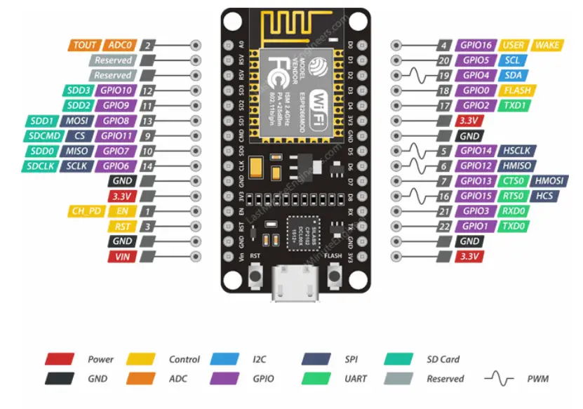
Hit OK. Then navigate to the Board Manager by going to Tools > Boards > Boards Manager. There should be a couple new entries in addition to the standard Arduino boards. Filter your search by typing esp8266. Click on that entry and select Install.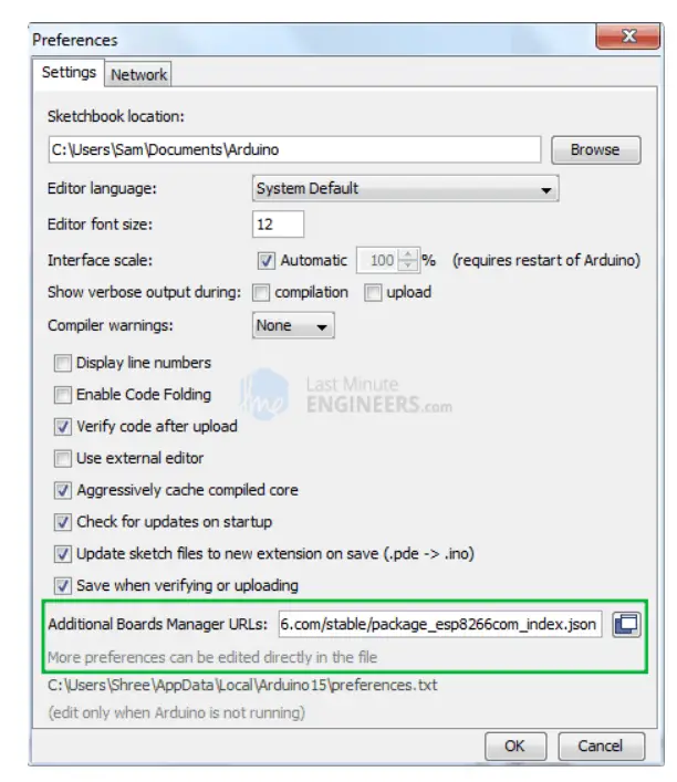
The board definitions and tools for the ESP8266 include a whole new set of gcc, g++, and other reasonably large, compiled binaries, so it may take a few minutes to download and install (the archived file is ~110MB). Once the installation has completed, a small INSTALLED text will appear next to the entry. You can now close the Board Manager
Arduino Example: Blink
To make sure ESP8266 Arduino core and the NodeMCU are properly set up, we’ll upload the simplest sketch of all – The Blink! We will use the on-board LED for this test. As mentioned earlier in this tutorial, D0 pin of the board is connected to on-board Blue LED & is user programmable. Perfect! Before we get to uploading sketch & playing with LED, we need to make sure that the board is selected properly in Arduino IDE. Open Arduino IDE and select NodeMCU 0.9 (ESP-12 Module) option under your Arduino IDE > Tools > Board menu.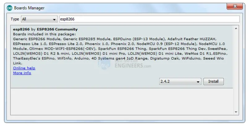
Now, plug your ESP8266 NodeMCU into your computer via micro-B USB cable. Once the board is plugged in, it should be assigned a unique COM port. On Windows machines, this will be something like COM#, and on Mac/Linux computers it will come in the form of /dev/tty.usbserial-XXXXXX. Select this serial port under the Arduino IDE > Tools > Port menu. Also select the Upload Speed : 115200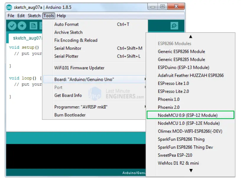
Warning: More attention needs to be given to selecting board, choosing COM port and selecting Upload speed. You may get espcomm_upload_mem error while uploading new sketches, if failed to do so.
Once you are done, try the example sketch below.
void setup()
{pinMode(D0, OUTPUT);}void loop()
{digitalWrite(D0, HIGH);
delay(500);
digitalWrite(D0, LOW);
delay(500);
Once the code is uploaded, LED will start blinking. You may need to tap the RST button to get your ESP8266 to begin running the sketch.