intel MAG-15 eluktronics User Guide
In Collaboration with
Preparing your Computer
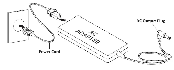
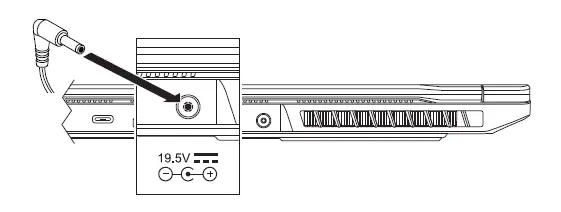
Connect the power cord to the AC adapter then to a grounded 100-240VAC outlet.

Connect the AC adapter’s DC output plug to the DC IN jack on the back of the system.
Preparing your Computer
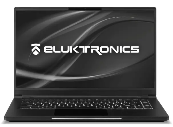
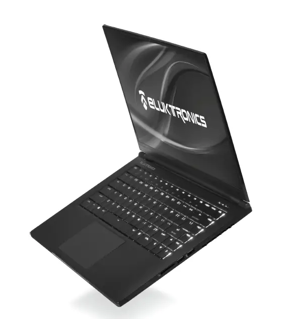
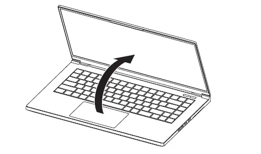
The display panel can be opened to a wide range of angles for optimal viewing.
 Attempting to force the lid open beyond 145 degrees will cause damage ill to the hinges and/or the display.
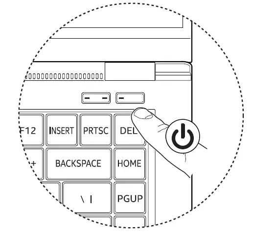
Press the power button to turn on your notebook computer.

Product Overview
Product Overview
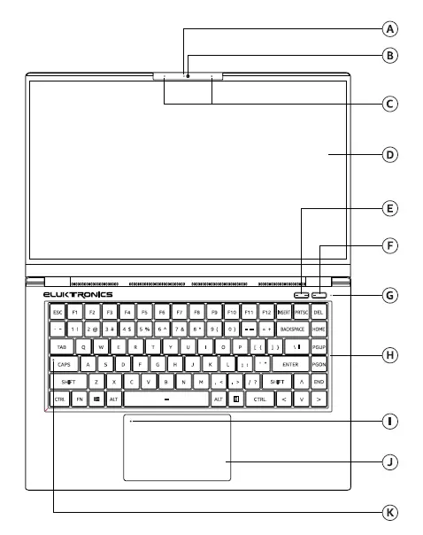
A Camera Status LED Indicator will turn blue when the camera is active
B Camera High definition infrared camera
C Digital Microphones Dual built-in microphones
D LCD Screen Internal display/panel
E Mode Button Selects operating mode when the laptop is powered on: Battery Saver – Both Indicators are off Balanced – Left indicator is on Performance – Both indicators are on
F Power Button Press once to turn the laptop on when it powered off or asleep. Indicator will turn on. Press once to notify the operating system to power off the laptop or enter sleep mode. Indicator will turn off if powered off or blink for sleep mode.
G Battery Status Indicator Indicator will blink when charging the battery Indicator will turn amber when the battery level is low Indicator will turn solid when the battery is fully charged
H Keyboard Mechanical keyboard with RBG backlight support that may be controlled through the Control Center utility
I (D Touchpad Enable/Disable Switch with Indicator
Double tap to enable or disable the touchpad. Indicator will turn on when the touch pad is disabled.
J Touchpad/Clickpad
I Touch-sensitive pointing device which functions like a mouse
K Caps Lock Status Indicator Caps Lock ON: Indicator On Caps Lock OFF: Indicator Off
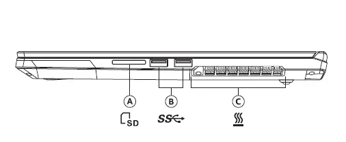
Right Side
A 2 in 1 Card Reader
Support for SD/SDHC/SDXC memory cards
B USB 3.1 Gen1 Ports
Connect any USB devices into these ports, such as a USB flash drive, keyboard, or mouse
C Vents
The thermal vents are designed to cool the internal components and avoid overheating 6
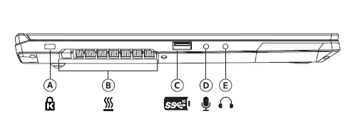
Left Side
A Kensington Lock
Anti-theft key lock hole
B Vents
The thermal vents are designed to cool the internal components and avoid overheating
C USB 3.1 Gen2 Port
Connect any USB device into this port, such as a USB flash drive, keyboard, or mouse. This port can also be used as a charging port.
D Microphone Jack
Connect a microphone into this jack
E Headphone Jack
Connect amplified speakers or headphones into this jack
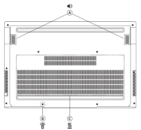
Bottom Side
A Speakers
Stereo audio output
B Back Cover Screws
You can remove the screws to install or remove the SO-DIMMs and M.2 SSD cards.Modification of any other parts or components aside from the SO-DIMMs or M.2 SSD cards will void your warranty
C Vents
The thermal vents are designed to cool the internal components and avoid overheating
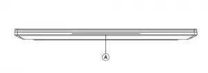
Front Side
A RGB Light Bar
May be controlled through the Control Center utility
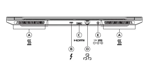
Back Side
A vents
The thermal vents are designed to cool the internal components and avoid overheating
B Thunderbolt™ 3 Port
Connect any USB Type C or Thunderbolt device into this port, such as a USB Flash drive or an external storage device. This port will also support displays using a Type-C to DisplayPort cable.
C HDMI Port
Supports high-definition digital video connections
D Network Jack (RJ-45)
This jack lets you connect to a Local Area Network (LAN)
E Power Connector
Connect the AC adapter into this connector
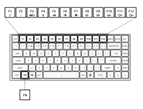
Understanding the Keyboard
The following defines the row of function keys which also contain a secondary hotkeys/shortcuts which can be accessed by pressing and holding down the
Function Key (FN) while simultaneously pressing the desired hotkey/shortcut.
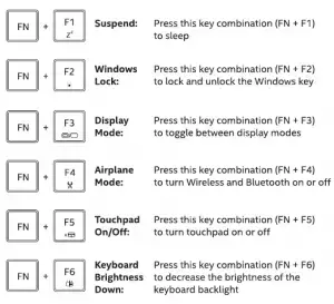
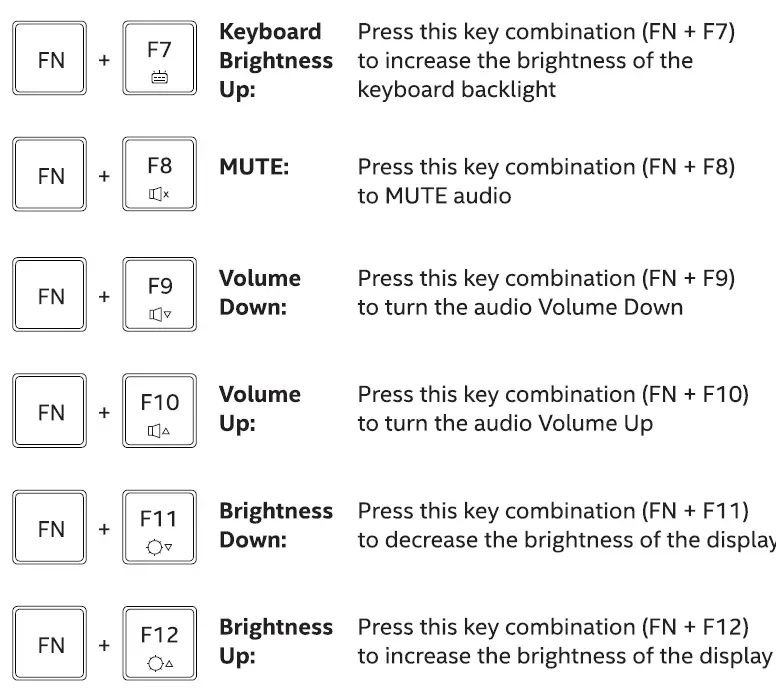
Keyboard Shortcuts
To activate these functions, press the hotkey associated with the desired function as indicated below:
Keyboard Shortcuts
Using the Touchpad/Clickpad
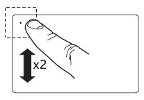
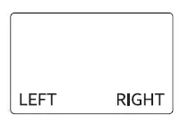
The touch pad / clickpad is a rectangular electronic panel located just below your keyboard. Clicking twice within the 15mm x 15mm corner in the top left will enable or disable (lighted indicator) touchpad functionality. You can use the static-sensitive panel of the touch pad / clickpad and slide it to move the cursor. You can use the buttons below the touch pad as left and right mouse buttons. Press the left and right bottom corners located on the bottom edge of the touchpad / clickpad to make selections and run functions. These two buttons are similar to the left and right buttons on a mouse. Tapping on the touchpad / clickpad produces similar results.
Click twice here to enable or disable the touch pad
Use these bottom corners similar to mouse buttons
Using Control Center
Control Center is an application for customizing the laptop functionality. To launch, click the Control Center icon that is on the desktop or in the tray.
When Control Center opens it will default to the last windows accessed. Select the other available options by clicking on one of the icons on the left side of the window. Below are descriptions of the options available in each window.
EZSwitch
- Keyboard Backlight: The default is on. Click the toggle to turn the keyboard backlight off and on.
- LED Light Bar: The default is on. Click the toggle to turn the LED Light Bar off and on.
- Turn Off Display: Turns off the internal display. Touching mouse, touch pad or any key will turn the display back on.
- Display Mode: Select profiles for the display mode and quickly switch between them.
- Windows Key Lock: Select on to disable the Windows key, select off to enable the Windows key.
- Function Key On-Screen Display: Select on to enable the Function key, select off to disable the Function key.
Keyboard Backlight Settings
Use these options to set the color and behavior of the keyboard backlight. Preset modes and effects are available. Use the keyboard layout to customize the effect by individual keys are sets of keys.
- Enable Keyboard Backlight: The default is on. Click the toggle to turn the keyboard backlight off and on.
- Keyboard Backlight Wizard: This allows up to 5 different profiles to be saved for the keyboard backlight.
- Plugged In – Set the behavior of the keyboard backlight LEDs while the device is plugged in.
- On Battery – Set the behavior of the keyboard backlight LEDs while the device is on battery.
- Effect: – Select from a preset list of effects for the keyboard backlight or customize one. Effect settings allows adjustments for brightness, speed and direction of the keyboard backlight effect.
Using Control Center
LED Light Bar Settings
Use these options to set the color and behavior of the LED Light Bar.
- Enable LED Light Bar: The default is on. Click the toggle to turn the LED Light Bar off and on.
- Plugged In: Set the mode for the LED Light Bar when the power adapter is plugged in.
- On Battery: Set the mode for the LED Light Bar when running on battery
- RGB Color Bars: Use these 3 bars to adjust the color of the LED Light Bar
- Colorful: Check the box to disable use of the RGB sliding color bars.
Power Settings
Use the options to customize power and fan modes.
- System Power Mode: Use the options shown to set the power mode of the system
- Fan Mode: Use the options shown to set the fan mode.
System Monitor
This is an information screen only. Use it to reference system information.
Remove Back Cover
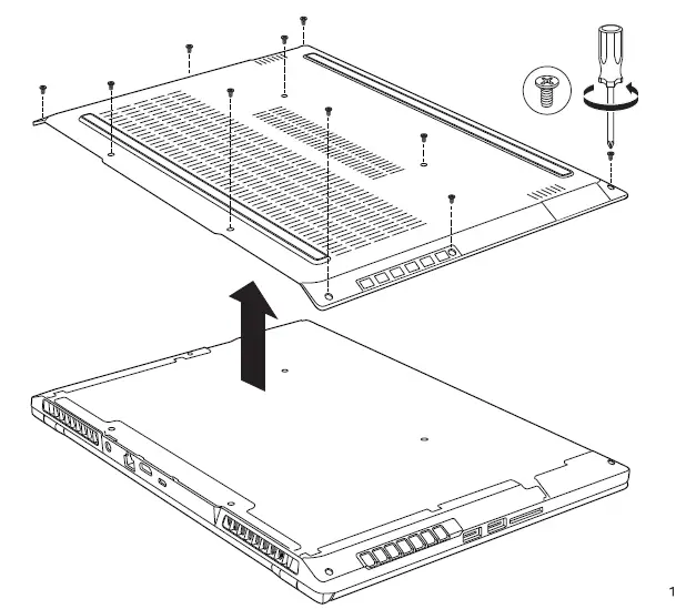
 Do not remove or replace the back cover with the power on. Always turn off the power and unplug the power cord from the system before removing or replacing the back cover. Otherwise, the system could be
damaged.
To remove the back cover, remove the 10 screws securing the cover to the chassis.
Be careful when removing the back cover as it can be bent very easily. Lift at the back first, then start at one of the front corners and lift gently to remove the back cover from the clips, then continue to remove the back cover from the front clips. Once the back cover is removed from the clips it can be lifted off.
Inside View
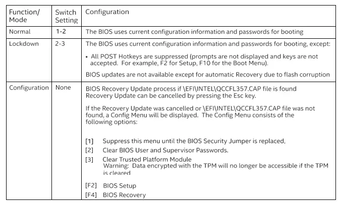
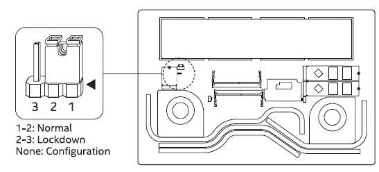
BIOS Security Jumper
 Do not change the jumper with the power on. Always turn off the power and unplug the power cord from the system before changing a jumper
setting. Otherwise, the system could be damaged.
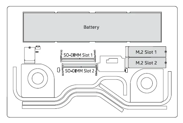
Install Memory
 Do not add or remove memory with the power on. Always turn off the ill power and unplug the power cord from the system before adding or
removing memory. Otherwise, the system could be damaged.
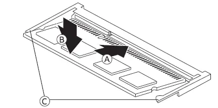
Two slots are available for an 50-DIMM. Insert the 50-DIMM into the connector at an angle (A}, then push down (B} until both latching mechanisms (C} secure the edges of the 50-DIMM.
The memory modules and the corresponding 50-DIMM slots are keyed. To reduce risk of damage, please take caution to properly align the key on the memory module before fully inserting and latching into place.
Both 50-DIMM slots can be populated for higher performance dual channel memory operation.’
Install Storage
 Do not add or remove storage with the power on. Always turn off the ill power and unplug the power cord from the system before adding or
removing storage. Otherwise, the system could be damaged.
NOTE: M.2 Slot 1 will support SATA and NVMe. M.2 Slot 2 will only support NVMe.
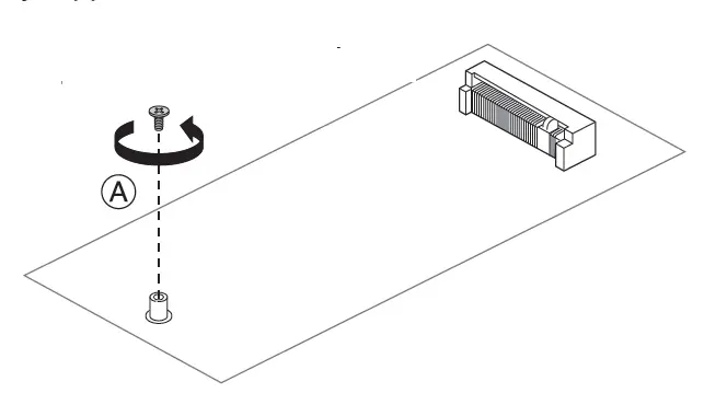
Two slots are available for an 80mm M.2 SSD card. First, remove the screw from the threaded standoff

Insert the M.2 card into the connector at an angle as shown. Take caution to properly align the notch on the M.2 card with the key in the connector
to reduce risk of damage.
Push the M.2 card down and re-install screw into standoff to secure.
Disclaimer
INFORMATION IN THIS DOCUMENT IS PROVIDED IN CONNECTION WITH INTEL”‘ PRODUCTS. NO LICENSE, EXPRESS OR IMPLIED, BY ESTOPPEL OR OTHERWISE, TO ANY INTELLECTUAL PROPERTY RIGHTS IS GRANTED BY THIS DOCUMENT. EXCEPT AS PROVIDED IN INTEL’S TERMS AND CONDITIONS OF SALE FOR SUCH PRODUCTS, INTEL ASSUMES NO LIABILITY WHATSOEVER, AND INTEL DISCLAIMS ANY EXPRESS OR IMPLIED WARRANTY, RELATING TO SALE AND/OR USE OF INTEL PRODUCTS INCLUDING LIABILITY OR WARRANTIES RELATING TO FITNESS FORA PARTICULAR PURPOSE, MERCHANTABILITY, OR INFRINGEMENT OF ANY PATENT, COPYRIGHT OR OTHER INTELLECTUAL PROPERTY RIGHT.
Intel products are not intended for use in medical, life saving, or life sustaining applications. Intel may make changes to specifications and product descriptions at any time, without notice. Intel products may contain design defects or errors known as errata which may cause the product to deviate from published specifications. Current characterized errata are available on request. The SuperSpeed USB Trident”‘ logo is a registered trademark owned by USB Implementers Forum, Inc. and any use of such mark by Intel Corporation is under license. The terms HDMI and HDMI High-Definition Multimedia Interface, and the HDMI Logo are trademarks or registered trademarks of HDMI Licensing LLC in the United States and other countries. Intel and the Intel logo are trademarks of Intel Corporation in the United States and/or other countries.
* Other names and brands may be claimed as the property of others. Copyright© 2019, Intel Corporation. All rights reserved.]