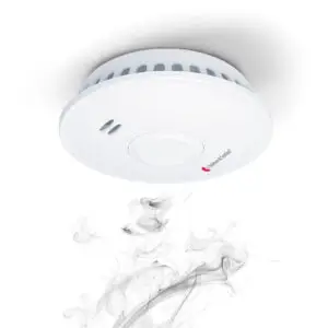

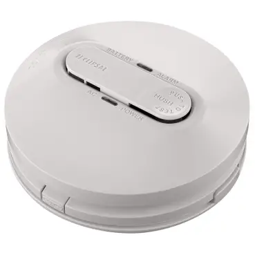
CLIPSAL FIRETEK 755RB Smoke Alarm Mounting Base with Integrated Relay
Scan the QR code for more information about your Clipsal smoke alarm:
- What smoke alarms can and cannot do
- Developing and practicing a plan of escape
- What to do if an alarm sounds.
Operating Elements
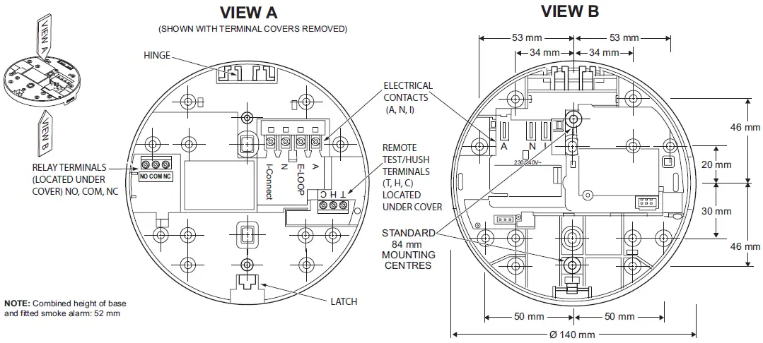
Installation
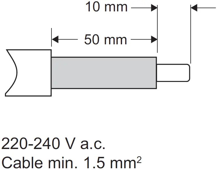
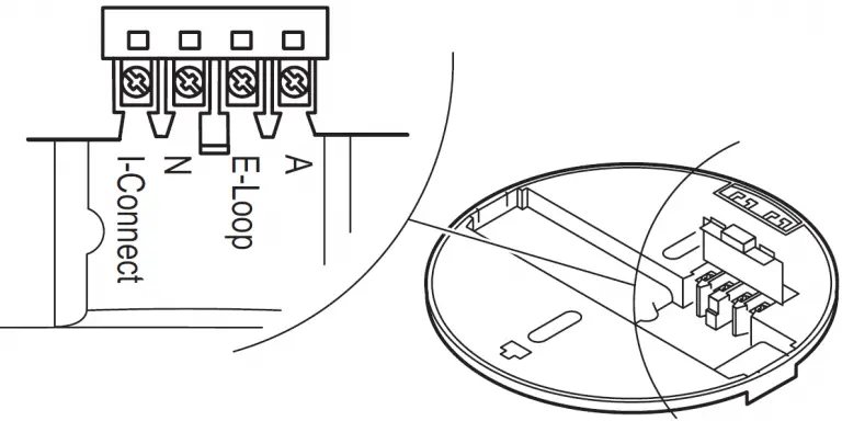
- Strip the active, neutral and interconnect (if used) wires back to the strip length shown here.
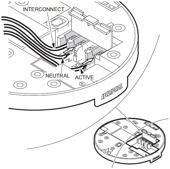
- Connect wires to terminals on the base and ensure the screws are fully tightened.
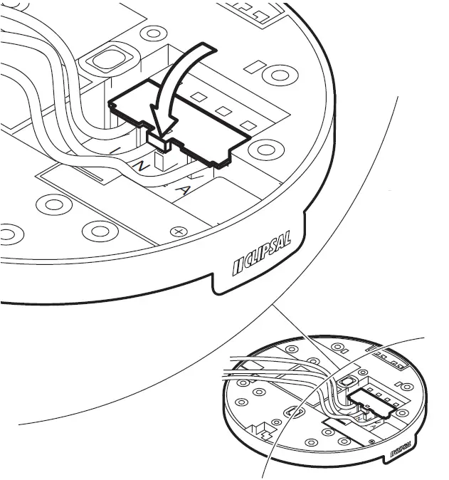
- Clip terminal cover closed to avoid contact with live terminals.
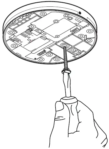
- Screw the base on to the ceiling.
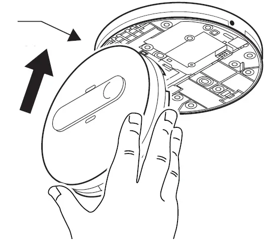
- Clip the smoke alarm into the base at the hinge.
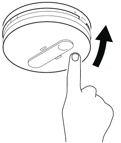
- Use gentle pressure to latch the smoke alarm onto the base (take care to align the pins and terminals).
 Note: When 755PSMA2/4 alarms are used ensure the 9V battery is fitted prior to mounting.
Interconnecting Smoke Alarms
Terminal markings:
A: Active/Line (Red)
E-Loop: Earth Wire
N: Neutral (Black)
I-Connect: Interconnect
Relay Operation and Configuration
Remote Test/Hush Feature
General Information
- Leave these instructions with the occupant, to be retained for the life of the product.
- The smoke alarm base must be installed by a licensed electrician.
Compatibility
This product is compatible with the following Clipsal Smoke alarms:
- 755RLPSMA2
- 755RLPSMA4
- 755PSMA2
- 755PSMA4
For Your Safety
RISK OF ELECTRIC SHOCK, EXPLOSION OR ARC FLASH
- This product must only be installed and serviced by appropriately qualified and/or licensed electrical personnel.
- This product must only be used for the purpose described in these instructions and must be installed in accordance with the wiring rules and regulations in that location.
- Isolate the electrical supply before doing any work on this product.
- Ensure the product has been correctly installed and tested for safe operation before reconnecting the electrical supply.
Failure to follow these instructions will result in death or serious injury.
CAUTION
EQUIPMENT INSTALLATION HAZARD
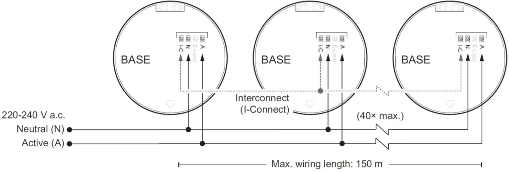
- All interconnected smoke alarms (max 40) must be supplied from the same interconnection. A common Neutral must be used for the interconnect to operate.
- DO NOT connect the interconnect wire to Active or Neutral.
- Do not connect to a circuit which also has inductive loads connected. Spikes generated by switching inductive loads may damage electrical components within the base or connected smoke alarm.
- Do not open this base, as there are no user-serviceable parts inside.
Failure to follow these instructions may result in injury or equipment damage.
Choosing the Installation Location
EQUIPMENT INSTALLATION COMPLIANCE
This product must be installed in accordance with the National Construction Code and any local state legislation requirements.
Failure to follow these instructions may result in a non-compliant installation.
Installation
- Only install the product indoors in a stand-alone or wired interconnected set up (see Interconnecting smoke alarms).
- Do not attach to surfaces which are damp, freshly painted or otherwise electrically conductive (e.g. metallic surfaces).
Mounting and connecting the smoke alarm
Follow the illustrations:
- Turn on the mains power and check:
- The green LED illuminates to show active connection to power.
- The red LED pulses every 40 seconds to show correct operation.
- Press Test/Hush to check smoke alarm functions.
Interconnecting Smoke Alarms
Always test operation after adding or removing smoke alarms to an interconnection setup.
Relay Operation and Configuration
Global/Local Relay Setting
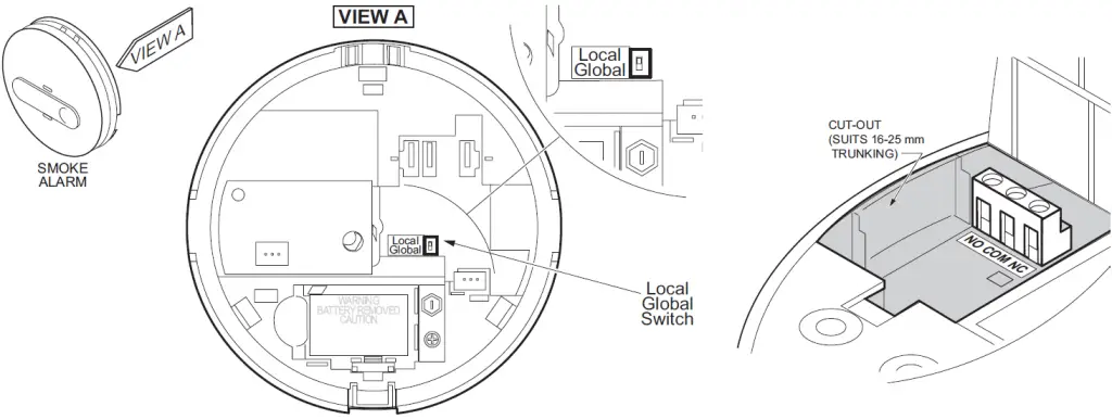
The 755 series smoke alarms have a Global/Local switch for use with 755RB mounting base only.
When the Global/Local switch is set to Local, only activation of the connected alarm will operate the relay.
When the Global/Local switch is set to Global, activation of any smoke alarm that is interconnected with the base causes the relay to operate.
The default setting is Global.
Relay Operation
When the smoke alarm is triggered, the relay on the relay base will operate according to the description in Global/Local Relay Setting both when mains or backup battery power is applied.
Relay Output Connection
For connecting auxiliary devices, the relay mounting base terminal specifications are:
- NO (Normally Open)
- COM (Common)
- NC (Normally Closed).
- Wiring capacity 2 × 1.5 mm2 each
- Combination screw head type.
- Voltage-free and segregated from the mains supply terminal connections with a physical barrier.
- Relay rating is 250 V a.c., 2 A.
Remote Test/Hush Function
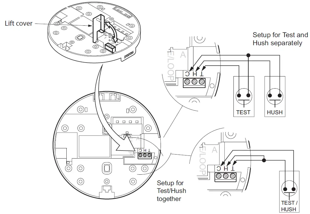
The Remote Test/Hush feature is controlled by the smoke alarm. Bases provide optional connection for remote test/hush buttons (dry contact momentary remote switches e.g. Clipsal bell press switches).
Connection Options for Remote Test/Hush Buttons
- Connect remote buttons as either separate Test and Hush buttons, or as single Test/Hush button.
- Wiring capacity of each terminal is 2×1.5 mm2 cables.
- Terminal screws are combination screw head type.
- Max. cable length to Remote Test/Hush switch is 20 m.
Test Function – When No Smoke Present
Test the LOCAL Smoke Alarm
Press and hold either the Remote Test button or the Local Test/Hush button and release within 4 seconds. Only the local smoke alarm will sound.
Test the LINKED Smoke Alarms
Press and hold either the Remote Test button or the Local Test/Hush button for more than 5 seconds. The linked alarms will sound.
Hush Function – When Smoke Present
To hush a smoke alarm, identify the unit which has triggered by the flashing red LED (Unit will not silence if it does not have a flashing red LED.) Press and hold the local Test/Hush button or the remote hush button for 40 seconds. All smoke alarms that are interconnected will also fall silent.
If multiple interconnected alarms have detected smoke and are flashing red LEDs, then press the Remote Hush button or the local Test/Hush button on each alarm to silence them.
Technical Data
| Mains Power Source | 220-240 V a.c., 50 Hz |
| Operating Temperature | 0 °C to 45 °C |
| Ambient Humidity | 5% to 95% |
| Interconnecting | Max 40 alarms (wired over 150 m) |
| Terminal Provisions | Active, Neutral, Loop and Interconnect terminals, each accommodates 2 × 1.5 mm2 |
| Relay Rating | 250 V a.c., 2 A |
| Relay Contacts | NO/COM/NC voltage free contacts |
| Remote Input | Dry contact momentary switch (for Remote Test/Hush function) |
| Approvals | Activfire RCM |
| Complies with | AS/NZS 60065, AS/NZS 60950.1 |
Trademarks and Certifications
Schneider Electric acknowledges that the Australian Standard Certified Product logo is a trademark of SAI Global, and that the Activfire Certified logo is a trademark of CSIRO.

Warranty
We warrant this product to be free from defects in materials and workmanship for a period of 5 (five) years from the date of installation.
Customer Care
If you have technical questions, please contact the Customer Care Centre in your country.
Australia
Schneider Electric (Australia) Pty Ltd Customer Care Australia: 13 73 28
Email: [email protected]
www.schneider-electric.com.au
New Zealand
Schneider Electric (NZ) Ltd
After Hours Service: 0800 735 4357 (NZ only) Customer Care NZ: 0800 652 999
Email: [email protected]
www.schneider-electric.com

