![]()
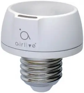
SD-102
Lightbulb Dimmer socket
Quick Installation Guide
01 Introduction
Transform any home into a smart home with the SD-102 Z-Wave Smart Dimmer Socket. The dimmer socket can be easily adapted to your current lighting devices, uses your existing lamp, and provides Z-Wave wireless and with remote control of overhead lighting. Use the dimmer feature to customize the lighting output and create the perfect ambiance for any room. Providing ultimate flexibility, the Z-Wave Smart Dimmer Socket allows you to operate the lighting by itself or easily integrate the socket with two-way, three-way or four-way wiring configurations by adding the Smart Switch Modules for Z-Wave. Take control of your home lighting with Z-Wave Smart Lighting Controls!
02 Key Features -1
Easily adapt to any standard lamp socket with the Z-Wave Smart Dimmer Socket to turn lighting on/off or adjust dim levels with your mobile device or computer using any Z-Wave certified gateway
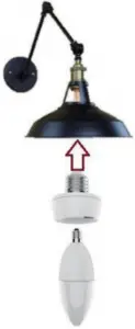
- Includes E14 (male) to E27 (female) converter adapter that will match most standard lamp socket
- Can be controlled in groups of multiple lights or used to create dimmable ambient interior lighting scenes
03 Key Features -2
- Provides ultimate flexibility – use by itself or with the switch modules in three, four, five and six-way wiring configurations (Switch Module is required for multi-switch applications)
- Screw installation provides improved space efficiency when adapting existing lamp socket.
Compatible with any Z-Wave certified gateway, providing access from many popular home automation systems and applications (application software not included)
04 Include Smart Dimmer Socket
Screw the lampholder to the lamp and power lamp on. Device will automatically be in inclusion mode.
If device is not in inclusion mode, press include/exclude button three times.

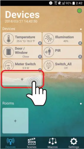
05 Include Smart Dimmer Socket
Open AirLive Smart Lite APP Plus in your phone to add the sensors.
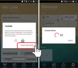
- Go to Devices page and click “”+”” icon.
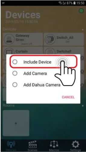
- Press Include Device
06 Include Smart Dimmer Socket
- Press “START INCLUSION”
- Start to include a device.
07 Include Smart Dimmer Socket
When the device is being included, APP will configure the setting into gateway.
08 Choosing a Suitable Location
- Do not locate the dimmer facing direct sunlight, humid or dusty place.
- The suitable ambient temperature for the Switch is 0°C~40°C.
- Do not locate the dimmer where exists combustible substances or any source of heat, e.g. fires, radiators, boiler etc.
- After putting it into use, the body of dimmer will become a little bit hot of which phenomenon is normal.
09 LED Indication
- Normal: Whenever we switch On and off of the SD-102 by On/Off button or RF command, the LED will lights up when switch on; whereas LED off when switch off.
- No node ID: Under normal operation, when the Switch has not been allocated a node ID, the LED flashes on and off alternately at 2-second intervals. By pressing On/Off button, it will stop flashing temporarily.
- Learning: When SD-102 is in learning mode, LED flashes on and off alternately and repeatedly at 0.5 second intervals
10 Manual dim level control
To manually switch on the light, press and release the On/Off button shortly when the light is off. The light will dim from off to the level which was set before switch off.
To manually switch off the light, press and release the On/Off button shortly when the light is on.
To adjust the dim level, press and hold the On/Off button until the desired dim level is achieved, then release.
FCC Interference Statement
This equipment has been tested and found to comply with the limits for a Class B digital device, pursuant to Part 15 of the FCC Rules. These limits are designed to provide reasonable protection against harmful interference in a residential installation.
This equipment generates, uses and can radiate radio frequency energy and, if not installed and used in accordance with the instructions, may cause harmful interference to radio communications.
However, there is no guarantee that interference will not occur in a particular installation.
If this equipment does cause harmful interference to radio or television reception, which can be determined by turning the equipment off and on, the user is encouraged to try to correct the interference by one of the following measures:
- Reorient or relocate the receiving antenna.
- Increase the separation between the equipment and receiver.
- Connect the equipment into an outlet on a circuit different from that to which the receiver is connected.
- Consult the dealer or an experienced radio/TV technician for help.
This device complies with Part 15 of the FCC Rules. Operation is subject to the following two conditions:
(1) This device may not cause harmful interference, and
(2) This device must accept any interference received, including
interference that may cause undesired operation.
FCC Caution: Any changes or modifications not expressly approved by the party responsible for compliance could void the user’s authority to operate this equipment.
This transmitter must not be co-located or operating in conjunction with any other antenna or transmitter.
Warning
Do not dispose of electrical appliances as unsorted municipal waste, use separate collection facilities.
Contact your local government for information regarding the collection systems available.
If electrical appliances are disposed of in landfills or dumps, hazardous substances can leak into the groundwater and get into the food chain, damaging your health and well-being.
When replacing old appliances with new once, the retailer is legally obligated to take back your old appliance for disposal at least for free of charge.
RF Exposure Information (SAR)
This device meets the government’s requirements for exposure to radio waves. This device is designed and manufactured not to exceed the emission limits for exposure to radio frequency (RF) energy set by the Federal Communications Commission of the U.S. Government. The exposure standard employs a unit of measurement known as the Specific Absorption Rate, or SAR. The SAR limit set by the FCC is 1.6 W/kg. Tests for SAR are conducted using standard operating positions accepted by the FCC with the EUT transmitting at the specified power level in different channels.
The FCC has granted an Equipment Authorization for this device with all reported SAR levels evaluated as in compliance with the FCC RF exposure guidelines. SAR information on this device is on file with the FCC and can be found under the Display Grant section of www.fcc.gov/eot/ea/fccid after searching on FCC ID: ODMSG101