ALL-PRO Cooper Lighting MS34
PACKAGING CONTENTS
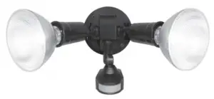
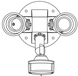
A. Motion detector and light fixture
B. Coverplate gasket

C. (2) Lampholder gaskets

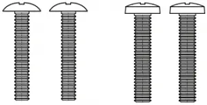
D. (2) #6 and (2) #8 mounting screws (use the size that fits your junction box)
E. (2) Wire nuts

ITEMS REQUIRED
(Purchase separately)
- Phillips screwdriver
- Hammer
- Outdoor weatherproof silicone caulking
- (2) 150 watt (MAX) PAR 38 floodlight bulbs
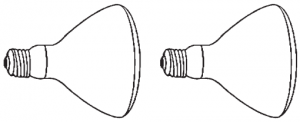

NOTE: This fixture was designed to work with up to 150 watt maximum PAR halogen flood bulbs. For improved energy efficiency, lower wattage PAR halogen flood bulbs may be used.
Compact Fluorescent (CFL) bulbs contain electronics which may interfere with the motion sensing function of your fixture and are not recommended.
HOW IT WORKS
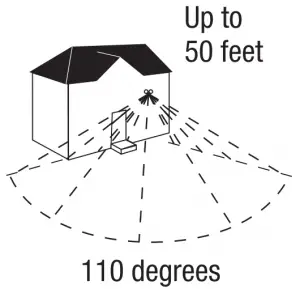
Your motion activated floodlight senses heat images from objects such as people, large animals and automobile engines.
When motion is detected, the lights will automatically turn on. Once motion has stopped, the lights will turn off after a preselected time delay. Your motion activated floodlight may also be used as a standard floodlight.
IMPORTANT SAFETY INSTRUCTIONS
When using product, basic precautions should always be followed, including the following:
- Heed all warnings, including below warnings AND those included on product.
- Save these instructions and warnings.
- For outdoor use only.
- cULus LISTED for wet location.
- Disassembly of your fixture will void the warranty.
- Your fixture is prewired and preassembled for easy installation.

- Read and follow these instructions.
- To reduce the risk of a burn during relamping, disconnect power supply to the unit before relamping.
- Always use or replace bulb with the same wattage or lower wattage than required. Installing a bulb of a higher wattage could create a fire hazard and will void the warranty.
CAUTION
- Connect fixture to a 120 volt, 60 Hz power source. Any other connection voids the warranty.
- Mount fixture to a grounded, recessed-mounted standard junction box marked for use in wet locations.
- NOT suitable for ground mount installation.
- Fixture should be installed by persons with experience in household wiring or by a qualified electrician. The electrical system, and the method of electrically connecting the fixture to it, must be in accordance with the National Electrical Code and local building codes.
- Do not allow sensor head to touch light housing – maintain at least 1 in. space between fixture and sensor.
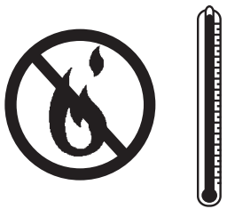
- Keep away from flammable objects. Do not position fixture within 2 in. of any combustible materials.
- For proper operation and protection against damage, the motion sensor head adjustment knobs must be facing the ground.

SAVE THESE INSTRUCTIONS.
FOR BEST RESULTS
- Install the motion sensor/transmitter 8-12 feet above the ground. (Motion sensor is less sensitive above 12 feet.)
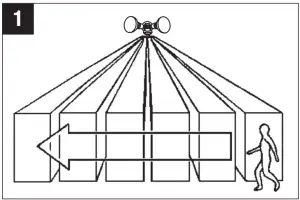
- Locate motion sensor so motion moves across detection zone (Fig. 1).
- Locate sensor away from heat producing sources to prevent false triggering. Also be very careful not to include objects such as windows, white walls and water in the detection zone.
- Locate sensor away from moving objects such as trees, large shrubs and street traffic.
- Do not install more than one motion activated floodlight on one wall switch or the same circuit since this may cause interference between fixtures.
MOUNTING AND WIRING YOUR FIXTURE
WARNING: Risk of electric shock. Disconnect power at fuse or circuit breaker before installing or servicing.
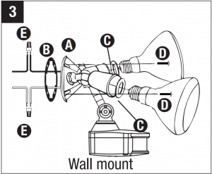
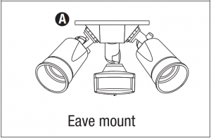
NOTE: Fixture can be wall or eave mounted.
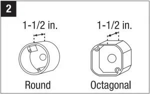
NOTE: Coverplate mounts to recessed mounted standard junction boxes (Fig. 2). Junction box must be at least 1-1/2 inch in depth for proper installation for recessed mount application.
- Turn off power at main fuse/breaker box.
- Match up screw holes on the floodlight coverplate with the junction box screw holes.
- Thread fixture wires through coverplate gasket (B) (Fig. 3).
- Connect fixture black wire to house black wire and connect fixture white wire to house white wire using wire nuts (E) provided (Fig. 3). (No ground wire is required. Attach any ground wire from your house to junction box.)
- Attach fixture (A) to the junction box with two mounting screws (D) provided.
- Apply silicone caulk around the edges of the coverplate to provide a watertight seal from rain and moisture.
- Insert lampholder gaskets (C) into lampholder assembly, tightly against lampholder, and screw bulbs into each lampholder (Fig. 3). (Do not overtighten bulbs.)
- Turn power on at main fuse/breaker box.
- Aim sensor head in desired position.


NOTE: Maintain air spacing between lamps and sensor head, at least 1 inch. Make sure sensor head is positioned with control switches facing towards the ground.
OPERATING YOUR FIXTURE
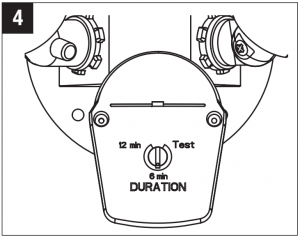
- Rotate the knob on bottom of the sensor to “Test” (Fig. 4).
- Turn on fixture at wall switch. Allow fixture to warm up approximately 1 minute before testing. (Light will come on and stay on during warm-up period.)
- Readjust sensor head up, down, left, or right until desired detection area is achieved.
NOTE: Make sure you stand motionless while you wait for the lights to turn off; otherwise the motion sensor will keep the light fixture on. - Once the light fixture goes off, move the time adjustment controls to the desired length of time.
The floodlight will remain on after the last motion is detected (5 seconds to 12 minutes) (Fig. 4).

SELECTING YOUR DESIRED FEATURE
| Mode of Operation | MODE Knob Adjustment | How to Set Power Switch |
| “Auto” Setting (motion activated) Lights should turn ON with motion only at night and on according to the time level selected by the time adjustment knob. |
5 seconds to 12 minutes | Keep the power to the fixture ON. |
| Standard Floodlight Setting Lights should stay ON continuously both day and night. (Can be reset manually or will automatically reset after 6 hours.) |
(Any position) | Turn power OFF and ON twice by wall switch within 2 seconds to set back to Manual Override Mode. Turn OFF for 10 seconds to reset to Auto Mode. |
| Test Setting Lights should turn ON with motion both day and night. Lights should turn OFF after 4 seconds. |
TEST (Both knobs at “T”) |
Keep the power to the fixture ON. |
TROUBLESHOOTING
| Problem | Cause / Solution |
| Light does not come ON with motion at night. | No power to the fixture.
Bulb is faulty.
Surrounding external ambient light is too bright. (If so, the unit may think it is daytime.)
TURN OFF POWER BEFORE CONTINUING
|
| Light comes ON for no apparent reason at night. | There is motion in the detection zone.
TEST FOR YOURSELF.
|
| Light stays ON at night and does not turn OFF. | There is motion in the detection zone.
|
| Light continuously blinks ON and OFF at night. | The light given from the unit’s own lamp is affecting the photo eye in sensor. (Light could be reflecting off of nearby surface.)
|
| Light is ON during the day. | The switch on the bottom of the motion sensor is in the test (“T”) mode.
|
| Cannot activate standard floodlight setting (Override). | Surrounding external ambient light is too bright. (If so, the unit may think it is daytime.)
Not enough time is allowed to enter the dusk to dawn mode.
|
2-YEAR LIMITED WARRANTY
THE FOLLOWING WARRANTY IS EXCLUSIVE AND IN LIEU OF ALL OTHER WARRANTIES, WHETHER EXPRESS, IMPLIED OR STATUTORY INCLUDING, BUT NOT LIMITED TO, ANY WARRANTY OF MERCHANTABILITY OR FITNESS FOR ANY PARTICULAR PURPOSE.
Cooper Lighting Solutions warrants to customers that, for a period of two years from the date of purchase, Cooper Lighting Solutions products will be free from defects in materials and workmanship. The obligation of Cooper Lighting Solutions under this warranty is expressly limited to the provision of replacement products. This warranty is extended only to the original purchaser of the product. A purchaser’s receipt or other proof of date of original purchase acceptable to Cooper Lighting Solutions. This is required before warranty performance shall be rendered. This warranty does not apply to Cooper Lighting Solutions products that have been altered or repaired that have been subjected to neglect, abuse, misuse or accident (including shipping damages). This warranty does not apply to products not manufactured by Cooper Lighting Solutions which have been supplied, installed, and/or used in conjunction with Cooper Lighting Solutions products. Damage to the product caused by replacement bulbs or corrosion or discoloration of brass components are not covered by this warranty.
LIMITATION OF LIABILITY:
IN NO EVENT SHALL COOPER LIGHTING SOLUTIONS BE LIABLE FOR SPECIAL, INDIRECT, INCIDENTAL, OR CONSEQUENTIAL DAMAGES (REGARDLESS OF THE FORM OF ACTION, WHETHER IN CONTRACT, STRICT LIABILITY, OR IN TORT INCLUD-ING NEGLIGENCE), NOR FOR LOST PROFITS; NOR SHALL THE LIABILITY OF COOPER LIGHTING SOLUTIONS FOR ANY CLAIMS OR DAMAGE ARISING OUT OF OR CONNECTED WITH THESE TERMS OR THE MANUFACTURE, SALE, DELIVERY, USE, MAINTENANCE, REPAIR OR MODIFICATION OF COOPER LIGHTING SOLUTIONS PRODUCTS, OR SUPPLY OF ANY REPLACEMENT PARTS THEREFORE, EXCEED THE PURCHASE PRICE OF COOPER LIGHTING SOLUTIONS PRODUCTS GIVING RISE TO A CLAIM. NO LABOR CHARGES WILL BE ACCEPTED TO REMOVE OR INSTALL FIXTURES.
To obtain warranty service, please contact Cooper Lighting Solutions, at 1-800 334-6871, press option 2 for Customer Service, or via e-mail [email protected] and include the following information:
- Name, address and telephone number
- Date and place of purchase
- Catalog and quantity purchase
- Detailed description of problem
All returned products must be accompanied by a Return Goods Authorization Number issued by the Company and must be returned freight prepaid. Any product received without a Return Goods Authorization Number from the Company will be refused. Cooper Lighting Solutions is not responsible for merchandise damaged in transit. Repaired or replaced products shall be subject to the terms of this warranty and are inspected when packed. Evident or concealed damage that is made in transit should be reported at once to the carrier making the delivery and a claim filed with them.
Reproductions of this document without prior written approval of Cooper Lighting Solutions are strictly prohibited.
For assistance, call 1-800-334-6871 or e-mail us at [email protected]
Cooper Lighting Solutions
1121 Highway 74 South, Peachtree City, GA 30269
P:770-486-4800
www.cooperlighting.com
© 2020 Cooper Lighting Solutions