
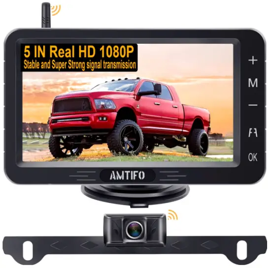
AMTIFO A6 Digital Wireless Backup Camera and Monitor Kit Instruction Manual
Useful accessories
Thank you for buying our camera. In return for your purchase, we would like to offer you a useful accessory.
Certificate
This system was certified by: CE & FCC & EMC & RoHs & Waterproof

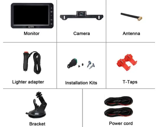
Package Includes
- Wireless License Plate Camera
- 5 inch Monitor
- Power Cords (2)
- Bracket
- Cigarette lighter adapter
- T-Taps (2)
- Split connector adapter
- Antenna
- Screws
- Instruction manual
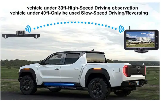
Working Range
This system is designed mainly for cars, trucks, campers, SUVs, vans, and minivans.
Vehicles under 33FT—High-Speed Driving Observation
Vehicles under 40FT—Slow-Speed Driving or Reversing
If your vehicle is too large or you encounter signal issues, please contact us immediately and we will provide a solution.
Before installing, read the information below
Please note the acceptable power supply voltage input to the monitor and camera.
Monitor: Voltage range 9V-35V
Camera: Voltage range 9V-24V
Note:
- If the power supply exceeds 24V it will cause the damage to the camera. We recommend DC 12V to the monitor and camera.
- If the positive and negative poles are reversed, the camera will be burnt out
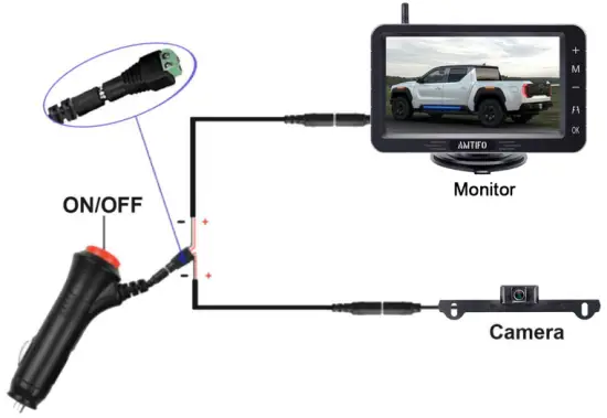
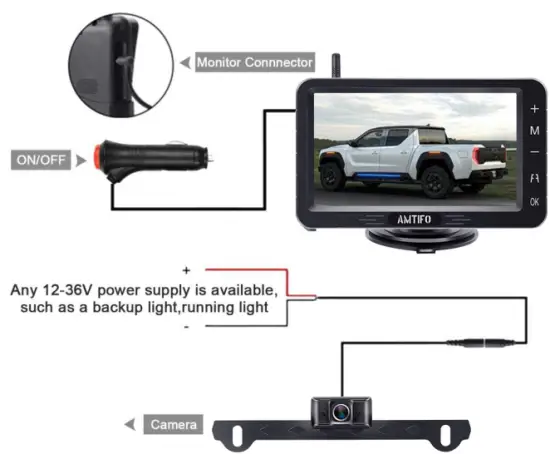
Before installation, you must test the device. Please reference the image below.
A. Plug power cords to the monitor and connect the power wires to camera (red-red, black-black).
B. Loosen the screws on green adapter, then insert the red wire (copper wire) to the Positive(+) slot, and the black wire(copper wire) to the Negative(-) slot.
C. Plug in the cigarette lighter and turn on the red switch. If you see an image on monitor, it means that the display is functioning properly.
Tips:
Test to make sure that your surroundings appear/display on the monitor screen! Once you have confirmed the monitor works, you are ready to install it.
If there is no image after you have installed the unit, check your connections to the power source. PLEASE NOTE: if you reverse the positive wire and negative wire, it will damage the camera so be cautious. If you cannot verify which wire is positive, connect the white wire to “ground” it (attach it to a metal part on vehicle) and then test the positive wire. Grounding it will protect the camera.
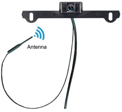
Attach waterproof antenna
Identify the thin wire that connects to the camera (see below sample image). This is the waterproof antenna. Since it is waterproof, you can affix the antenna to the inside or outside of the vehicle and it will not be affected by water or rain. We recommend attaching it near the license plate. If your vehicle is quite long, the signal may not be powerfully enough to reach the monitor so you may have to position it closer for better transmission.
Wires connection
Please pay attention to the positive and negative poles of the wire. If the positive and negative poles are reversed, it may surge and cause the monitor to smoke. If the monitor is emitting smoke, please turn off the power immediately and contact customer support.
- The monitor can be powered by a cigarette lighter.
- The camera can be powered by one of two methods.
a) If you plan to use the camera only when backing up, power it by attaching it to the backup/reverse tail-light of your car.
b) If you plan to use the camera continuously (while driving and reversing), power it by connecting it to the running light/tail-light (the lights that is on continuously while driving).
If you have questions about this step or the power supplies in your specific car make/model, email us.
- We have also provided an additional power cord that can be connected to the ACC/Fuse/Radio etc. to power the monitor
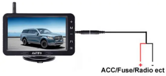
Tips: Red wire to positive pole, black wire to ground.
Note
- If you supply power to the cigarette lighter, please turn off the power through the red button of the plug when you are not use the system. Failure to do so will cause the monitor to drain the battery on the vehicle.
- If there is no image after your installing, please check the connections of power source. Or if you reversed the positive wire and negative wire, caused the no image. Please be cautious. If you cannot verify which wire is positive, you can connect the white/Black wire to ground (metal part on vehicle), then to test and connect the red wire to one of the back up light wire, if there is image appear on screen, it means you did correctly.
- In the light wires of most cars in the US, the red and black wire do not represent the positive and negative poles. Many times the black wire of the car lights is the positive pole, and the green or white wire is the negative pole. please check it before installation. If the wrong wire is connected and there is no image when connected, it means that the positive and negative poles are connected reversely. Need to unplug the power immediately and reconnect correctly. Otherwise it will burn the camera.
Installation Video and Signal Repairing
See the following link to watch an installation instruction video on
YouTube: https://youtu.be/NJDAwiPhteI
If the code doesn’t work, you can search the video ID on YouTube:
NJDAwiPhteI or Video name: AMTIFO A6 Wireless Rear View Camera System Operation Video on www.youtube.com or email us for help with the link.
Signal Pairing
The system signals between the camera and the monitor arrive already paired. If the signal is good, do not not attempt to pair it again yourself. If you lose signals or if you change the camera and the signal needs to be re-paired, read the below.
Pairing Steps:
Step 1 : Make sure the camera and monitor are powered on.
Step 2 : Touch the “Menu” button of the monitor into menu mode until “Pair” appears on the monitor, then press the ”+” button to pair the signal .
Step 3 : Wait for the image appearing .
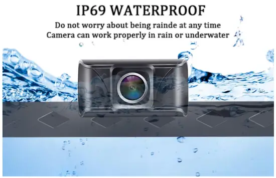
The camera is made of waterproof material IP69 Waterproof
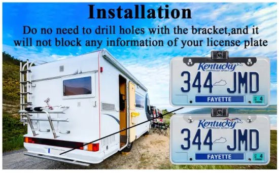
Camera Installation
The bracket of the camera is designed to attach to the license plate front or hide behind it on the back.
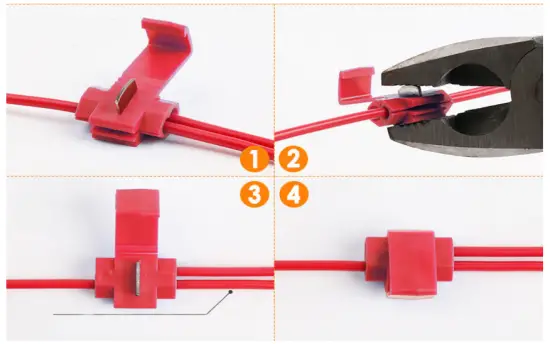
We have included T-Taps adapters to better protect the cord of the reversing back-up light or tail light. Reference the picture below for easier installation.
Step 1 : Plug the power cord of the reversing lamp line (back-up light cable) into the first hole of the clamp.
Step 2 : Put the backing auxiliary wire into the second hole of the clamp (the hole is blocked to prevent the wire pushing/leaking through)
Step 3 : Clamp the adapter, and clamp the iron sheet to the bottom.
Step 4 :It’s done!
(Note: The color of T-Taps may differ from the below image)
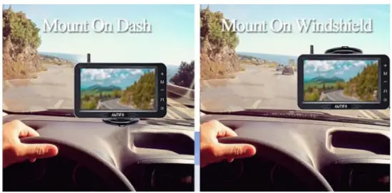
5 Inch Monitor Details and Installation
The monitor can attach to the dash or windshield (depending on your preference).
The button of the Monitor
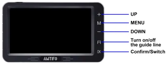
 Up (+): Touch to increase
 Menu : Touch this to enter the menu mode ( To enter the menu page, you must switch to a single screen)
 Down (-) : Touch to reduce
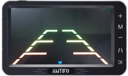
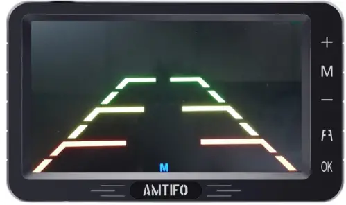
 : Guide Lines: The default guide line is on. Touch it turn on /off guide lines and DIY guide lines. You can adjust the height and width of guide line, and move the guide line left and right.
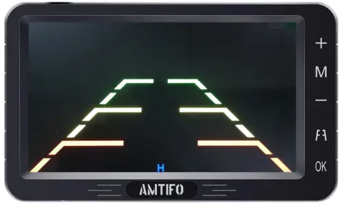
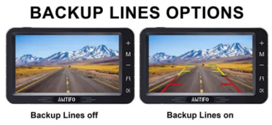
 Guide Lines ON/OFF:
 Confirm Key and switch channels quickly.
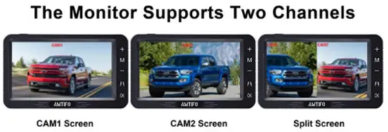
Single/Split Screen: The default is CAM1. Press the + key once to switch to CAM2, and press the + key twice switch to the split screen.
Product function introduction:
When you press the Menu button, you will enter the Menu mode and see 4 icon with functions:
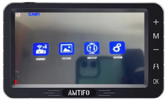
Note
- Touch + or – key can switch function icon
- Touch OK key for enter or confirm change
- Touch the menu button to exit the current function or menu )
Signal Pairing ( All items was paired before shipping. Just need pair signal when the camera lost signal or you changed new camera)
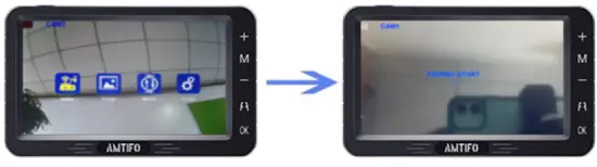
First icon Pairing :
Step 1 : Make sure the camera and monitor are powered .
Step 2 : When you choose Pairing, the icon is yellow, touch the OK button to enter pairing mode. The icon “Pairing Start” appear, Then Waiting for the image appearing . (About 20 seconds)
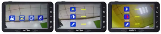
Second icon “Picture”
For setting brightness, contrast and saturation
When you choose 2nd icon “Picture” became yellow, Touch the “OK” button , you can see the brightness, contrast and saturation icon. and touch + or – button choose icon you want to adjust and press “OK” to choose it. When the selected icon turns red, you can touch + or-to adjust the data.
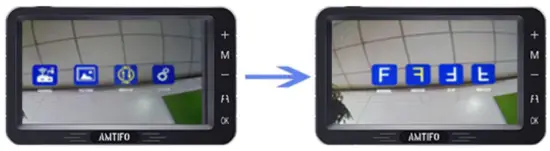
Third icon MIR-Flip:
When you choose 3rd icon MIR-Flip became yellow, touch the “OK” button to enter it. Then you can touch + or – to switch from mirror Rear View image, Normal front view image, vertical flip image. (4 options)
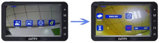
Setting:
Note: When you touch OK key enter this mode, Just touch + or – to switch different functions icon. Then touch OK key again to select it (became red icon) ,then you can touch + and – to adjust the data. After you done, touch M key quit current mode.
I. Switch Language
II. DELAYTIME ( This functions is useless )
III.SCANTIME (Set time for scan time for each camera channel)
IV. Automatic channel switching ON/OFF (If this function is ON, the CAM1 and CAM2 will switchable automatically, SCANTIME will set for scan time for each camera. You can set it for OFF ignore this functions.
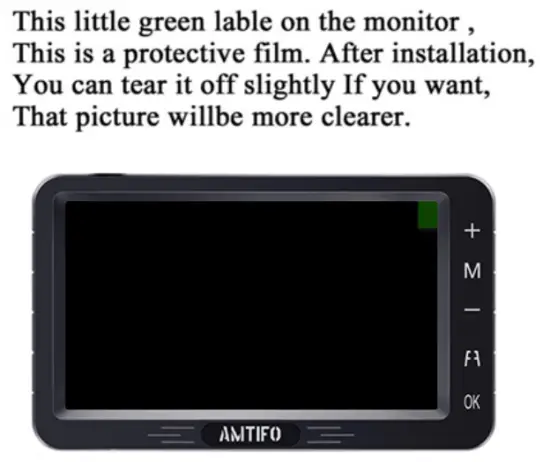
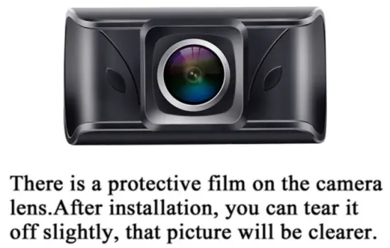
The protective film on the Camera and Monitor:
After you install the system, you can tear off the protective film if you would like to make the image clearer.
Warranty
Customer service
A Two Year Warranty and lifetime tech support is included with this product. (See customer service email at the front of page). Please contact us if you have ANY issues!

If any problems come up, please contact us for professional help and solutions!
Troubleshooting
- After installation, you turn on the monitor and camera power without images, at the same time, the monitor turns on for five seconds and then goes black, which means something wrong with the camera. You need to check that the camera is plugged in correctly. If the camera’s power cord is not connected correctly to the headlights, there is no images. Or you can touch the camera with your hand, if the camera gets hot, it’s powered on; if the camera surface temperature does not change, it is not connected to the power. Then, you need to reconnect to the power.
- If you find the image flashing all the time after you install this system. Please try to turn off the engine and keep the key in ACC, if the image does not flicker and the image starts to flicker after starting the engine, you need to add relay or filter to keep signal stable. ( BMW, Benz, VW’s cars will repel foreign devices and emit interfering currents. )
- If you connect the camera to the headlights and your headlights are LED, it will not work. Because the LED light cannot provide a constant direct current to the camera, you will need to switch to another power source to power the camera.
FCC Caution
This device complies with part 15 of the FCC Rules. Operation is subject to the following two conditions:
(1) This device may not cause harmful interference, and
(2) this device must accept any interference received, including interference that may cause undesired operation.
Any Changes or modifications not expressly approved by the party responsible for compliance could void the user’s authority to operate the equipment.
Note: This equipment has been tested and found to comply with the limits for a Class B digital device, pursuant to part 15 of the FCC Rules. These limits are designed to provide reasonable protection against harmful interference in a residential installation. This equipment generates uses and can radiate radio frequency energy and, if not installed and used in accordance with the instructions, may cause harmful interference to radio communications. However, there is no guarantee that interference will not occur in a particular installation. If this equipment does cause harmful interference to radio or television reception, which can be determined by turning the equipment off and on, the user is encouraged to try to correct the interference by one or more of the following measures:
- Reorient or relocate the receiving antenna.
- Increase the separation between the equipment and receiver.
- Connect the equipment into an outlet on a circuit different from that to which the receiver is connected.
- Consult the dealer or an experienced radio/TV technician for help.
This equipment complies with FCC radiation exposure limits set forth for an uncontrolled environment.