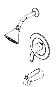

TUB AND SHOWER FAUCET WITH TWO
HANDLE OPTIONS
10TS1-BN-AV – Brushed nickel finish

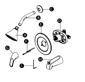
PACKAGE AND HARDWARE CONTENTS
| PART | DESCRIPTION | QUANTITY |
| A | Shower head | 1 |
| B | Shower arm | 1 |
| C | Shower arm flange | 1 |
| D | Valve body | 1 |
| E | Eschutcheon | 1 |
| F | Screws | 2 |
| G | Lever handle | 1 |
| H | Tub spout with diverter | 1 |
| I | Hex wrench | 1 |

Please read and understand this entire manual before attempting to assemble, operate or install the product.
WARNING
- Protect your eyes with safety glasses when cutting or soldering water
supply lines.
CAUTION
- If you solder the joints during installation, the seats, cartridges, and washers
must be removed before using a flame or the warranty will be voided on
these parts. - Cover the drain to avoid losing parts.
PREPARATION
Before beginning the assembly of the product, make sure all parts are present. Compare parts with the package and hardware contents list. If any part is missing or damaged, do not attempt to assemble the product. Contact customer service for replacement parts.
Estimated Assembly Time: 30 minutes
Tools required for assembly (not included): adjustable wrench, thread sealant tape, strap wrench, Phillips head screwdriver, silicone installation may vary depending on how the previous tub and/or shower faucets were installed. Supplies necessary for the installation of the product are not all included; however, they are available wherever plumbing supplies are sold. Prior to beginning installation, turn off the hot and cold water lines, then turn on the old faucet to release built-up pressure. When installing the new tub and/or shower faucets, hand tighten the connector nuts. DO NOT OVERTIGHTEN. Connections that are too tight will reduce the integrity of the system.
Need Help? Please call our toll-free line at (877) 319-3757 (7:30 am to 4:30 pm CST) for additional assistance or service.
Homewerks Worldwide, LLC • Lake Bluff, IL 60044 • HomewerksWW.com
PRODUCT SPECIFICATIONS
| Showerhead Max. Flow Rate: 1.8 GPM (6.8 LPM) at 80 PSI |
| ASME A112.18.1/CSA B125 |
| Brushed nickel finish |
| Washerless cartridges |
ASSEMBLY INSTRUCTIONS
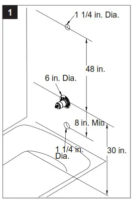
- Shut off water supply to the tub and shower. Verify that the hole sizes and position of the holes in the wall are correct.
IMPORTANT: Complete valve replacement is required for this tub/ shower unit. An access hole must be cut with enough room to install the new tub/ shower valves inside the wall. Professional installation is recommended.
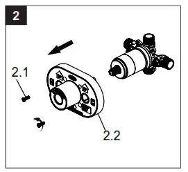
CAUTION: Do not use PEX tubing for pipe from the valve to the tub spout.  Unscrew the screws (2.1), and remove the plaster guard (2.2).
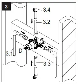
- Tub and shower outlet connections: Wrap thread sealant tape around the pipe threads in a clockwise direction as shown. Connect the hot and cold water supply lines (3.1) (not included), the shower (3.2) (not included), and the tub outlet pipes (3.3) (not included) to the valve body (D). Connect the pipe elbows (4.4) (not included) to the ends of both pipes, and tighten with a wrench.
NOTE: Be sure to position the valve body (D) correctly in the wall, with the markings “UP” facing upward. The hot water supply lines go into the H inlet, and the cold water supply lines go into the C inlet. DO NOT USE PEX or CPVC between the valve and spout.
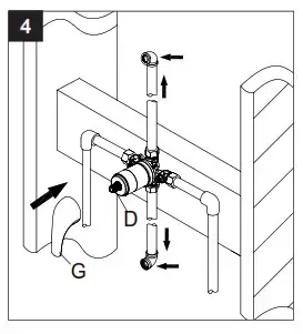
- Flushing water lines:Turn on the water. Place the handle (G) on the valve body inverter (D) and turn the handle (G) to the full on mixed position. Turn on the hot and cold water supply lines and allow the water
to flow from the outlets for one minute, or until all foreign debris has been flushed out. Check for leaks. Shut
off the water at the faucet and supply lines. Remove the handle (G).
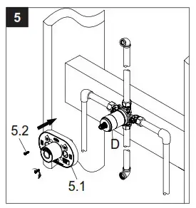
- Place the plaster guard (5.1) onto the valve body (D) and secure the screws (5.2).
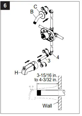
- Shower arm, flange and tub spout installation: Insert the long end of the shower arm (B) through the flange (C), then wrap thread sealant tape aroung the long end of the shower arm (B) in a clockwise direction. Install the long end of the shower arm (B) into the pipe elbow inside the wall. Tighten the shower arm (B), but do not overtighten. Wrap thread sealant tape around the pipe threads of the tub spout outlet (6.3) (not included). Connect the tub spout outlet pipe (the tub spout outlet pipe should project out 3-15/16 in. to
4-3/32 in. from the finished wall to the lower pipe elbow (6.4) (not included). Thread the tub spout (H) onto the threaded connection in a clockwise direction until the tub spout (H) becomes flush with the finished wall. Use a wrench to tighten the tub spout (H).
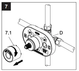
- Before installing the escutcheon (E), remove the plastic cap (7. 1) from the valve body (D) by twisting the cap (7. 1in a clockwise direction.
- Checking for leaks: Turn on the water. Place the handle (G) on the valve body inverter (D) and turn the handle (G) to the full-on mixed position. When the valve is turned on, water normally flows through the tub spout (H). To activate the shower, turn the valve on and pull the tub spout knob (8.1) up. Hold the tub spout knob (8.1) until the water flows continuously from the shower arm (B). Check for leaks. Shut off the water at the faucet and supply lines. Remove the handle (G).
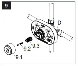
- Adjusting the Temperature: Unscrew the sleeve (9.1) from the valve body (D). Unscrew the screw (9.2) and remove the inverter (9.3) from the valve body (D).
NOTE: If you do not wish to adjust the amount of hot water that is allowed through the valve, proceed to st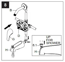
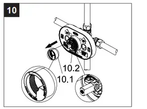
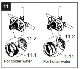
- Please note the position of the red limit stop ring (10.1) on the cartridge assembly (10.2). Remove the red limit stop ring (10.1) from the cartridge assembly.
- Adjusting maximum temperature: For colder water, adjust the red limit stop ring (11.1) in a clockwise direction and reinstall the red limit stop ring (11.1) onto the cartridge assembly (11.2). For hotter water, adjust the red limit stop ring (11.1) in a counterclockwise direction and reinstall the red limit stop ring (11.1)
onto the cartridge assembly (11.2).
NOTE: A thermometer (not included) can be held in the water stream to aid in reaching the desired water temperature.
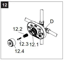
- NOTE: Rotate the cartridge stem (12.1) clockwise to turn off the water before installing the handle. Place the inverter (12.2) onto the valve body (D) and secure with the screw (12.3). Screw the sleeve (12.4onto the valve body handle (D).
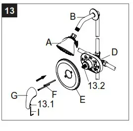
- Lever handle and showerhead installation: Install the escutcheon (E) onto the valve body (2) using the escutcheon screws (F). Place the lever handle (G) onto the inverter (13.2) and tighten the set screw (13.1) with the provided hex wrench (I). Attach the showerhead (A) onto the shower arm (B). Hand tightens.
OPERATING INSTRUCTIONS
The handles control the flow of hot and cold water to the faucet. Turn the right handle for cold water. Turn the left handle for hot water. Rotating the handles opens the cartridges and causes water to flow from the spout. The degree of handle rotation determines the volume of water flow. Returning the handles to the original position stops the flow of water.
CARE AND MAINTENANCE
Clean periodically with a soft cloth. Avoid abrasive cleaners, steel wool, and harsh chemicals as these will dull the finish and void your warranty.
TROUBLESHOOTING
| PROBLEM | POSSIBLE CAUSE | SOLUTION |
| Leaks from the spout | Damaged or dirty valve seat. | Remove faucet handle, cartridge, housing and valve spool to check the rubber valve seal. Clean it or replace by calling Customer Service. |
| Leaks from underneath the handle |
Bonnet is loose or bottom gasket on cartridge is dirty or twisted. |
Remove the faucet handle. Tighten the bonnet. Clean or replace the O-ring. |
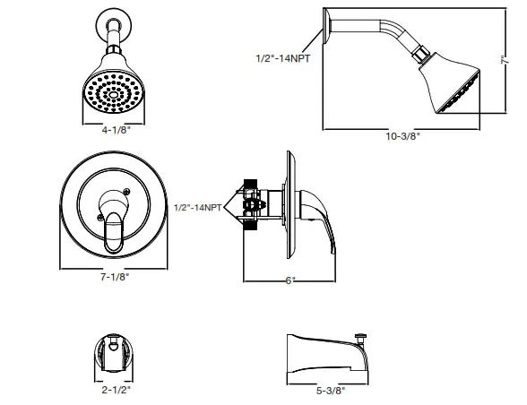
ROUGH-IN
REPLACEMENT PARTS
For replacement parts, call our customer service department at (877) 319-3757, 7:30 a.m. – 4:30 p.m., CST, Monday – Friday.
| PART | DESCRIPTION | PART # |
| I | Lever handle assembly | RP13581BN |
| 2 | Screw | RP50208 |
| 3 | Eschutcheon assembly | RP80040BN |
| 4 | Screw | RP50066 |
| 5 | Inverter | RP70328 |
| 6 | Sleeve | RP80297BN |
| 7 | 0-ring | RP60091 |
| 8 | Bonnet | RP70327BN |
| 9 | Cartridge | RP22019 |
| 10 | 0-ring | RP60101 |
| 1 I | Shower arm flange | RP38026BN |
| 12 | Shower arm | RP38027BN |
| 13 | Showerhead | RP38365BN |
| 14 | Tub spout with diverter | RP33019BN |
| 15 | Acrylic handle assembly | RP13582 |
LIMITED LIFETIME WARRANTY
The distributor warrants to the original consumer purchaser this product to be free from defects in material and workmanship under normal use in residential applications. At its option, the Company will provide repair parts or replace the defective product when the product is used in accordance with the manufacturer’s specifications. Use of mild abrasive, abrasive or chemical cleaners may damage the finish of the faucet. We recommend cleaning your faucet with a soft cloth, moistened with water. Damage resulting from the use of abrasive or chemical cleaners SHALL VOID THIS WARRANTY. This warranty is not applicable to any products or parts of products where damage is caused by use of non-genuine parts; is due to installation error, product misuse, negligence or faulty maintenance; or where the product is not installed according to local building codes. This warranty excludes labor charges or damage incurred during installation, repair or replacement, and any indirect, incidental or consequential damages, losses, injury or costs of any nature. This warranty is in lieu of and excludes all other warranties, conditions and guarantees, whether expressed or implied, including without restriction those of merchantability or fitness of use. Liability under this warranty will not exceed the purchase price for the product claimed to be defective by the original consumer purchaser. Some states or provinces do not allow the exclusion or limitation of consequential damages so the above limitations or exclusions may not apply. This warranty gives you specific legal rights and you may also have other rights which vary from state to state, or province to province. Inquiries regarding warranty claims can be directed to (877) 319-3757, 7:30 a.m. – 4:30 p.m., CST, Monday – Friday.