
Package Contents
- 1 2/4-Port USB 2.0 Peripheral Switch (US221A/US421A)
- 1 1.8 m USB Type A to USB Type B Cable
- 1 User Instructions
Hardware Review (Top View)


Hardware Review (Rear View)

Hardware Installation
Support and Documentation Notice
All information, documentation, firmware, software utilities, and specifications contained in this package are subject to change without prior notification by the manufacturer.To reduce the environmental impact of our products, ATEN documentation and software can be found online at :http://www.aten.com/download/
Technical Support
Scan for Software Downloads and more information
- ATEN Website
- User Manual
EMC Information
FEDERAL COMMUNICATIONS COMMISSION INTERFERENCE STATEMENT: This equipment has been tested and found to comply with the limits for a Class B digital service, pursuant to Part 15 of the FCC rules. These limits are designed to provide reasonable protection against harmful interference in a residential installation. Any changes or modifications made to this equipment may void the user s authority to operate this equipment. This equipment generates, uses, and can radiate radio frequency energy. If not installed and used in accordance with the instructions, may cause harmful interference to radio communications. However, there is no guarantee that interference will not occur in a particular installation. If this equipment does cause harmful interference to radio or television reception, which can be determined by turning the equipment off and on, the user is encouraged to try to correct the interference by one or more of the following measures:
- Reorient or relocate the receiving antenna;
- Increase the separation between the equipment and receiver;
- Connect the equipment into an outlet on a circuit different from that to which the receiver is connected;
- Consult the dealer/an experienced radio/television technician for help.
FCC Caution: Any changes or modifications not expressly approved by the party responsible for compliance could void the user’s authority to operate this equipment.
This device complies with Part 15 of the FCC Rules. Operation is subject to the following two conditions:
- this device may not cause harmful interference, and
- this device must accept any interference received, including interference that may cause undesired operation.
Important : Before proceeding, download the Installation and Operation Manual by visiting the website, www.aten.com and navigating to the product page. The manual includes important warnings, loading specifications and grounding instructions.
Requirements
- Computers : USB host controller
- Cables : USB to USB cables to connect the computers to the peripheral device.
Note: Only one USB Type A to USB Type B cable is provided in the US221A / US421A package. You will need to purchase an additional USB Type A to USB Type B cables for each computer you wish to connect to theUS221A / US421A.
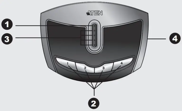
Hardware Review
- Top View
- Lock LED
- Port Selection Pushbutton(s)
- Port Selected LEDs
- Beeper On/Off Switch (on side)
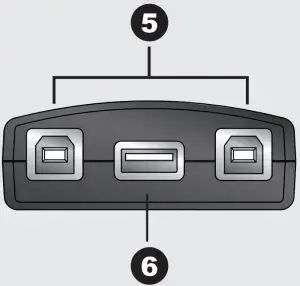
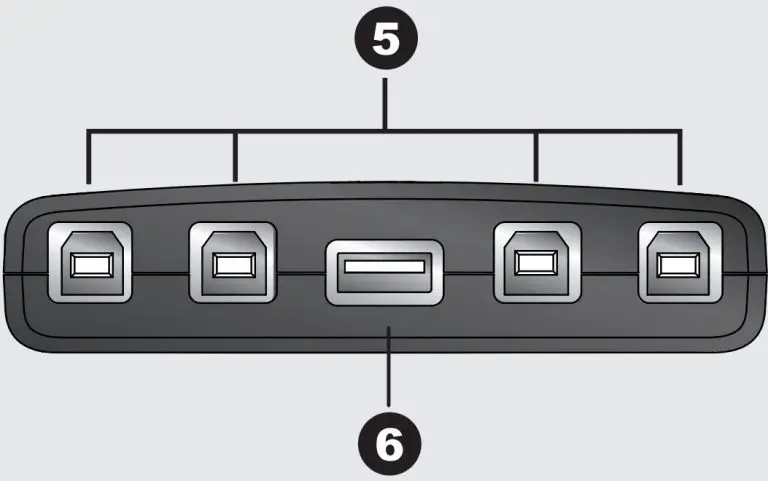
- Rear View
- USB Type B Computer Port
- USB Type A Peripheral Port
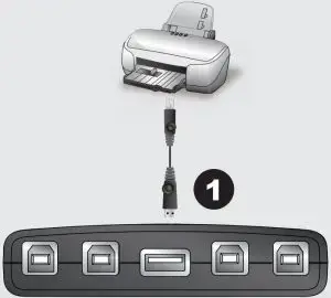
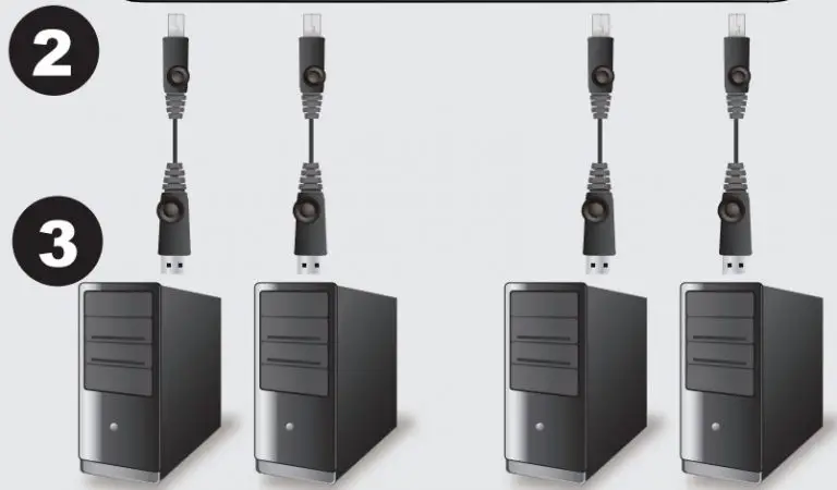
- Hardware Installation : To install the US221A / US421A, do the following:
- Use your USB device’s USB cable to connect it to the US221A / US421A’s USB Type A port.
- Plug the USB Type B connector of the USB Type A to USB Type B cable provided with the US221A / US421A package into any available port on the US221A / US421A.
- Plug the Type A connector into the computer’s USB host port. Repeat steps 2 and 3 for any other computers you are installing.
Manual Operation
US221A : To toggle the USB peripheral focus between the two computers, press the port selection pushbutton (located on the top of the unit) The selected port LED will flash and the unit will beep. When the flashing stops and the LED becomes steady (in about four seconds), that port has the peripheral focus.
US421A : To switch the peripheral focus to another port, press the push button that corresponds to that port. The selected port LED will flash and the unit will beep. When the flashing stops and the LED becomes steady (in about four seconds), that port has the peripheral focus.
Lock/Unlock Peripheral Focus
To lock the peripheral focus on a certain computer, press and hold the push button that corresponds to that port for two seconds, or until the orange LED lights up. To unlock the peripheral focus, press and hold the pushbutton that corresponds to that port for one second, or until the orange LED turns off.
Software Operation
The US221A / US421A has a software-based configuration utility that can be used to configure the US221A / US421A’s settings, such as the Auto Switch function, Manual Switch and Release reminder, and sound effects. The utility can also be used to lock and unlock control of the US221A/US421A.
Note: Windows users should login as an administrator to install and launch the US221A/US421A software.
]]>CS22DP
2-Port USB DisplayPort Cable KVM Switch
Quick Start Guide
Package Contents
- CS22DP 2-Port USB DisplayPort Cable KVM Switch
- User Instructions
Hardware Review

Hardware Installation
![]() To prevent damage to your installation from power surges or static electricity, it is important that all connected devices are properly grounded.
To prevent damage to your installation from power surges or static electricity, it is important that all connected devices are properly grounded.
Support and Documentation Notice
All information, documentation, firmware, software utilities, and specifications contained in this package are subject to change without prior notification bythe manufacturer. To reduce the environmental impact of our products, ATEN documentation and software can be found online at http://www.aten.com/download/
Technical Support www.aten.com/support
Scan for more information

http://www.aten.com/products/productItem.php?model_no=CS22DP
EMC Information
FEDERAL COMMUNICATIONS COMMISSION INTERFERENCE
STATEMENT:
This equipment has been tested and found to comply with the limits for a Class B digital service, pursuant to Part 15 of the FCC rules. These limits are designed to provide reasonable protection against harmful interference in a residential installation. Any changes or modifications made to this equipment may void the user s authority to operate this equipment. This equipment generates, uses, and can radiate radio frequency energy. If not installed and used in accordance with the instructions, may cause harmful interference to radio communications. However, there is no guarantee that interference will not occur in a particular installation. If this equipment does cause harmful interference to radio or television reception, which can be determined by turning the equipment off and on, the user is encouraged to try to correct the interference by one or more of the following measures:
– Reorient or relocate the receiving antenna;
– Increase the separation between the equipment and receiver;
– Connect the equipment into an outlet on a circuit different from that to which the receiver is connected;
– Consult the dealer/an experienced radio/television technician for help.
FCC Caution:
Any changes or modifications not expressly approved by the party responsible for compliance could void the user’s authority to operate this equipment.
This device complies with Part 15 of the FCC Rules. Operation is subject to the following two conditions:(1) this device mat not cause harmful interference, and(2) this device must accept any interference received, including interference that may cause undesired operation.
CS22DP 2-Port USB DisplayPort Cable KVM Switch
Hardware Review
Hardware Installation
To set up the CS22DP, do the following:
- Plug the USB mouse, USB keyboard, monitor, microphone and speakers into their respective ports on the CS22DP.
Note: The USB ports can be used for USB peripheral sharing. To do so, plug the peripherals and the keyboard or mouse into a USB hub, then plug the hub into the keyboard or mouse port. - Plug the DisplayPort, USB and Audio connectors of the attached KVM cables into their respective ports on the computers you are installing.
- (Optional) If the power supply to the attached USB peripherals is not sufficient, plug a USB cable into the Micro USB power jack to get power from another USB power source (i.e. PC, USB hub, DC 5V USB power adapter).
Note: A USB to Micro USB cable is not included in this package. Contact your ATEN dealer for product information.
Operation
Use the Remote Port Selector pushbutton* to switch between the two computers.
Note*: Long press the remote port selector pushbutton for 3 seconds to enable/disable monitor re-detection mode on the selected PC port.
© Copyright 2019 ATEN® International Co., Ltd. ATEN and the ATEN logo are trademarks of ATEN International Co., Ltd. All rights reserved. All other trademarks are the property of their respective owners.
This product is RoHS compliant.
Part No. PAPE-1223-H62G

Printing Date: 04/2019

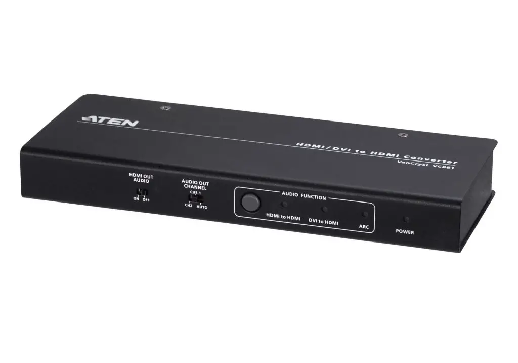
ATEN 4K HDMI DVI-D HDMI Converter Audio Embedder De-Embedder User Guide
Model: VC881
© Copyright 2018 ATEN® International Co., Ltd.
ATEN and the ATEN logo are trademarks of ATEN International Co., Ltd. All rights reserved.
All other trademarks are the property of their respective owners.
Part No. PAPE-1223- N30G Printing Date: 06/2018
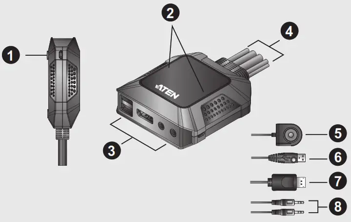
A. Hardware Review

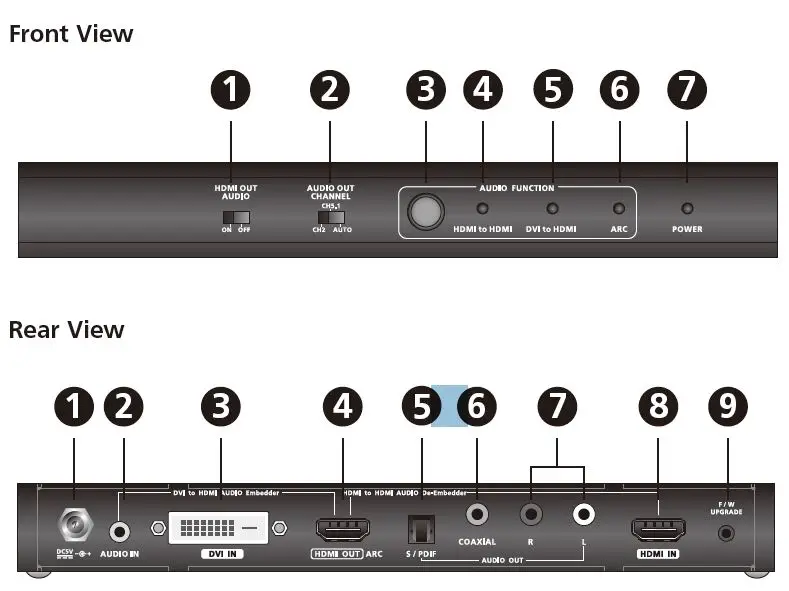
Front View
- HDMI Audio Out Switch
- Audio Out Channel Switch
- Audio Function Button
- HDMI to HDMI LED
- DVI to HDMI LED
- ARC LED
- Power LED
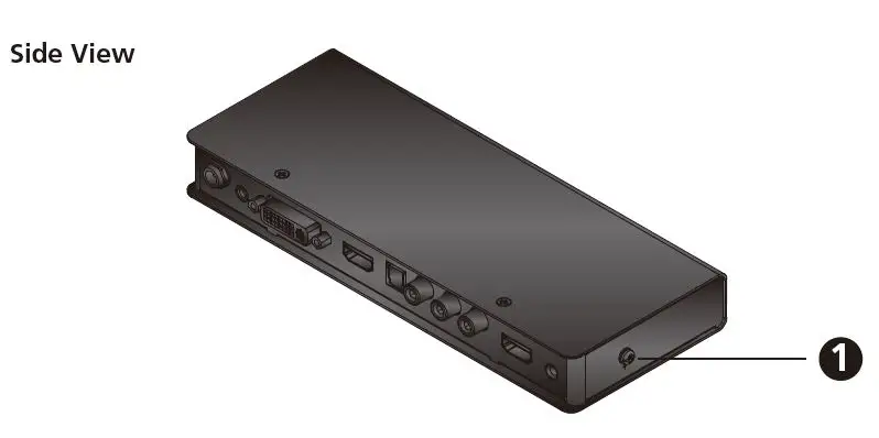
Side View
- Grounding Terminal
Rear View
- Power Jack
- Audio In
- DVI In
- HDMI Out
- Audio Out (S/PDIF)
- Audio Out (Coaxial)
- Audio Out (Stereo)
- HDMI In
- Firmware Upgrade Port
Package Contents
- 1 VC881 4K HDMI / DVI-D to HDMI Converter with Audio Embedder and De embedder
- 1 Power Adapter
- 1 User Instructions
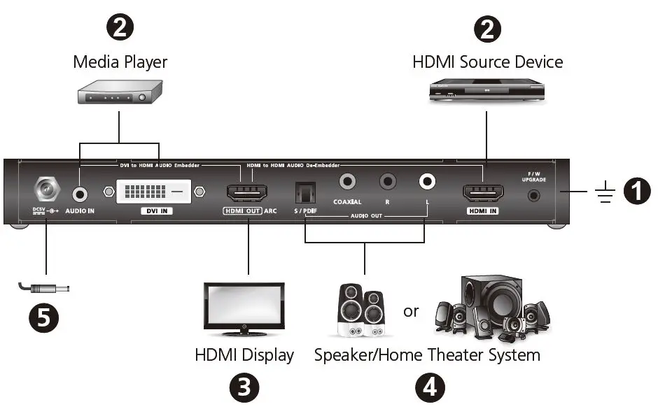
B Hardware Installation
Follow the steps below to safely install the VC881 unit.
- Ground the VC881 by connecting one end of a grounding wire to the grounding terminal, and the other end of the wire to a suitable grounded object.
Note: Do not omit this step. Proper grounding helps prevent damage to the unit from power surges or static electricity. - Connect an HDMI and/or DVI source device to the VC881.
• For an HDMI source device, use an HDMI cable to connect the source device’s HDMI
Out port to the VC881’s HDMI In port.
• For a DVI source device, use a DVI cable to connect the source device’s DVI Out port to the VC881’s DVI In port and use an audio cable to connect the source device’s Audio Out port to the VC881’s Audio In port. - Connect an HDMI display to the VC881 using an HDMI cable.
- (Optional) To use an independent speaker or a home theater system, use an appropriate audio cable to connect the VC881’s Audio Out port(s) to the speaker/ home theater system’s Audio In port(s).
- Plug in the supplied power adapter to the VC881’s Power Jack.
- Power on all equipment. The VC881’s power LED lights green.
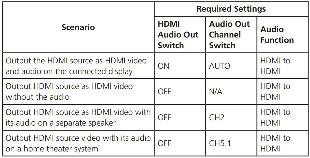
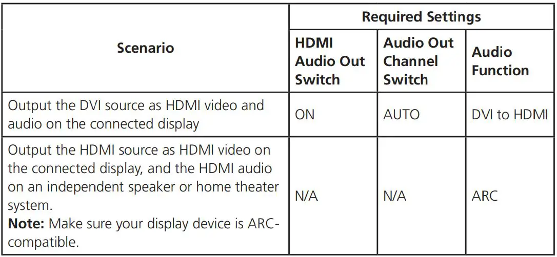
- Based on your setup scenario, adjust the VC881’s audio settings listed in the table:
Support and Documentation Notice
All information, documentation, firmware, software utilities, and specifications contained in this package are subject to change without prior notification by the manufacturer.
To reduce the environmental impact of our products, ATEN documentation and software can be found online at http://www.aten.com/download/
Technical Support
www.aten.com/support
Scan for more information
EMC Information
FEDERAL COMMUNICATIONS COMMISSION INTERFERENCE STATEMENT:
This equipment has been tested and found to comply with the limits for a Class A digital device, pursuant to Part 15 of the FCC Rules. These limits are designed to provide reasonable protection against harmful interference when the equipment is operated in a commercial environment. This equipment generates, uses, and can radiate radio frequency energy and, if not installed and used in accordance with the instruction manual, may cause harmful interference to radio communications. Operation of this equipment in a residential area is likely to cause harmful interference in which case the user will be required to correct the interference at his own expense.
FCC Caution: Any changes or modifi cations not expressly approved by the party responsible for compliance could void the user’s authority to operate this equipment.
Warning: Operation of this equipment in a residential environment could cause radio interference.
This device complies with Part 15 of the FCC Rules. Operation is subject to the following two conditions: (1) this device may not cause harmful interference, and (2) this device must accept any interference received, including interference that may cause undesired operation.
]]>ATEN 4-port USB 2.0 Cat 5 Extender
EMC Information
FEDERAL COMMUNICATIONS COMMISSION STATEMENT:
This equipment has been tested and found to comply with the limits for a Class B digital device, pursuant to Part 15 of the FCC Rules. These limits are designed to provide reasonable protection against harmful interference in a residential installation. This equipment generates, uses and can radiate radio frequency energy and, if not installed and used in accordance with the instructions, may cause harmful interference to radio communications.
However, there is no guarantee that interference will not occur in a particular installation. If this equipment does cause harmful interference to radio or television reception, which can be determined by turning the equipment off and on, the user is encouraged to try to correct the interference by one or more of the following measures:
- Reorient or relocate the receiving antenna.
- Increase the separation between the equipment and receiver.
- Connect the equipment into an outlet on a circuit different from that to which the receiver is connected.
- Consult the dealer or an experienced radio/television technician for help.
FCC Caution: Any changes or modifications not expressly approved by the party responsible for compliance could void the user’s authority to operate this equipment.
This device complies with Part 15 of the FCC Rules. Operation is subject to the following two conditions:
- This device may not cause harmful interference, and
- This device must accept any interference received, including interference that may cause undesired operation
Suggestions:
Shielded twisted pair (STP) cables must be used with the unit to ensure compliance with FCC & CE standards.
User Notice
All information, documentation, and specifications contained in this manual are subject to change without prior notification by the manufacturer. The manufacturer makes no representations or warranties, either expressed or implied, with respect to the contents hereof and specifically disclaims any warranties as to merchantability or fitness for any particular purpose. Any of the manufacturer’s software described in this manual is sold or licensed as is. Should the programs prove defective following their purchase, the buyer (and not the manufacturer, its distributor, or its dealer), assumes the entire cost of all necessary servicing, repair and any incidental or consequential damages resulting from any defect in the software.
The manufacturer of this system is not responsible for any radio and/or TV interference caused by unauthorized modifications to this device. It is the responsibility of the user to correct such interference.
The manufacturer is not responsible for any damage incurred in the operation of this system if the correct operational voltage setting was not selected prior to operation. PLEASE VERIFY THAT THE VOLTAGE SETTING IS CORRECT BEFORE USE.
Package Contents
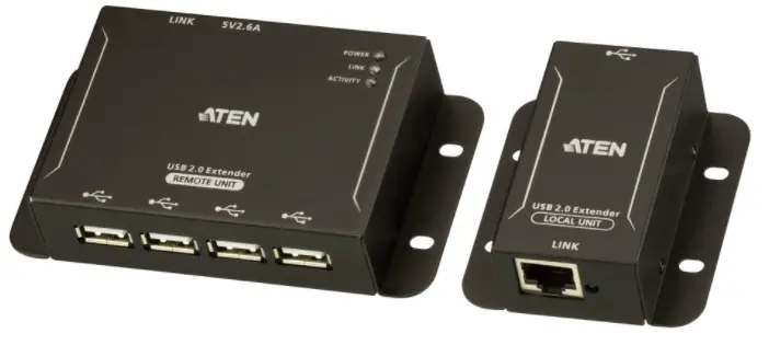
- 1 UCE3250L 4-port USB 2.0 Cat 5 Extender (local unit)
- 1 UCE3250R 4-port USB 2.0 Cat 5 Extender (remote unit)
- 1 USB Type-A Male to Type-B Male Cable
- 1 Power Adapter
- 1 User Instructions
Note: Make sure that all of the items are present and in good order. If anything is missing or was damaged in shipping, please contact your dealer for further assistance.
Introduction
Overview
The UCE3250 4-port USB 2.0 Cat 5 Extender is a two-unit device that serves as a USB hub and a USB extender. The UCE3250 unit can connect as many as 4 USB peripherals from up to 50 meters away from your computer over a Cat 5 / 5e / 6 Ethernet cable.
The UCE3250 transmits data through signal packages with better compatibility and preserves the integrity of the data over long distances. The power supply at the remote UCE3250 unit helps provide sufficient power to any type of USB device, such as flash drives, keyboards, mice, webcams, scanners, or printers, etc.
With its durable metal housing, this high-quality USB extender provides a fast and flexible solution for industrial applications. In addition, the compact size and integrated wall mounting enables space-saving installation.
Features
- High-Speed USB 2.0 compliant with a data transfer rate of up to 480 Mbps
- Extension distance of up to 50m over a Cat 5/5e/6 cable
- Receives up to 4 USB peripherals of all types – flash drives, keyboards, mice, webcams, scanners, printers and more
- Metal casing with wall mount design supports industrial deployment
- Supports Windows, OS X, and Linux
- Plug-and-play
Supported Operating System
The UCE3250 supports computers using the following operating systems.
| Operating System | Version | |
| Windows | Vista, XP, 7, 8, 8.1, 10 | |
| Linux | RedHat | 6.0 or higher |
| SuSE | 8.2 or higher | |
| Mac | OS 9 or higher | |
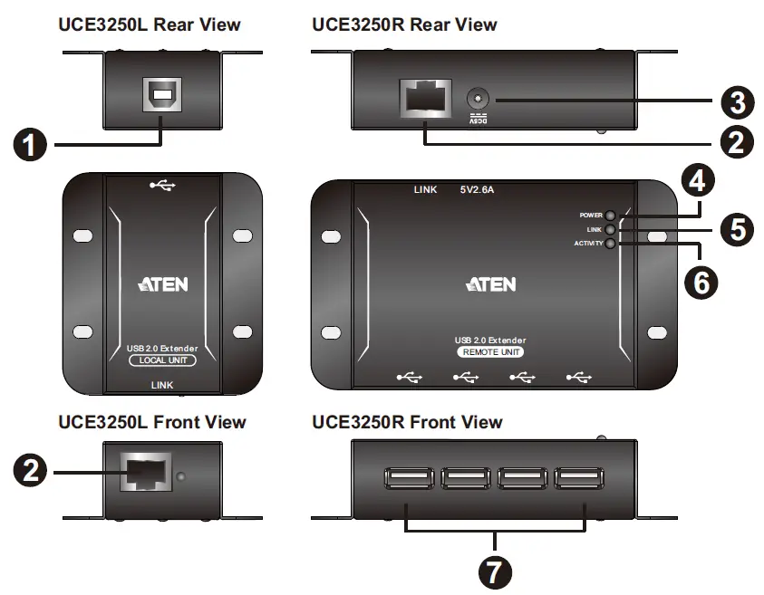
Hardware Components
| No. | Component | Description |
| 1 | USB Type-B Port | Receives a USB Type-A male to male cable that connects the UCE3250L to the computer in your setup. |
| 2 | Link Port | Receives a Cat 5/5e/6 cable that sends and transmits data between the UCE3250L and the UCE3250R. |
| 3 | Power Jack | Receives the power adapter. |
| 4 | Power LED | Lights red to indicate that the power is being supplied to the unit. |
| 5 | Link LED | Lights green to indicate that the USB connection between the UCE3250L and the UCE3250R is stable. |
| 6 | Activity LED | Flashes amber to indicate that data is being transmitted between the UCE3250L and UCE3250R. |
| 7 | USB Type-A Ports | Receive USB cables to connect to USB peripherals you wish to access from the computer in your setup. |
Hardware Setup
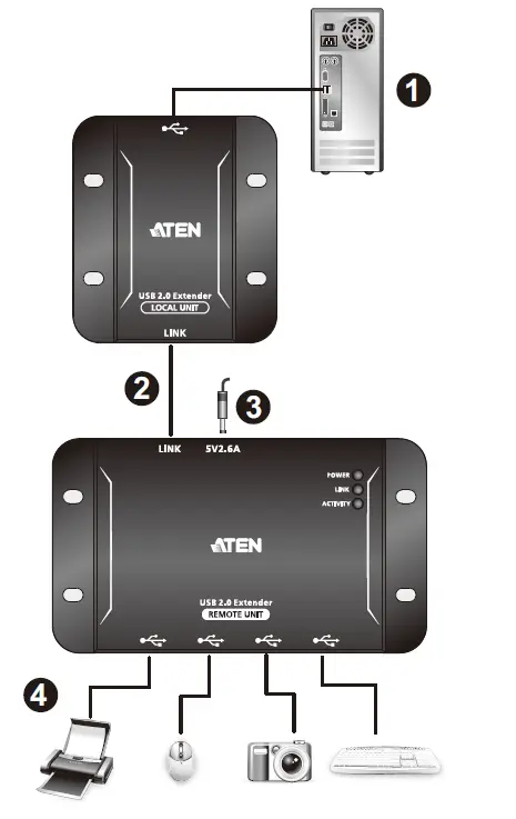
Installation
Follow the illustration and the steps below to safely install your UCE3250 unit.
- Connect the UCE3250L’s USB Type-B Port to a computer using the supplied USB Type-B Male to Type-A Male Cable.
- Connect the Link Ports of UCE3250L and UCE3250R with a Cat 5/5e/6 cable.
- Plug the supplied power adapter into an AC power source, and then plug the other end into the UCE3250R’s Power Jack.
- Use USB cables to connect up to 4 USB 2.0 peripheral devices to the UCE3250R’s USB Type-A Ports.
Wall Mount
The UCE3250 can also be mounted on the wall as illustrated below.
Technical Support
International
- For online technical support – including troubleshooting, documentation, and software updates: http://eservice.aten.com
- For telephone support, Telephone Support, page iii.
North America
| Email Support | [email protected] | |
| Online Technical Support | Troubleshooting Documentation Software Updates | http://www.aten-usa.com/support |
| Telephone Support | 1-888-999-ATEN ext 4988 | |
When you contact us, please have the following information ready beforehand:
- Product model number, serial number, and date of purchase.
- Your computer configuration, including operating system, revision level, expansion cards, and software.
- Any error messages displayed at the time the error occurred.
- The sequence of operations that led up to the error.
- Any other information you feel may be of help.
Specifications
| Function | UCE3250L | UCE3250R | |
| Connectors | USB Port | 1 x USB Type-B Female | 4 x USB Type-A Female |
| USB Link | 1 x RJ-45 Female | 1 x RJ-45 Female | |
| Power | N/A | 1 x DC Jack | |
| USB Specification | 2.0 / 1.1 High / Full / Low Speed | ||
| USB Devices Support | N/A | 4 USB devices | |
| Power Consumption | Bus-powered | Self-powered, DC 5V, 13W | |
| Environmental | Operating Temperature | 0–50°C | |
| Storage Temperature | -20–70°C | ||
| Humidity | -20% – 80% RH, Non-condensing | ||
| Physical Properties | Housing | Metal | |
| Weight | 0.09 kg | 0.16 kg | |
| Dimensions (L x W x H) | 6.70 x 6.02 x 2.37 cm | 6.33 x 11.04 x 2.41 cm | |
Limited Warranty
ATEN warrants its hardware in the country of purchase against flaws in materials and workmanship for a Warranty Period of two [2] years (warranty period may vary in certain regions/countries) commencing on the date of original purchase. This warranty period includes the LCD panel of ATEN LCD KVM switches. Select products are warranted for an additional year (see A+ Warranty for further details). Cables and accessories are not covered by the Standard Warranty.
What is covered by the Limited Hardware Warranty
ATEN will provide a repair service, without charge, during the Warranty Period.
If a product is detective, ATEN will, at its discretion, have the option to (1) repair said product with new or repaired components, or (2) replace the entire product with an identical product or with a similar product which fulfills the same function as the defective product. Replaced products assume the warranty of the original product for the remaining period or a period of 90 days, whichever is longer.
When the products or components are replaced, the replacing articles shall become customer property and the replaced articles shall become the property of ATEN.
To learn more about our warranty policies, please visit our website: http://www.aten.com/global/en/legal/policies/warranty-policy/
![]()
8-Port HDMI Splitter
USER MANUAL
VS0108HA
FCC Information
Federal Communication Commission Interference Statement
This equipment has been tested and found to comply with the limits for a Class B digital service, pursuant to Part 15 of the FCC rules. These limits are designed to provide reasonable protection against harmful interference in a residential installation. Any changes or modifications made to this equipment may void the user’s authority to operate this equipment. This equipment generates, uses, and can radiate radio frequency energy. If not installed and used in accordance with the instructions, may cause harmful interference to radio communications. However, there is no guarantee that interference will not occur in a particular installation.
This device complies with Part 15 of the FCC Rules. Operation is subject to the following two conditions: (1) this device may not cause harmful interference, and (2) this device must accept any interference received, including interference that may cause undesired operation. If this equipment does cause harmful interference to radio or television reception, which can be determined by turning the equipment off and on, the user is encouraged to try to correct the interference by one or more of the following measures:
- Reorient or relocate the receiving antenna.
- Increase the separation between the equipment and receiver.
- Connect the equipment into an outlet on a circuit different from that to which the receiver is connected.
- Consult the dealer or an experienced radio/TV technician for help.
FCC Caution:
Any changes or modifications not expressly approved by the party responsible for compliance could void the user’s authority to operate this equipment.
RoHS
This product is RoHS compliant.

© Copyright 2021 ATEN® International Co., Ltd.
Manual Date: 2021-01-13
ATEN and the ATEN logo are registered trademarks of ATEN International Co., Ltd. All rights reserved. All other brand names and trademarks are the registered property of their respective owners. The terms HDMI, HDMI High-Definition Multimedia Interface, and the HDMI Logo are trademarks or registered trademarks of HDMI Licensing Administrator, Inc.
VS0108HA User Manual
Online Registration
| International | http://eservice.aten.com |
Telephone Support:
| International | 886-2-8692-6959 |
| China | 86-400-810-0-810 |
| Japan | 81-3-5615-5811 |
| Korea | 82-2-467-6789 |
| North America | 1-888-999-ATEN ext 4988 1-949-428-1111 |
Technical Support
♦ For international online technical support – including troubleshooting, documentation, and software updates: http://eservice.aten.com
♦ For North American technical support:
| Email Support | [email protected] | |
| Online Technical Support |
Troubleshooting Documentation Software Updates |
http://www.aten-usa.com/support |
| Telephone Support | 1-888-999-ATEN ext 4998 | |
Package Contents
The VS0108HA 8-Port HDMI Splitter package contains the following items:
- 1 VS0108HA 8-Port HDMI Splitter
- 1 Power Adapter
- 1 Mounting Kit
- 1 User Instructions*
Check to make sure that all the components are present and that nothing got damaged in shipping. If you encounter a problem, contact your dealer.
Read this manual thoroughly and follow the installation and operation procedures carefully to prevent any damage to the unit, and/or any of the devices connected to it.
* Features may have been added to the VS0108HA since this manual was published. Please visit our website to download the most up-to-date version of the manual.
Overview
The VS0108HA HDMI Splitter is the ideal solution for sending one source of digital high-definition video to eight HDMI displays at the same time.
It supports all HDMI-enabled equipment, such as DVD players, satellite set-top boxes, and HDMI displays. In addition, it has an EDID Mode Selection feature and is able to copy a display’s EDID to the source device for smooth power-up of various monitors and display devices. You can easily control the VS0108HA via the rear panel pushbutton/switch, or by connecting a PC/controller to the RS- 232 port.
The VS0108HA HDMI Splitter is HDCP (High Bandwidth Digital Content Protection) compliant, making it effective for use with all HDMI displays in home theater applications, as well as incorporate, educational, and commercial settings.
Features
♦ Connects one HDMI video source to 8 HDMI displays at the same time
♦ Features EDID Expert technology:
♦ EDID Library with 14 default EDID configurations
♦ Built-in EDID Mode selection
♦ Copies a display’s EDID to the source device
♦ Supports Dolby True HD and DTS HD Master Audio
♦ Built-in bi-directional RS-232 serial port for high-end system control
♦ Long-distance transmission – 15 m (24 AWG)
♦ Superior video quality – HDTV resolutions of 480p, 720p, 1080i, 1080p (1920×1080) and Ultra HD 4kx2k; VGA, SVGA, SXGA, UXGA, WUXGA (1920×1200)
♦ HDMI (Deep Color, 4kx2k); HDCP compatible
♦ DDC Compatible
♦ Consumer Electronics Control (CEC) allows interconnected HDMI devises to communicate and respond to one remote control
♦ Signaling rates up to 3.4 Gbits
♦ Rack-Mountable
♦ Firmware upgradeable
System Requirements
Source Device
The following equipment must be installed on any computer that acts as a source of HDMI content:
♦ HDMI Type A output connector
Display Device
♦ A display device or receiver with an HDMI Type A input connector for each output port you will be installing
Cables
♦ HDMI cables for the source device
♦ HDMI cables for each output port you will be installing
Note: 1. No HDMI cables are included in this package. We strongly recommend that you purchase high-quality cables of appropriate length since this will affect the quality of the audio and video display. Contact your dealer to purchase the correct cable sets.
2. A DVI/HDMI adapter is required when connecting to a DVI source or display device. If a DVI/HDMI adapter is used, audio is not supported.
3. If you wish to utilize the VS0108HA’s high-end serial controller function, you will also need to purchase an appropriate RS-232 cable. See Installing the RS-232 Controller, page 13.
Components
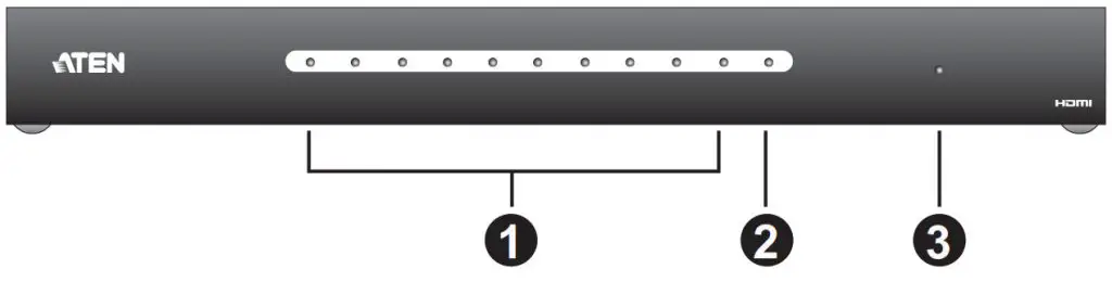
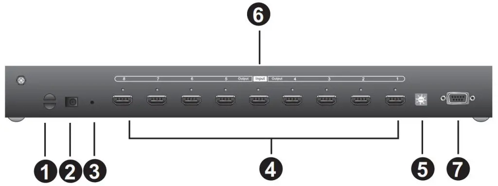
Front
| No. | Component | Description |
| 1 | Output Port LEDs (1~8) |
Lights to indicate there is a working connection to the display device(s) connected to the port(s). |
| 2 | Input LED | Lights to indicate that there is a working connection to the source device (i.e., computer). |
| 3 | Power LED | Lights green to indicate that the VS0108HA is receiving power and is up and running. Lights orange to indicate that the VS0108HA is in standby mode. |
Rear View

| No. | Component | Function |
| 1 | Cable Tie Slot | If you want to use a cable tie to gather the cables together, you can run it through this slot to attach it to the unit. |
| 2 | Power Jack | The power adapter cable plugs in here. |
| 3 | Firmware Upgrade button |
Press this to have the VS0108HA enter Firmware Upgrade Mode. When the upgrade is done, press it again to exit the mode. |
| 4 | HDMI Output port section |
The cables from your HDMI display devices plug into these ports. |
| 5 | EDID Mode Switch | Press this button to cycle through the EDID modes (0~7). Refer to page 11 for more details. |
| 6 | HDMI Input port | The cable from your HDMI source device plugs in here. |
| 7 | RS-232 Serial Port | This is the serial remote port for the output source selection and high-end system control, as well as for updating the device firmware. |
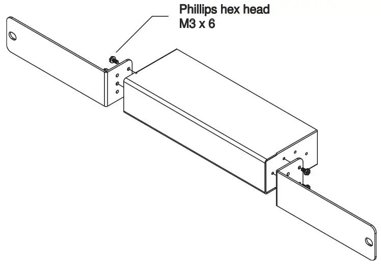
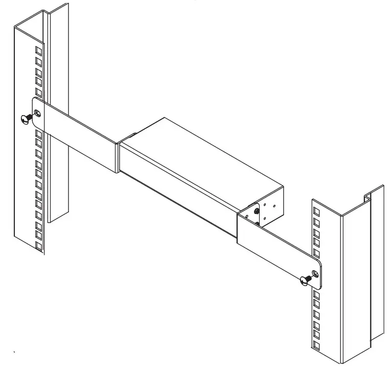
Mounting
For convenience and flexibility, the VS0108HA can be mounted on system racks. To rack mount a unit do the following:
1. Using the screws provided in the Rack Mount Kit, screw the mounting brackets into the side panels of the unit as shown in the diagram below:
Note: We recommend that you use M5 x 12 Phillips Type I cross, recessed type screws.
2. Screw the bracket into any convenient location on the rack.
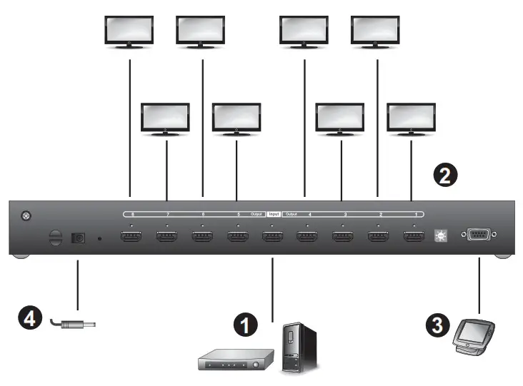
Installation
 1. Make sure that the power to all devices you will be installing has been turned off.
2. Make sure that all devices you will be installing are properly grounded.
Refer to the installation diagram (the numbers in the diagram correspond to the numbers of the steps) and do the following:
1. Use a Male-to-Male Type A HDMI cable to connect your computer or HDMI source device to the VS0108HA’s HDMI Input port.
2. Use Male-to-Male Type A HDMI cables to connect up to eight HDMI display devices to the HDMI Output ports.
3. (Optional) To edit the VS0108HA system settings through the RS-232 port, connect the hardware/software controller here.
4. Plug the power adapter that came with the VS0108HA into an
AC power source, then plug the power adapter cable into the splitter’s Power Jack
EDID
Extended Display Identification Data (EDID) is a data format that contains a display’s basic information and is used to communicate with the video source/system. The VS0108HA lets users select an EDID Mode, which sets how the source device acquires a display’s EDID.
EDID Mode Selection The EDID Mode can be selected using the EDID Mode Switch located at the VS0108HA unit’s rear panel.

To select an EDID, press the EDID Mode Switch to toggle between the ATEN default EDID and other EDID Settings (0~7) as follows:
♦ 0 (Default) – EDID is set to the ATEN default configuration.
The user can further choose between 14 ATEN default EDID settings available via the RS-232 command (see ATEN Default EDID, page 19)
♦ 1 (Port 1) – Implements the EDID of the connected display to Port 1, and passes it to the video source. The VS0108HA is able to copy the EDID of any connected display to the input source (see EDID Commands, page 16)
♦ 2 (Auto) – Implements the EDID of all connected displays. The VS0108HA uses the best resolution for all displays
♦ 3 (SW) – Uses the EDID configuration defined through the RS-232 command. Refer to EDID Commands, page 16 for more details
♦ 4 ~ 7- Reserved
EDID via RS-232
To use one of the 14 available ATEN default EDID configurations and to copy the EDID of any connected display to the input source, see EDID Commands, page 16.
Firmware Upgrade
Go to our Internet support site and choose the model name of your device (VS0108HA) to get a list of available Firmware Upgrade Packages. Choose the Firmware Upgrade Package you want to install (usually the most recent), and download it to your computer. Do the following steps:
1. Power off your VS0108HA by unplugging the power adapter.
2. Use a Serial RS-232 cable to connect a COM port on your computer to the VS0108HA RS-232 port.
3. Push and hold the Firmware Upgrade pushbutton on the unit’s rear panel, and power on the VS0108HA unit to enter the firmware upgrade mode.
4. Follow the step-by-step procedure displayed on your screen.
Installing the RS-232 Controller
In order to use the RS-232 serial interface to attach a high-end controller (such as a PC) to the VS0108HA, use a serial cable such as a modem cable. The end connecting to the VS0108HA should have a 9-pin male connector. Connect this to the serial interface on the rear of the VS0108HA. Refer to number 4 on the diagram on page 12.
Note: To configure the controller serial port, see page 14.
RS-232 Serial Interface
The VS0108HA’s built-in bi-directional RS-232 serial interface allows system control through a high-end controller, PC, and/or home automation/home theater software package.
Configuring the Serial Port
The controller’s serial port should be configured as follows:
| Baud Rate | 19200 |
| Data Bits | 8 |
| Parity | None |
| Stop Bits | 1 |
| Flow Control | None |
Switch Port
The available formulas for Switch Port commands are as follows:
Switch Command + Output Command + Port Number + Control
For example, to turn on output port 02, type the following:
sw o02 on
-or-
For example, to turn off output port 01, type the following:
sw o01 off
The following table shows the possible values for the Switch Port commands:
| Command | Description |
| sw | Switch command |
| Output Command | Description |
| o | Output command |
| Port Number | Description |
| yy | 01-08 port |
| * | All output ports (default) |
| Control | Description |
| on | Turn on the display |
| off | Turn off the display |
The following table shows the available command list:
| Command | Input | Port | Control | Enter | Description |
| sw | o | yy | on | [Enter] | Turn on display port yy |
| sw | o | yy | off | [Enter] | Turn off display port yy |
| sw | o | * | on | [Enter] | Turn on all displays |
| sw | o | * | off | [Enter] | Turn off all displays |
Note:
1. Each command string can be separated with space.
2. The Port Number command string can be skipped, and the default value will be used.
Baud Rate Setting Commands
You can set up the VS0108HA baud rate via RS-232.
The formula for Baud Rate setting commands is as follows: Baud + Baud Rate Setting value [Enter]
For example, to set the baud rate to 9600, input the following: baud 9600 [Enter]
The following tables show the possible values for the Control string:
| Command | Description |
| baud | Power On Detection command |
| Control | Description |
| 9600 | Uses 9600 baud rate |
| 19200 | Uses 19200 baud rate (default) |
| 38400 | Uses 38400 baud rate |
| 115200 | Uses 115200 baud rate |
The following table shows the available command list:
| Command | Control | Enter | Description |
| baud | 9600 | [Enter] | The VS0108HA implements 9600 baud rate setting |
| baud | 19200 | [Enter] | The VS0108HA implements 19200 baud rate setting (default) |
| baud | 38400 | [Enter] | The VS0108HA implements 38400 baud rate setting |
| baud | 115200 | [Enter] | The VS0108HA implements 115200 baud rate setting |
EDID Commands
You can set up which EDID mode the VS0108HA uses, select one of the 14 available ATEN default EDID configurations, and copy the EDID of any connected display to the input source with
the following command:
EDID Command + Control [Enter]
The following tables show the possible values and formats for the Control command:
| Command | Description |
| edid | Enable EDID selection |
| Control | Description |
| portyy | mplement the EDID of the connected display to Port yy, and pass it to the video source (Note: yy: 01-08) |
| auto | Implement the EDID of all connected displays. The VS0108HA uses the best resolution for all displays |
| defaultyy | Implements the specified ATEN default EDID configuration (Note: yy: 00-13, default is 00) |
Note: For the port and default command strings, the yy variable must be entered for the command to work.
The following table shows the available command list:
| Command | Control | Ente | Description |
| edid | portyy | [Enter] | The EDID from Port yy is passed tothe video source (yy: 01-08) |
| edid | auto | [Enter] | The VS0108HA implements the EDID of all connected displays and uses the best resolution for all displays (default) |
| edid | defaultyy | [Enter] | ATEN’s default EDIDyy is passed to the video source (yy: 00-13, default is 00) |
For more information on ATEN default EDID configuration, see ATEN Default EDID, page 19.
Read Commands
View information from the device using the following command:
Read Command + Port + Control [Enter]
The following tables show the possible values and formats for the Control command:
| Command | Description |
| read | eads and displays information from the VS0108HA |
The following table shows the available command list:
| Command | Enter | Description |
| read | [Enter] | Displays information such as firmware version and EDID |
Reset Commands
Reset the VS0108HA to default factory settings using the following command:
Reset Command [Enter]
The following tables show the possible value for the Control command:
| Command | Description |
| reset | Resets to factory default settings |
The following table shows the available command list:
| Command | Enter | Description |
| reset | [Enter] | Resets the VS0108HA |
Note: The Reset command reverts the Baud Rate to default, as well as switches all output devices on.
Verification
After entering a command, a verification message appears at the end of the command line as follows:
♦ Command OK – indicates that the command is correct and successfully performed by the switch
♦ Command incorrect – indicates that the command has the wrong format and/or values.
Powering Off and Restarting
If you power off the VS0108HA, follows these steps before powering it on again:
1. Power off the attached devices.
2. Unplug the power adapter cable from the VS0108HA.
3. Wait 10 seconds, and then plug the power adapter cable back in.
4. After the VS0108HA is powered on, power on the attached devices.
Note: Whenever the VS0108HA is powered on, it automatically selects the first port connected to a powered-on source device.
ATEN Default EDID
The ATEN default EDID configuration can be selected via the RS232 command line (see EDID Commands, page 16):
| Default EDID No. | Configuration |
| 0 | 720p video, 2 ch audio (default) |
| 1 | 1080p video, 2 ch audio |
| 2 | 1080p video, 5.1 ch audio |
| 3 | 1080p video, 7.1 ch audio |
| 4 | 1080i video, 2 ch audio |
| 5 | 1080i video, 5.1 ch audio |
| 6 | 1080i video, 7.1 ch audio |
| 7 | 3D 1080p, 2 ch audio |
| 8 | 3D 1080p, 5.1 ch audio |
| 9 | 3D 1080p, 7.1 ch audio |
| 10 | 1024 x 768 DVI format |
| 11 | 1280 x 1024 DVI format |
| 12 | 1920 x 1080 DVI format |
| 13 | 1920 x 1200 DVI format |
Specifications
| Function | VS0108HA | ||
| Display Connections | 8 | ||
| Connectors | Device | HDMI In | 1 x HDMI Type A Female (Black) |
| Display | HDMI Out | 8 x HDMI Type A Female (Black) | |
| Power Jack | 1 x DC Jack | ||
| RS-232 | 1 x DB-9 Female (Black) | ||
| LEDs | Output | 8 (Green) | |
| Input | 1 (Green) | ||
| Power | 1 (Green + Orange) | ||
| Video | HDTV resolution of 480p, 720p, 1080i, 1080p (1920×1080) and Ultra HD 4kx2k; VGA, SVGA, SXGA, UXGA, WUXGA (1920×1200) |
||
| Power Consumption | DC 5V, 13 W | ||
| Environment | Operating Temp. | 0-50°C | |
| Storage Temp. | -20-60°C | ||
| Humidity | 0-80% RH, Non-condensing | ||
| Physical Properties | Housing | Metal | |
| Dimensions (LxWxH) | 43.72 x 15.78 x 4.40 cm | ||
Limited Warranty
ATEN warrants its hardware in the country of purchase against flaws in materials and workmanship for a Warranty Period of two [2] years (warranty period may vary in certain regions/countries) commencing on the date of original purchase. This warranty period includes the LCD panel of ATEN LCD KVM switches. Select products are warranted for an additional year (see A+ Warranty for further details). Cables and accessories are not covered by the Standard Warranty.
What is covered by the Limited Hardware?
Warranty ATEN will provide a repair service, without charge, during the Warranty Period. If a product is a detective, ATEN will, at its discretion, have the option to (1) repair said product with new or repaired components, or (2) replace the entire product with an identical product or with a similar product that fulfills the same function as the defective product. Replaced products assume the warranty of the original product for the remaining period or a period of 90 days, whichever is longer. When the products or components are replaced, the replacing articles shall become customer property and the replaced articles shall become the property of ATEN.
To learn more about our warranty policies, please visit our website: http://www.aten.com/global/en/legal/policies/warranty-policy/
Compliance Statements
FEDERAL COMMUNICATIONS COMMISSION INTERFERENCE
STATEMENT
This equipment has been tested and found to comply with the limits for a Class A digital device, pursuant to Part 15 of the FCC Rules. These limits are designed to provide reasonable protection against harmful interference when the equipment is operated in a commercial environment. This equipment generates, uses, and can radiate radio frequency energy and, if not installed and
used in accordance with the instruction manual, may cause harmful interference to radio communications. Operation of this equipment in a residential area is likely to cause harmful interference in which case the user will be required to correct the interference at his own expense.
The device complies with Part 15 of the FCC Rules. Operation is subject to the following two conditions: (1) this device may not cause harmful interference, and (2) this device must accept any interference received, including interference that may cause undesired operation.
FCC Caution
Any changes or modifications not expressly approved by the party responsible for compliance could void the user’s authority to operate this equipment.
Warning
Operation of this equipment in a residential environment could cause radio interference.

Industry Canada Statement
This Class A digital apparatus complies with Canadian ICES-003.
CAN ICES-003 (A)/NMB-003 (A)
HDMI Trademark Statement
The terms HDMI, HDMI High-Definition Multimedia Interface, and the
HDMI Logo are trademarks or registered trademarks of HDMI Licensing
Administrator, Inc.

RoHS
This product is RoHS compliant.
About this Manual
This User Manual is provided to help you get the most from your system. It
covers all aspects of installation, configuration and operation. An overview of the information found in the manual is provided below.
Chapter 1, Introduction, introduces you to the VE803 system. Its purpose,
features and benefits are presented, and its front and back panel components are described.
Chapter 2, Hardware Setup, describes how to set up your installation. All necessary steps to prepare for operation are provided.
Chapter 3, Basic Operation, describes how to use the EDID switch and EQ switch to adjust the picture quality.
An Appendix, provides specifications and other technical information regarding the VE803.
Package Contents
The basic VE803 package consists of:
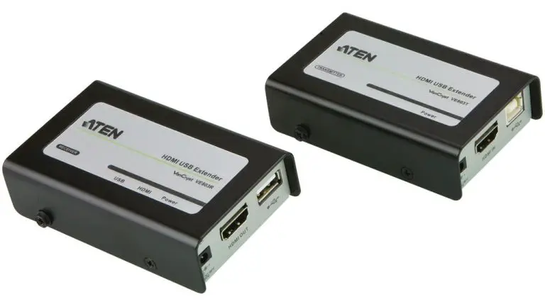
- 1 VE803T HDMI USB Extender
- 1 VE803R HDMI USB Extender
- 1 power adapter
- 1 USB cable (1.8 m)
- 1 mounting kit
- 1 user instructions*
Check to make sure that all the components are present and that nothing got damaged in shipping. If you encounter a problem, contact your dealer.
Read this manual thoroughly and follow the installation and operation procedures carefully to prevent any damage to the unit, and/or any of the devices connected to it.
| * Features may have been added to the VE803 since this manual was published. Please visit our website to download the most up-to-date version. |
User Information
Be sure to register your product at our online support center:
| International | http://eservice.aten.com/ |
For telephone support, call this number:
| International | 886-2-8692-6959 |
| China | 86-400-810-0-810 |
| Japan | 81-3-5615-5811 |
| Korea | 82-2-467-6789 |
| North America | 1-888-999-ATEN ext 4988 1-949-428-1111 |
All information, documentation, and specifications contained in this manual are subject to change without prior notification by the manufacturer. The manufacturer makes no representations or warranties, either expressed or implied, with respect to the contents hereof and specifically disclaims any warranties as to merchantability or fitness for any particular purpose. Any of
the manufacturer’s software described in this manual is sold or licensed as is. Should the programs prove defective following their purchase, the buyer (and not the manufacturer, its distributor, or its dealer), assumes the entire cost of all necessary servicing, repair and any incidental or consequential damages resulting from any defect in the software.
The manufacturer of this system is not responsible for any radio and/or TV
interference caused by unauthorized modifications to this device. It is the responsibility of the user to correct such interference.
The manufacturer is not responsible for any damage incurred in the operation
of this system if the correct operational voltage setting was not selected prior to operation. PLEASE VERIFY THAT THE VOLTAGE SETTING IS CORRECT BEFORE USE.
Conventions
This manual uses the following conventions:
| Monospaced | Indicates text that you should key in. |
| [ ] | Indicates keys you should press. For example, [Enter] means to press the Enter key. If keys need to be chorded, they appear together in the same bracket with a plus sign between them: [Ctrl+Alt]. |
| 1. | Numbered lists represent procedures with sequential steps. |
| ♦ | Bullet lists provide information, but do not involve sequential steps. |
| > | Indicates selecting the option (on a menu or dialog box, for example), that comes next. For example, Start > Run means to open the Start menu, and then select Run. |
 |
Indicates critical information. |
Product Information
For information about all ATEN products and how they can help you connect without limits, visit ATEN on the Web or contact an ATEN Authorized
Reseller. Visit ATEN on the Web for a list of locations and telephone numbers:
| International | http://www.aten.com/ |
| North America | http://www.aten-usa.com/ |
Introduction
Overview
The VE803 HDMI USB Extender extends HDMI signals up to 60 meters from the HDMI source using two Cat 5e cables. It is capable of sending 1080i signals up to 60 meters, and 1080p signals up to 40 meters.
The VE803 is equipped with USB connectors, which allow you to extend any USB device between the units. The USB feature also provides support for touch panel control, allowing you to control the local HDMI source device from the remote display, or control the remote display through the local unit.
The VE803 is ideal for transportation centers, medical facilities, shopping malls or anywhere touch panel control at a kiosk is required. For flexibility and convenience, the VE803 local unit can be powered via the USB cable when connected to an appropriate source device. The VE803 is HDCP compliant, providing an easy and ideal HDMI extender solution for any application
- Uses two Cat 5e cables to connect the local and the remote units
- Extends 1080p by 40m; extends 1080i by 60m
- Superior video quality – HDTV resolutions of 480p, 720p, 1080i, 1080p (1920×1080), VGA, SVGA, XGA, SXGA, UXGA and WUXGA (1920×1200)
- Supports USB touch panels
- 8-segment Equalization adjustment switch optimizes display quality
- Supports Dolby True HD and DTS HD Master Audio
- Built-in 8KV / 15KV ESD protection
- Transparent USB Support – supports all USB 2.0 full speed device (12 Mbps)
- USB 2.0 compatible
- Supports wide screen formats
- HDMI (3D, Deep Color); HDCP compatible – signaling rates up to 2.25 Gbits
- Transmitter unit powered via USB cable
Requirements
The following equipment must be installed on the source device or computer:
- HDMI Type A output connector(s)
- A display device or receiver with an HDMI Type A input connector
- Use HDMI cables to connect the HDMI source and display device to the VE803T and VE803R
- Use two Cat 5e cables to connect the VE803T to the VE803R
- Use standard USB cables with Type-A to Type-B connectors to connect USB devices
| Note: Cables are not included in this package. We strongly recommend that you purchase high-quality cables of appropriate length since this will affect the quality of the audio and video display. Contact your dealer to purchase the correct cable sets. |
Maximum cable distances are as follows:
- 40 m at 1080p @ 24-bit color depth
- 60 m at 1080i @ 24-bit color depth
Components
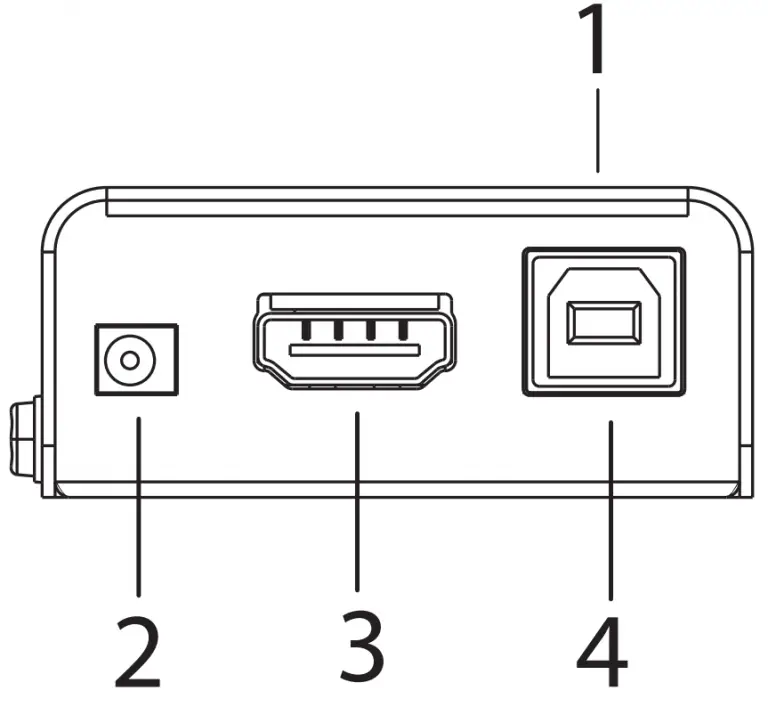
| No. | Component | Description |
| 1 | power LED | Lights (green) to indicate that the unit is receiving power. |
| 2 | power jack | The power adapter cable plugs connects here. |
| 3 | HDMI in | Connect the HDMI source device to this port. |
| 4 | USB Type-B port | Connect the source controller device to this port. |
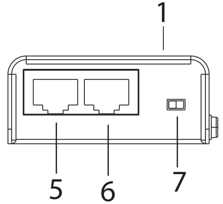
| 5 | HDMI port | Use a Cat 5e cable to connect the VE803T to the VE803R through this port. This channel is equipped with TMDS and sends the HDMI signal between the two units. |
| 6 | USB port | Use a Cat 5e cable to connect the VE803T to the VE803R through this port. This channel is equipped with DDC and sends the USB signal between the two units. |
| 7 | EDID switch | Use this switch to set the EDID mode (Bypass or Default). |
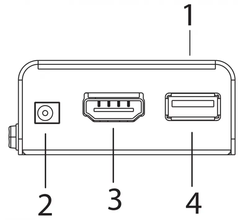
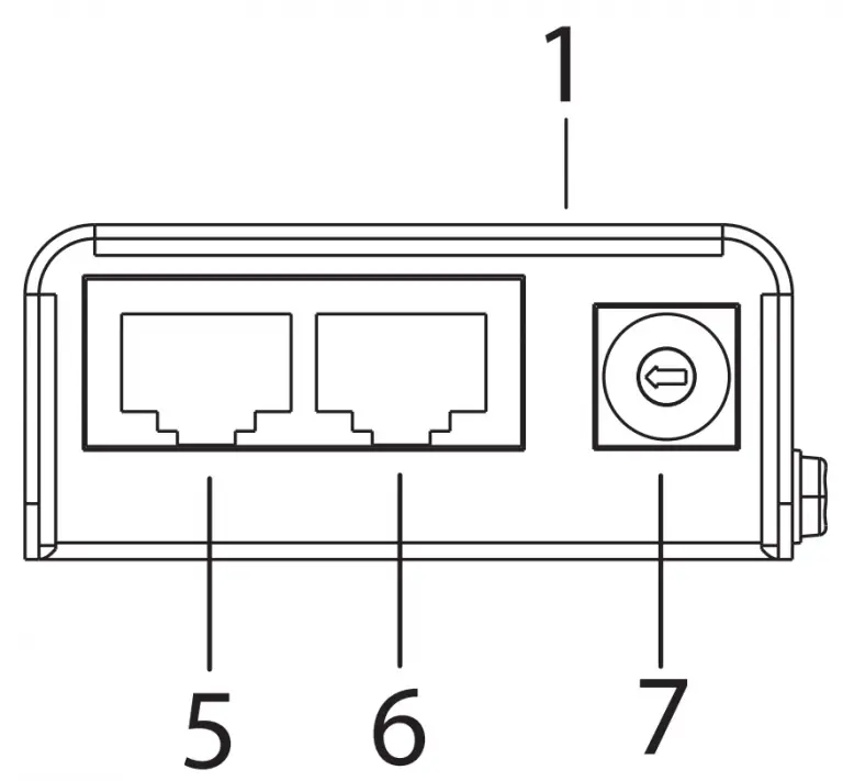
| No. | Component | Description |
| 1 | LEDs | Three LEDs – Power, HDMI, and USB – light (green) when the unit is properly connected to an appropriate source. |
| 2 | power jack | The power adapter cable plugs connects here. |
| 3 | HDMI out | Connect the HDMI display to this port. |
| 4 | USB Type-A port | Connect the display device to this port for controlling the source device. |
| 5 | HDMI port | Use a Cat 5e cable to connect the VE803T to the VE803R through this port. This channel is equipped with TMDS and sends the HDMI signal between the two units. |
| 6 | USB port | Use a Cat 5e cable to connect the VE803T to the VE803R through this port. This channel is equipped with DDC and sends the USB signal between the two units. |
| 7 | EQ switch | This 8-segment switch is used to adjust video quality. |
Hardware Setup
- Important safety information regarding the placement of this device is provided on page 11. Please review it before proceeding.
- Make sure that the power to all devices connected to the installation are turned off. You must unplug the power cords of any computers that have the Keyboard Power On function.
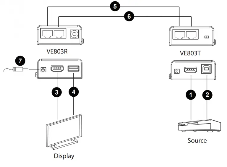
Installation
Setting up the VE803 is a matter of plugging in all the cables. Refer to the installation diagram on the next page (the numbers in the diagram correspond to the numbered steps) and do the following:
- Connect one end of an HDMI cable to the HDMI output port of your source device, and connect the other end to the HDMI Input port on the VE803T.
- Using the USB cable provided with this package, connect one end (Type-B connector) to the USB port on the VE803T, and the other end (Type-A connector) to the source device.
Note: The VE803T takes its power from this USB port. If the power supply is not enough to power on the VE803T, the unit can be plugged directly to a power outlet using a second power adapter (not supplied in this package). - Use an HDMI cable to connect your HDMI display to the HDMI Output port on the VE803R.
- Using a USB cable, connect one end (Type-A connector) to the USB port on the VE803R, and the other end to your HDMI display (or another device, such as a touchscreen).
Note: The USB cable for the VE803R is not supplied in this package. - Use a Cat 5e cable to connect the HDMI port on the VE803T to the HDMI port on the VE803R
- Use a second Cat 5e cable to connect the USB port on the VE803T to the USB port on the VE803R.
Note: For the VE803, a second Cate 5e cable is required if you need to use EDID bypass and HDCP authentication. - Using the power adapter supplied with this package, connect the VE803R to a power outlet.
- Turn on the HDMI source and display devices.
Installation Diagram
Basic Operation
Overview
This chapter describes the EDID and Equalization (EQ) switch functions to adjust the HDMI display and obtain the best video quality.
EDID Switch
Extended Display Identification Data (EDID) is a data format that contains a display’s basic information and is used to communicate with the video source/ system. In order to deliver the best video format, the VE803 is able to read the EDID information from the display and determine the best video resolution to send to the video source and program its resolution.
Use the EDID switch on the VE803T to manually switch EDID modes. There are two EDID modes to choose from:
- EDID/DDC Bypass- This mode bypasses the use of EDID / DDC, thus allowing the display information to come directly from the HDMI display to the source device, and determine the best resolution.
- ATEN Default- ATEN’s default EDID setting is sent to the video source to set the display resolution setting for your HDMI display.
Equalization Adjustment
The 8-segment Equalization (EQ) switch located on the VE803R unit is used to adjust the video quality. Use the EQ switch to adjust the equalization strength in order to improve a flickering or blinking image:
- 7 = Strongest EQ
- 0 = Weakest EQ
Appendix
Safety Instructions
- Read all of these instructions. Save them for future reference.
- Follow all warnings and instructions marked on the device.
- This product is for indoor use only.
- Do not place the device on any unstable surface (cart, stand, table, etc.). If the device falls, serious damage will result.
- Do not use the device near water.
- Do not place the device near, or over, radiators or heat registers.
- The device cabinet is provided with slots and openings to allow for adequate ventilation. To ensure reliable operation, and to protect against overheating, these openings must never be blocked or covered.
- The device should never be placed on a soft surface (bed, sofa, rug, etc.) as this will block its ventilation openings. Likewise, the device should not be placed in a built in enclosure unless adequate ventilation has been provided.
- Never spill liquid of any kind on the device.
- Unplug the device from the wall outlet before cleaning. Do not use liquid or aerosol cleaners. Use a damp cloth for cleaning.
- The device should be operated from the type of power source indicated on the marking label. If you are not sure of the type of power available, consult your dealer or local power company.
- To prevent damage to your installation it is important that all devices are properly grounded.
- Do not allow anything to rest on the power cord or cables. Route the power cord and cables so that they cannot be stepped on or tripped over.
- Position system cables and power cables carefully; Be sure that nothing rests on any cables.
- Never push objects of any kind into or through cabinet slots. They may touch dangerous voltage points or short out parts resulting in a risk of fire or electrical shock.
- Do not attempt to service the device yourself. Refer all servicing to qualified service personnel.
- If the following conditions occur, unplug the device from the wall outlet and bring it to qualified service personnel for repair.
♦ The power cord or plug has become damaged or frayed.
♦ Liquid has been spilled into the device.
♦ The device has been exposed to rain or water.
♦ The device has been dropped, or the cabinet has been damaged.
♦ The device exhibits a distinct change in performance, indicating a need for service.
♦ The device does not operate normally when the operating instructions are followed. - Only adjust those controls that are covered in the operating instructions.
Improper adjustment of other controls may result in damage that will require extensive work by a qualified technician to repair.
Technical Support
- For online technical support – including troubleshooting, documentation, and software updates: http://eservice.aten.com
- For telephone support, see Telephone Support, page vi:
| Email Support | [email protected] | |
| Online Technical Support | Troubleshooting Documentation Software Updates | http://www.aten-usa.com/support |
| Telephone Support | 1-888-999-ATEN ext 4988 | |
When you contact us, please have the following information ready beforehand:
- Product model number, serial number, and date of purchase.
- Your computer configuration, including operating system, revision level, expansion cards, and software.
- Any error messages displayed at the time the error occurred.
- The sequence of operations that led up to the error.
- Any other information you feel may be of help.
Specifications
| Function | VE803T | VE803R | |
| Connectors | HDMI In | 1 x HDMI Type A Female (Black) | N/A |
| HDMI Out | N/A | 1 x HDMI Type A Female (Black) | |
| USB | 1 x USB Type B Female (White) | 1 x USB Type A Female (White) | |
| HDMI/USB Port* | 2 x RJ-45 Female (Silver) | ||
| Power | 1 x DC Jack (Black) | ||
| Switches | EQ Compensation | N/A | 1 x 8-position switch |
| EDID Selection | 1 x slide switch | N/A | |
| LED | Power | 1 x Green | 1 x Green |
| HDMI | N/A | 1 x Green | |
| USB | N/A | 1 x Green | |
| Video Resolution | 1080p @ 60Hz, at 40m 1080i @ 60Hz, at 60m | ||
| Power Consumption | DC5V; 1W | DC5V; 3.9W | |
| Environment | Operating Temp. | 0–50ºC | |
| Storage Temp | -20–60ºC | ||
| Humidity | 0–80% RH, Non-condensing | ||
| Physical Properties | Housing | Metal | |
| Weight | 0.16kg | 0.16kg | |
| Dimensions (L x W x H) | 7.16 x 3.16 x 2.30 cm | 7.16 x 3.16 x 2.30 cm | |
| Note: *HDMI/USB Port is equipped with TMDS.DDC and sends the HDMI/USB signal between the two units. |
Limited Warranty
ATEN warrants its hardware in the country of purchase against flaws in materials and workmanship for a Warranty Period of two [2] years (warranty period may vary in certain regions/countries) commencing on the date of original purchase. This warranty period includes the LCD panel of ATEN LCD KVM switches. Select products are warranted for an additional year (see A+ Warranty for further details). Cables and accessories are not covered by the Standard Warranty.
What is covered by the Limited Hardware Warranty
ATEN will provide a repair service, without charge, during the Warranty Period. If a product is detective, ATEN will, at its discretion, have the option to (1) repair said product with new or repaired components, or (2) replace the entire product with an identical product or with a similar product which fulfills the same function as the defective product. Replaced products assume the warranty of the original product for the remaining period or a period of 90 days, whichever is longer. When the products or components are replaced, the replacing articles shall become customer property and the replaced articles shall become the property of ATEN.
To learn more about our warranty policies, please visit our website:
http://www.aten.com/global/en/legal/policies/warranty-policy/
© Copyright 2021 ATEN® International Co., Ltd.
Released: 8 April 2021 1:07 pm
ATEN and the ATEN logo are registered trademarks of ATEN International Co., Ltd. All rights reserved.
All other brand names and trademarks are the registered property of their respective owners.

Package Contents:
1 VS132A / VS134A / VS138A Video Splitter
1 Power Adapter
1 Quick Start Guide
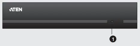
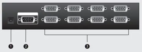
(A) Front View (VS138A)
(B) Rear View (VS138A)
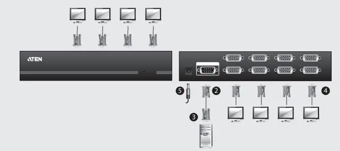
(C) Single Stage Installation

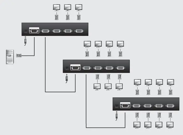
(D) Cascading
Requirements
Source Device
The following equipment must be installed on the computer or source device that is acting as the source of video content:
• HDB-15 output connector(s)
Display Device
• A display device or receiver with an HDB-15 input connector for each output port you will be installing
Cables
- A VGA cable for the source device you will be installing
- A VGA cable for each display device or receiver you will be installing
Note: VGA cables are not supplied with this package
Hardware Review
Front View (A)
- Power LED
Rear View (B)
- Power Jack
- Video In Port
- Video Out Ports
Installation
Single Stage Installation (C)
Setting up the VS132A / VS134A / VS138A is simply a matter of plugging in the cables. In a single stage installation, no additional video splitters are cascaded down from the first unit. Refer to the diagram as you follow the step by step directions below:
- Make sure that the computer and monitors you are using for the installation are all powered off.
- Plug the female end of a male-to-female VGA cable into the VS132A / VS134A / VS138A’s Video In port.
- Plug the male end of the VGA cable into the computer or source device’s video output port.
- Use 2/4/8 VGA cables to connect 2/4/8 displays to the VS132A / VS134A / VS138A’s Video Out ports.
Note: VGA cables do not come with the package. These must be purchased separately. - Plug the power adapter (supplied with this package) into an AC source; then plug the power adapter cable into the splitter’s power jack.
- Power on all equipment.
Cascading (D)
To provide video displays for more monitors, additional units can be cascaded. Use a high-density HDB-15 male/female video extender cable to connect any available Video Out port on the higher level Video Splitter to the Video In port of the lower level video splitter.
You can cascade as many video splitters as there are ports available, and all three models can be mixed on the same chain. Theoretically, there is no limit to the number of splitters that can be cascaded, but the quality will deteriorate as you get further and further away from the video signal.
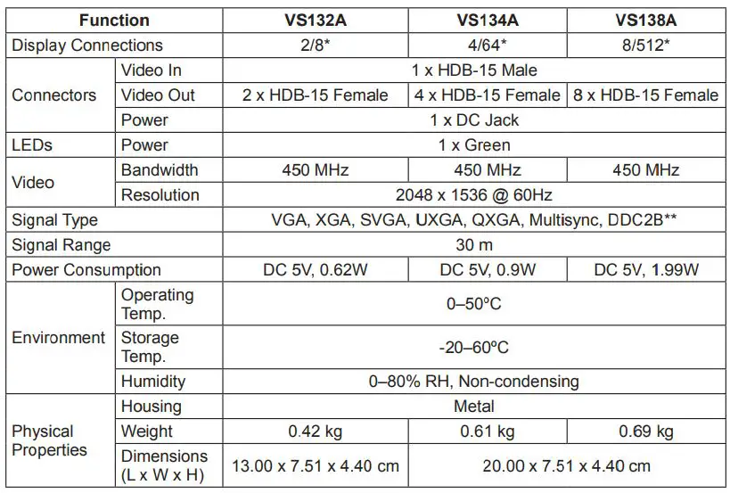
Specifications
Support and Documentation Notice
All information, documentation, firmware, software utilities, and specifications contained in this package are subject to change without prior notification by the manufacturer. To reduce the environmental impact of our products, ATEN documentation and software can be found online at http://www.aten.com/download/
Technical Support www.aten.com/support
Scan for more information
EMC Information
FEDERAL COMMUNICATIONS COMMISSION INTERFERENCE STATEMENT: This equipment has been tested and found to comply with the limits for a Class A digital device, pursuant to Part 15 of the FCC Rules. These limits are designed to provide reasonable protection against harmful interference when the equipment is operated in a commercial environment. This equipment generates, uses, and can radiate radio frequency energy and, if not installed and used in accordance with the instruction manual, may cause harmful interference to radio communications. Operation of this equipment in a residential area is likely to cause harmful interference in which case the user will be required to correct the interference at his own expense.
FCC Caution: Any changes or modifications not expressly approved by the party responsible for compliance could void the user’s authority to operate this equipment.
Warning: Operation of this equipment in a residential environment could cause radio interference.
This device complies with Part 15 of the FCC Rules. Operation is subject to the following two conditions:(1) this device mat not cause harmful interference, and(2) this device must accept any interference received, including interference that may cause undesired operation.
Important. Before proceeding, download the Installation and Operation Manual by visiting the website, www.aten.com and navigating to the product page. The manual includes important warnings, loading specifications and grounding instructions.
© Copyright 2019 ATEN® International Co., Ltd. ATEN and the ATEN logo are trademarks of ATEN International Co., Ltd. All rights reserved. All other trademarks are the property of their respective owners.
Part No. PAPE-1285-V00G
Printing Date: 10/2019

![]()