![]()
Owner’s Guide

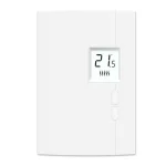
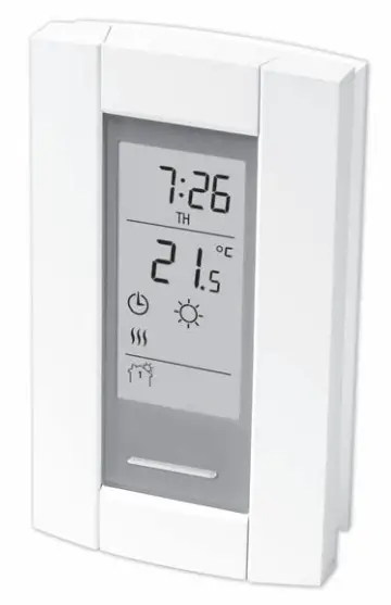
TH115 (120S/240S/240D)
Programmable thermostat

Read before installing
Models
- TH115-A-120S/U
- TH115-A-240D-B/U
- TH115-A-240S-B/U
- TH115-AF-024T/U
- TH115-AF-120S/U
- TH115-AF-12VDC/U
- TH115-AF-240S/U
Before you start
Read the entire document
CAUTION:
- Installation must be carried out by a certified electrician and must comply with national and local electrical codes.
- To prevent severe shock or electrocution, always cut the power at the service panel before working with wiring.
- Use this thermostat for resistive loads only.
- Do NOT install the thermostat in an area where it can be exposed to water or rain.
- Avoid locations where there are air drafts (top of the staircase, air outlet), dead air spots (behind a door), direct sunlight or concealed chimney or stove pipes (except for floor heating systems).
- For a new installation, choose a location about 1.5 m (5 ft.) above the floor.
- Install the thermostat on an inside wall facing the heating system (except for floor heating systems).
- Install the thermostat onto an electrical box.
- Use special CO/ALR solderless connectors if you connect the thermostat to aluminum wires.
- Keep the thermostat’s top and bottom air vents (openings) clean and unobstructed at all times..
About your thermostat
The TH115 programmable thermostat has three temperature control modes:
A mode: ![]() controls the ambient air temperature
controls the ambient air temperature
F mode: ![]() controls the floor temperature using an external temperature sensor
controls the floor temperature using an external temperature sensor
AF mode: ![]() controls the ambient air temperature
controls the ambient air temperature ![]() maintains the floor temperature within desired limits using an external temperature sensor
maintains the floor temperature within desired limits using an external temperature sensor
See page 9 on how to change the temperature control mode setting.
Supplied Parts
- One (1) thermostat
- Two (2) mounting screws
- One (1) floor sensor *
- One (1) flat-tip screwdriver *
- Four (4) solderless connectors for copper wires
* Select models only; required for floor heating applications only.
Controls
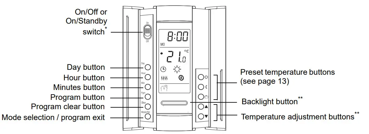
*Place at Off/Standby to cut power to the heater (e.g., in the summer). This will not affect the time and temperature settings.
**When the backlight button or either of the![]() buttons is pressed, the display illuminates for 12 seconds.
buttons is pressed, the display illuminates for 12 seconds.
Display
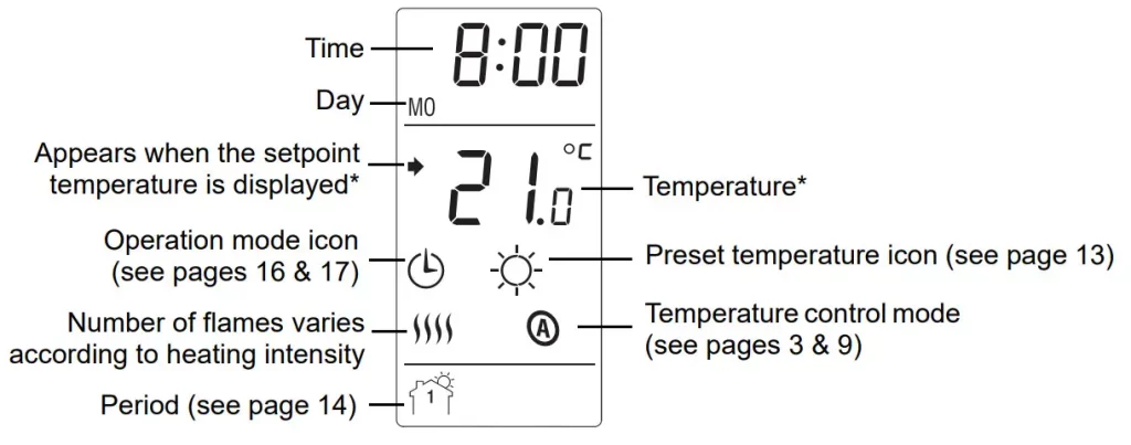
* The thermostat normally displays the actual (measured) temperature. To view the setpoint temperature, briefly press either of the![]() buttons. The setpoint will appear for 5 seconds. To change the setpoint temperature, press one of the
buttons. The setpoint will appear for 5 seconds. To change the setpoint temperature, press one of the ![]() buttons until the desired temperature is displayed. To scroll faster, press and hold the button.
buttons until the desired temperature is displayed. To scroll faster, press and hold the button.
Installing the thermostat
- Turn the heating system off at the main electrical panel.
- Loosen the bottom screw and remove the thermostat faceplate from its wallplate. (The screw cannot be completely removed.)
- Connect the thermostat to the load and to the power supply (see page 7).
- If the thermostat will be used in F or AF Mode (see page 9), connect the floor sensor (see page 8).
WARNING: For floor heating applications, you must install a separate ground protection device at the main electrical panel or use a thermostat with a built-in ground protection device. - If you wish to connect a remote control device, see page 8.
- Install the wall plate to the electrical box using the provided screws.
- Set the configuration switches on the back of the faceplate (see page 9).
- Install the faceplate back on the wall plate and tighten the screw.
- Apply power to the heating system at the main electrical panel.
Wiring diagram
NOTE: Connect the wires using the provided solderless connectors for copper wires.
- Insert the floor sensor cable through one of the two openings on the wall plate and connect the sensor wires to terminals 3 and 4 (no polarity).
• The sensor wires must not come in contact with the electrical wires and must be routed outside the electrical box and follow the wall down to the floor.
• Position the sensor cable such that it does not come in contact with the floor heating wires. The sensor must be centered between two-floor heating wires for the best temperature control.
• Do NOT staple the sensor head (the plastic end) to the floor. Doing so might damage the sensor. Any damage might not be noticeable during testing but can become apparent several days later. - If you wish to connect a remote control device (see page 17), insert the wires (use 18- to 22-gauge flexible wires) through one of the two openings on the wallplate and connect them to terminals 1 and 2 (no polarity).

Connecting the floor sensor / remote control
| # | Configurations | Up | Down |
| 1 | Display format | °F / 12 h | °C / 24 h |
| 2 | Early Start¹ | Enable | Disable |
| 3 | Temperature control mode² | F A | AF |
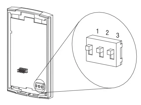
- Early Start is used in Automatic mode only. When Early Start is enabled (on), the thermostat determines when to start heating so the Comfort temperature is attained at the beginning of periods 1 and 3. When Early Start is disabled (off), heating starts only at the beginning of periods 1 and 3; thus there is a delay before the Comfort temperature is reached.
- See page 3. To select the F Mode, place the switch in the F position. To select the AF Mode, place the switch in the AF position and ensure that the temperature sensor is connected to the thermostat. To select the A Mode, place the switch in the AF position and ensure that the remote temperature sensor is NOT connected to the thermostat.
Time and day
To set the clock and the day:
- Press the Hour button to set the hour.
- Press the Min button to set the minutes.
- Press the Day button to set the day.
- Press the Mode/Ret button to return the thermostat to a normal display.
NOTE: The thermostat will automatically return to normal display if no button is pressed for 60 seconds.
Daylight Saving Time
When the Daylight Saving Time function is enabled (On), the thermostat automatically switches to Daylight Saving Time on the second Sunday of March and to normal time on the first Sunday of November.
NOTE: The Daylight Saving Time function is disabled (default setting) when the clock loses its setting.
To set the Daylight Saving Time function and to set the date:
- Press the Day button (3 seconds) until DLS appears on the screen.
- Press either of the
 buttons to toggle between On (enabled) and Off (disabled).
 - Press the Day button briefly. The year setting is displayed.
- Press either of the buttons to set the current year.
- Press the Day button briefly. The month setting is displayed.
- Press either of the buttons to set the current month.
- Press the Day button briefly. The date setting is displayed.
- Press either of the buttons to set the current date.
- Press the Mode/Ret button to return the thermostat to a normal display.
NOTE: The thermostat will automatically return to normal display if no button is pressed for 60 seconds.
Floor temperature limits (AF mode only)
WARNING: To avoid damaging your floor, follow your floor supplier’s recommendations regarding floor temperature limits.
The minimum and maximum floor temperature limits are 5.0°C (41°F) and 28.0°C (82°F) by default. To modify these limits, proceed as follows:
- Switch the thermostat Off.
- Press and hold the
 button.
 - Switch the thermostat back to On.
- Release the button when the minimum temperature limit (FL: LO) appears.
- Set the minimum temperature limit using the buttons.
- Press the button to display the maximum temperature limit (FL: HI).
- Set the maximum temperature limit using the buttons.
- Press Mode/Ret to return the thermostat to the normal display.
The thermostat has 3 preset temperatures. Their default settings are shown in the following table.
| Preset temperature | Intended use | Icon | A/AF modes | F mode |
| Comfort | When at home | 21.0°C (70°F) | 28.0°C (82°F) | |
| Economy | When asleep or away from home | 17.0°C (63°F) | 20.0°C (68°F) | |
| Vacation | During prolonged absence | 10.0°C (50°F) | 10.0°C (50°F) |
To use a preset temperature:
Briefly press the appropriate preset temperature button (, or ). The preset temperature will become the current setpoint and its icon will appear on the screen.
To modify a preset temperature:
- Press one of the buttons to display the desired temperature.
- Press and hold the appropriate preset temperature button (,
 or
or  ) until its icon is displayed.
Default schedule
The schedule consists of 4 periods per day, which represents a typical work day. The Comfort ( ![]() ) preset temperature is automatically used in Periods 1 and 3 and the Economy (
) preset temperature is automatically used in Periods 1 and 3 and the Economy (![]() ) preset temperature in Periods 2 and 4. You can program the thermostat to skip (cancel) the periods that do not apply to your situation. For example, you can skip periods 2 and 3 for the weekend.
) preset temperature in Periods 2 and 4. You can program the thermostat to skip (cancel) the periods that do not apply to your situation. For example, you can skip periods 2 and 3 for the weekend.
NOTE: If you wish to use only 2 periods, use the following combinations: “1 and 4” or “2 and 3”. Early Start (see page 9) will not work with any other combinations. You can have a different program every day; i.e., each period can start at a different time every day. The thermostat has been programmed with the following schedule.
| Period | Description | Setting | MO | TU | WE | TH | FR | SA | SU |
| Wake | Comfort |
6:00 AM | 6:00 AM | 6:00 AM | 6:00 AM | 6:00 AM | 6:00 AM | 6:00 AM | |
| Leave | Economy |
8:30 AM | 8:30 AM | 8:30 AM | 8:30 AM | 8:30 AM | –:– | –:– | |
| Return | Comfort |
5:00 PM | 5:00 PM | 5:00 PM | 5:00 PM | 5:00 PM | –:– | –:– | |
| Sleep | Economy |
11:00 PM | 11:00 PM | 11:00 PM | 11:00 PM | 11:00 PM | 11:00 PM | 11:00 PM |
Modifying the schedule
- Press PGM. Period 1 for Monday is displayed.
- To program another period, press Pgm to display that period.
- To program another day, press Day to display that day (hold for 3 seconds to select the entire week).
- Press Hour and Min to set the period start time or press Clear to skip (cancel) the period (–:– will be displayed).
- Repeat steps 2 to 4 to program another period.
- Press Mode/Ret to return the thermostat to the normal display.
NOTE: The thermostat will automatically return to normal display if no button is pressed for 60 seconds.
Running the schedule (Automatic mode)
In Automatic mode, the thermostat follows the programmed schedule (see page 14). To place the thermostat in this mode, press Mode/Ret until is displayed.
Temporary override of schedule
If you modify the setpoint temperature (by pressing the![]() ,
,![]() or
or![]() button) when the thermostat is in Automatic mode, the new emperature will be used until the beginning of the next period.
button) when the thermostat is in Automatic mode, the new emperature will be used until the beginning of the next period. ![]() flashes during the temporary override. You can cancel the temporary override by pressing Mode/Ret.
flashes during the temporary override. You can cancel the temporary override by pressing Mode/Ret.
Error Messages
![]() The measured temperature is below the display range. Heating is activated.
The measured temperature is below the display range. Heating is activated.![]() The measured temperature is above the display range. The heating is deactivated.
The measured temperature is above the display range. The heating is deactivated.![]() Verify the thermostat connection and sensor connection.
Verify the thermostat connection and sensor connection.
Technical Specifications
| Model | Supply | Maximum current | Maximum wattage | Wiring |
| 120S | 120 VAC, 50Hz/60Hz | 16.7 A | 2000 W | 4 wires / single pole |
| 240S | 240 VAC, 50Hz/60Hz 208 VAC, 50Hz/60Hz |
16.7 A | 4000 W 3470 W |
4 wires / single pole |
| 240D | 240 VAC, 50Hz/60Hz 208 VAC, 50Hz/60Hz |
15 A | 3600 W 3120 W |
4 wires / double pole |
Display range: 0°C to 70.0°C (32°F to 158°F)
Ambient setpoint range (A/AF modes): 5.0°C to 30.0°C (40°F – 86°F)
Floor setpoint range (F mode): 5.0°C to 40.0°C (40°F – 104°F)
Floor limit range (AF mode): 5.0°C to 40.0°C (40°F – 104°F)
Resolution: 0.5°C (1°F)
Heating cycle length: 15 minutes
Data protection: In the event of a power failure, most settings are saved. However, the time and Daylight Saving Time must be set if the power failure lasts more than 6 hours. The thermostat will return to the mode that was active prior to the power failure.
Warranty
Resideo warrants this product, excluding battery, to be free from defects in workmanship or materials, under normal use and service, for a period of three (3) years from the date of first purchase by the original purchaser. If at any time during the warranty period the product is determined to be defective due to workmanship or materials, Resideo shall repair or replace it (at Resideo’s option).
If the product is defective,
- return it, with a bill of sale or other dated proof of purchase, to the place from which you purchased it; or
- call Resideo Customer Care at 1-800-468-1502. Customer Care will make the determination whether the product should be
returned to the following address: Resideo Return Goods, 1985 Douglas Dr. N., Golden Valley, MN 55422, or whether a replacement product can be sent to you.
This warranty does not cover removal or reinstallation costs. This warranty shall not apply if it is shown by Resideo that the defect was caused by damage that occurred while the product was in the possession of a consumer.
Resideo’s sole responsibility shall be to repair or replace the product within the terms stated above. RESIDEO SHALL NOT BE LIABLE FOR ANY LOSS OR DAMAGE OF ANY KIND, INCLUDING ANY INCIDENTAL OR CONSEQUENTIAL DAMAGES RESULTING, DIRECTLY OR INDIRECTLY, FROM ANY BREACH OF ANY WARRANTY, EXPRESS OR IMPLIED, OR ANY OTHER FAILURE OF THIS PRODUCT. Some states do not allow the exclusion or limitation of incidental or consequential damages, so this limitation may not apply to you.
THIS WARRANTY IS THE ONLY EXPRESS WARRANTY RESIDE MAKES ON THIS PRODUCT. THE DURATION OF ANY IMPLIED WARRANTIES, INCLUDING THE WARRANTIES OF MERCHANTABILITY AND FITNESS FOR A PARTICULAR PURPOSE, IS HEREBY LIMITED TO THE THREE-YEAR DURATION OF THIS WARRANTY. Some states do not allow limitations on how long an implied warranty lasts, so the above limitation may not apply to you.
This warranty gives you specific legal rights, and you may have other rights which vary from state to state. If you have any questions concerning this warranty, please write Resideo Customer Care, 1985 Douglas Dr, Golden Valley, MN 55422 or call 1-800-468-1502.
![]()
![]()
![]() www.resideo.com
www.resideo.com
Resideo Technologies, Inc.
1985 Douglas Drive North, Golden Valley, MN 55422
69-2617EFS—03 M.S. Rev. 05-20 | Printed in United States | Imprimé aux États-Unis | Impreso en EE. UU.
© 2020 Resideo Technologies, Inc. All rights reserved.
The Honeywell Home trademark is used under license from Honeywell International, Inc.