![]() INSTALLATION INSTRUCTIONS
INSTALLATION INSTRUCTIONS
TWO-STAGE HEAT PUMPS
LOW VOLTAGE
CONTROL CIRCUIT WIRING
Models:
T**S T**S*D C**H
INSTALLATION
TABLE 1
Diagram to Use With Unit and Vents
| Model Series | No Vents | ERV MFAD CRV |
CRVMWH-3 CHCRV-5 |
Economizer “E” Vent Option | T, W, S ECONOMY |
| Vent Code | X | R, M, V, P | C | E | T, W, S |
| T**S / C**H | 1 | 2 | 9 & 10 | 3 | 7 |
| T**S*D | 4 | 5 | 9 & 10 | 6 | 8 |
LOW VOLTAGE WIRING
230/208V, 1 phase and 3 phase equipment dual primary voltage transformers. All equipment leaves the factory wired on 240V tap. For 208V operation, reconnect from 240V to 208V tap. The acceptable operating voltage range for the 240V and 208V taps are:
TABLE 2
Operating Voltage Range
| Tap | Range |
| 240V | 253 – 216 |
| 208V | 220 – 187 |
NOTE: The voltage should be measured at the field power connection point in the unit and while the unit is operating at full load (maximum amperage operating condition).
An 18 gauge copper, color-coded thermostat cable is recommended. The connection points are shown in Table 2.
Low Voltage Connection
These units use a grounded 24-volt AC low voltage circuit.
The “R” terminal is the hot terminal and the “C” terminal is grounded.
“G” terminal is the fan input.
“Y” terminal is the compressor input Stage 1.
“B” terminal is the reversing valve input. The reversing valve must be energized for heating mode.
“R” terminal is the 24 VAC hot.
“RT” terminal is the 24 VAC hot from the transformer (used with “R” for fire/smoke shutdown).
“C” terminal is the 24 VAC grounded.
“Y1” terminal is the compressor input Stage 2.
“L” terminal is compressor lockout output. This terminal is activated on a high or low-pressure trip by the electronic heat pump control. This is a 24 VAC output.
“W2” terminal is second stage heat (if equipped).
“O1” terminal is the ventilation input. This terminal energizes any factory-installed ventilation option.
“E” terminal is the emergency heat input. This
terminal energizes the emergency heat relay.
“W3” terminal is the dehumidification input. This terminal energizes the compressor, blower, and threeway valve. This applies only to models equipped for dehumidification
sequence.
LOW VOLTAGE CONNECTIONS FOR DDC CONTROL
| FOR DDC CONTROL Fan Only Cooling Mode 1st Stage Cooling Mode 2 nd Stage Heat Pump Heating 1 st Stage Heat Pump Heating 2 nd Stage 3 rd Stage Heating w/Heat Pump (if employed) Ventilation Emergency Heat Dehumidification |
Energize G Energize Y, G Energize Y, Y1, G Energize Y, G, B Energize Y, Y1, B, G Energize G, W2, Y, B, Y1 Energize G, O1 Energize B, W2, E, G Energize W3 |
TABLE 3
Wall Thermostat
| Part Number | Predominate Features |
| 8403-060 (1120-445) |
3 stage Cool; 3 stage Heat Programmable/Non-Programmable Electronic HP or Conventional Auto or Manual changeover Dehumidification Output |
TABLE 4
Humidity Controls
| Part Number | Predominate Features |
| 8403-038 (H600A1014) |
SPDT switching, pilot duty 50VA @ 24V Humidity range 20-80% RH |
| 8403-047 (H200-10-21-10) |
Electronic dehumi distat SPST closes-on-rise Humidity range 10-90% with adjustable stops |
TABLE 5
CO2 controller
| Part Number | Predominate Features |
| 8403-067 | Normally Open SPST relay closes on-rise a 24V dual-wavelength sensor. Default setting 950ppm, adjustable to 0-2000ppm Default off setting 1000ppm, adjustable to 0-200 ppm can be calibrated |
TABLE 6
Thermostat Wire Size
| Transformer VA |
FLA | Wire Gauge | Maximum Distance In Feet |
| 55 | 2.3 | 20 gauge 18 gauge 16 gauge 14 gauge 12 gauge |
45 60 100 160 250 |
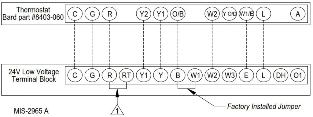
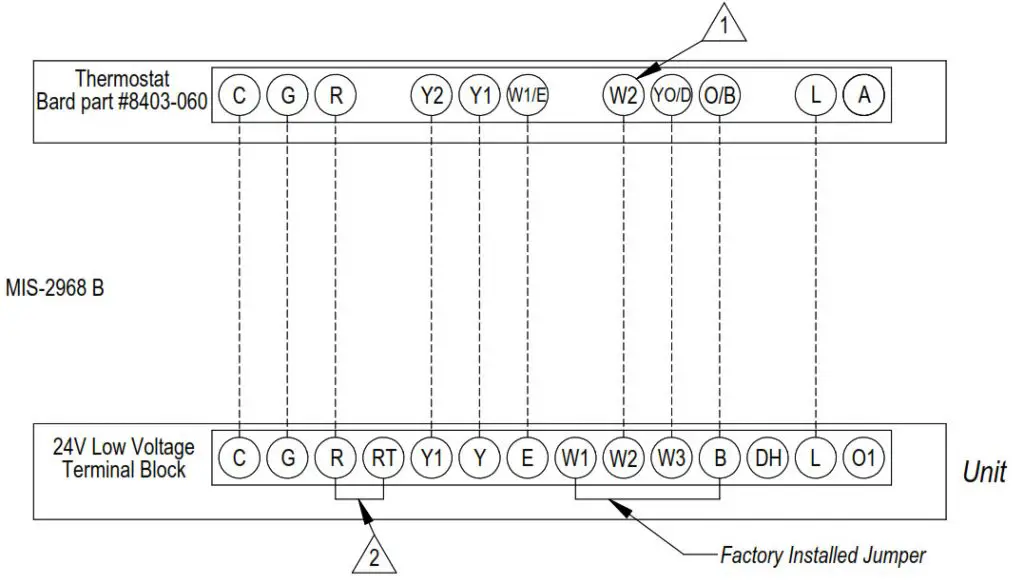
FIGURE 1
Low Voltage Wiring Diagram:
Heat Pump With Optional Electric Heat
No Economizer or Ventilation Packages

- Factory-installed jumper (on applicable models).
Remove jumper and connect to N.C fire alarm circuit if emergency shutdown required.
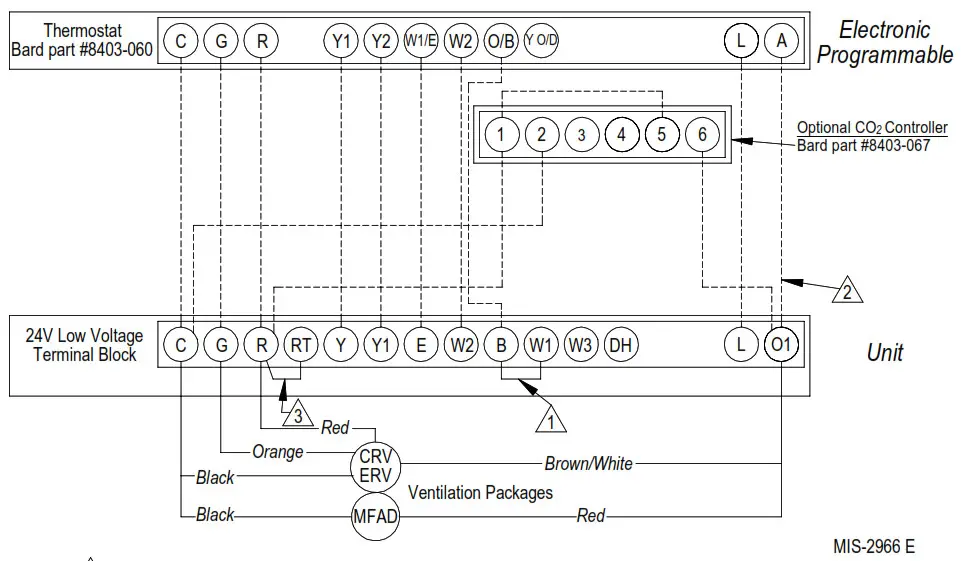
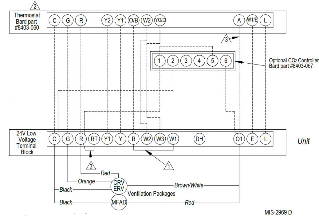
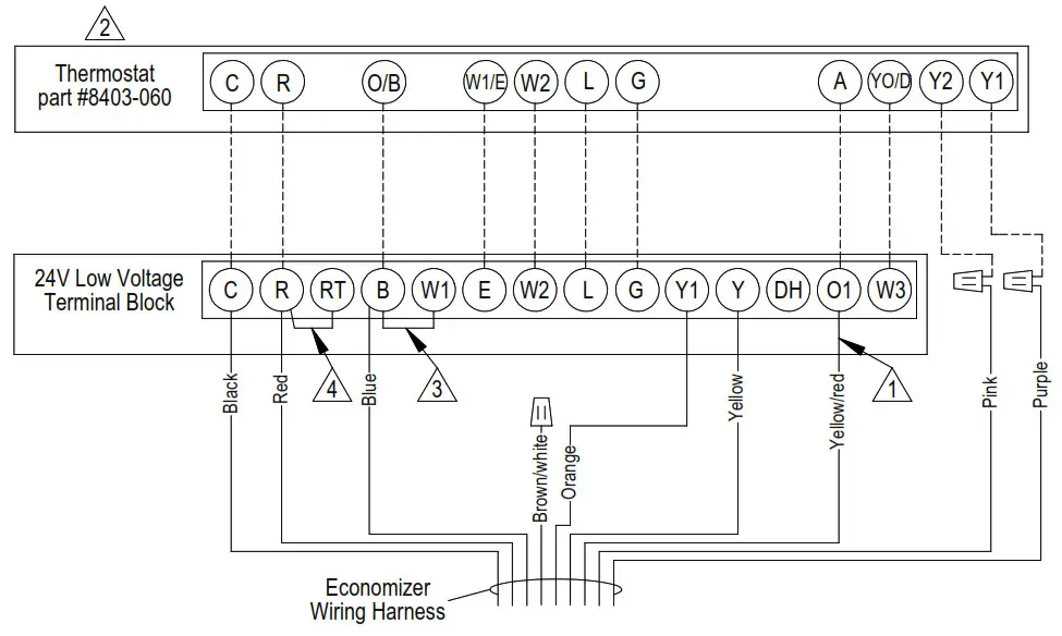
FIGURE 2
Low Voltage Wiring Diagram:
Heat Pump With Optional MFAD, CRV & ERV
Ventilation Packaging With Programmable Thermostat
- Factory Jumper Installed
- Do not connect “A” from tstat #8403-060
if an optional CO controller is used. - Factory-installed jumper (on applicable models).
Remove jumper and connect to N.C fire alarm
circuit if the emergency shutdown is required.
FIGURE 3
Low Voltage Wiring Diagram:
Heat Pump With Optional Economizer
- Factory-installed jumper (on applicable models).
- Remove jumper and connect to N.C fire alarm circuit if the emergency shutdown is required.
Factory Jumper Installed. - Must be configured for economizer with YO/D output to be active as first stage cooling.
- These wires are used in special control applications only.
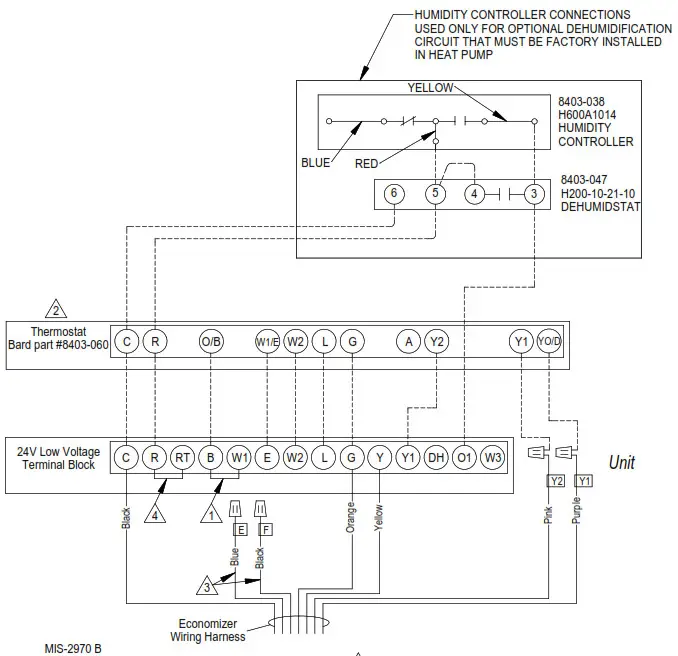
FIGURE 4
Low Voltage Wiring Diagram:
Heat Pump With Dehumidification Sequence and No Ventilation Package
Using Thermostat #8403-060 Combination Temperature & Humidity Controller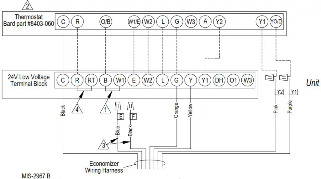
- Must be configured for “no economizer” to make YO/D output active for humidity control.
- Factory-installed jumper (on applicable models).
Remove jumper and connect to N.C fire alarm
circuit if emergency shutdown required.
FIGURE 5
Low Voltage Wiring Diagram:
Heat Pump With Dehumidification Sequence & Optional MFAD, CRV & ERV Ventilation
Packaging Using Electronic Thermostat With Combination Temperature & Humidity Control
Packaging using Electronic Thermostat with Combination Temperature and Humidity Control with Optional CO2 Controller
- Factory Jumper Installed
- Must be configured for “no economizer” to make YO/D output active for humidity control.
- Factory-installed jumper (on applicable models).
Remove jumper and connect to N.C fire alarm circuit if the emergency shutdown is required.
FIGURE 6
Low Voltage Wiring Diagram:
Dehumidification Heat Pump With Optional Economizer
- Factory Jumper Installed.
- Must be configured for economizer with YO/D output to be active as first stage cooling.
- Factory-installed jumper (on applicable models).
- These wires are used in special control applications only.
- Remove jumper and connect to N.C fire alarm circuit if emergency shutdown required.
FIGURE 7
Low Voltage Wiring Diagram:
2 Stage Heat Pump With Optional Electric Heat
With ECONWM* Style Economizer
 MIS-2982 C
- Must be energized to enable minimum position. NOTE: Economizer Control Default Setting is 10V (100%). Depending upon application may require setting to lower value.
- Must be configured for heat pump and economizer to enable YO/D output to be active as 1st-stage cooling
- Factory Jumper Installed.
- Factory-installed jumper (on applicable models).
Remove jumper and connect to N.C fire alarm circuit if the emergency shutdown is required.
FIGURE 8
Low Voltage Wiring Diagram:
2 Stage Heat Pump With Dehumidification & Optional Electric Heat
With ECONWM* Style Economizer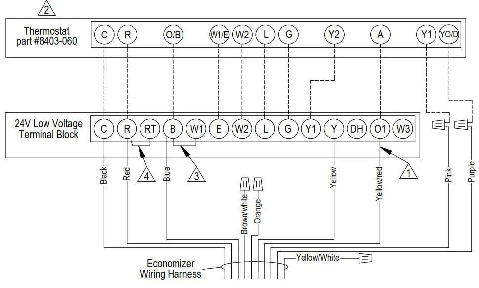 MIS-2999 A
- Must be energized to enable minimum position. NOTE: Economizer Control Default Setting is 10V (100%). Depending upon application may require setting to lower value.
- Must be configured for the heat pump to enable YO/D output to be active dehumidification output
- Factory Jumper Installed.
- Factory-installed jumper (on applicable models).
Remove jumper and connect to N.C fire alarm circuit if emergency shutdown required.
FIGURE 9
Low Voltage Wiring Diagram:
2 Stage Heat Pump With CHCRV-5 or CRVMWH-3
Vent Option Package With Programmable Thermostat
With Optional On/Off CO2 Controller
 Factory Jumper Installed
- Do not connect “A” from tstat #8403-060 if an optional CO2 controller is used.
- Wire only needed for dehumidification units
- Must be configured to programmable and fan set to programmed for the “A” output to function during scheduled occupied periods
- Factory-installed jumper (on applicable models).
Remove jumper and connect to N.C fire alarm circuit if the emergency shutdown is required.
FIGURE 10
Low Voltage Wiring Diagram:
2 Stage Heat Pump With CHCRV-5 or CRVMWH-3
Vent Option Package With Programmable Thermostat
With Optional Modulating CO2 Controller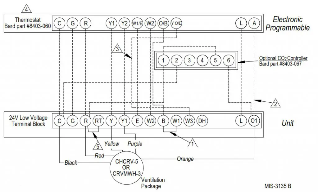 MIS-3334 A
- Factory Jumper Installed
- Wire only needed for dehumidification units set to program for the “A” output to function Must be configured to programmable and fan during scheduled occupied periods
- Factory-installed jumper (on applicable models).
- Remove jumper and connect to N.C fire alarm circuit if the emergency shutdown is required.