![]()


rev. 2
USER MANUAL
1. INTRODUCTION
We are delighted you have chosen to buy our Dark Base PC case. Please read the information here and carefully follow all the instructions prior to installation. Should you have further questions, please contact our customer service. See contact information in the manufacturer’s details section.
Warranty
- 3-year manufacturer’s warranty for the consumer (original purchase from authorized be quiet! dealers only)
- Your original receipt of purchase will be required before warranty services are rendered. Please store it carefully.
- Manipulations and/or technical modifications of any kind, or damage due to the application of mechanical force, will void your warranty.
- To read the warranty terms and conditions in full, see Service/Warranty Conditions on our website at bequiet.com.
Our General Terms and Conditions of Business also apply. For details please refer online under bequiet.com.
Manufacturer’s details
Listan GmbH & Co. KG | Biedenkamp 3a | 21509 Glinde | Germany
Visit the contact section on bequiet.com for the right regional service information.
Monday through Friday 09:00 17:30 (UTC+1)
Tel. 0049 40 736 7686 – 44 Fax 0049 40-7367686-69
Email: [email protected]
Website: www.bequiet.com
Copyright
- You are not allowed to reproduce, disclose, publish or store the contents of this documentation, or excerpts of it, without the prior written consent of Listan.
- be quiet! is a registered trademark of Listan GmbH & Co. KG. Other products and company names mentioned in this documentation may be the brands or trademarks of their respective owners.
- In accordance with company policy, all Listan products are subject to ongoing development. Listan reserves the right to make changes and improvements to any product described in this documentation without prior notice.
- Under no circumstances shall Listan be held liable for loss of data or income, or for any specific, incidental, direct, or indirect damage, however it arises.
- The content of this documentation represents the status at time of writing. Listan does not assume, whether expressed or implicit, any liability for the correctness or completeness of the content of this documentation, including, but not limited to the implicit guarantee of market suitability and fitness for a particular purpose, unless applicable laws or jurisdiction specifically stipulate such a liability.
Listan reserves the right to make changes to this documentation or to withdraw the documentation at any time without prior announcement.
4
2. SPECIFICATIONS
| Dimensions (W x H x D in mm) | 243 x 586 x 577 |
| Case type | Full tower |
| Material | 0.8mm 1mm SECC, 0.8mm aluminum, ABS plastic,
4mm tinted and tempered glass |
| Motherboard compatibility | E-ATX, XL-ATX, ATX, M-ATX, Mini-ITX |
| Front I/O connectors | 2x USB 3.0, 1x USB 3.1 Type C Gen. 2, 1x USB Quick Charging Option, HD audio (microphone + headphones), RGB control switch, HDD status display |
| Fan controller | 8x PWM stepless control / PWM hub |
| Max. CPU cooler height (mm) | 185 |
| Max. graphics card lenght (mm) | 325 / 470 (without HDD bracket) |
| Max. PSU length (mm) | 150 - 284 |
| PCI slots | 8 |
| 5.25″ bay | 2 |
| 3.5″ bay | 7 (5 ex works) |
| 2.5″ bay | 14 (10 ex works) |
| Case fans (mm) / (rpm) | Front: 2x Silent Wings 3 140 / 1,600 | Rear: 1x Silent Wings 3 140 / 1,600 |
| Optional case fans (mm) | Front: 1x 140 (without ODD cage, bracket included) T |
| Optional radiator installation (mm) | Front: 120, 140, 240, 280, 360, 420 Top: 120, 140, 180, 240, 280, 360, 420 Rear: 120, 140 |
| Additional features | Wireless charger for Qi enabled devices, switchable multi mode, multi color and expandable RGB LED lightning (white, red, green, blue, orange, purple), supports motherboard LED control |
5
3. CONTENTS
| Images | Part Name | Amount | Usage |
 |
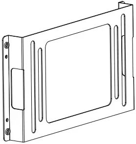
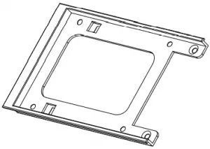
LCS bracket | 1 | Attaching liquid cooling pumps, etc. |
 |
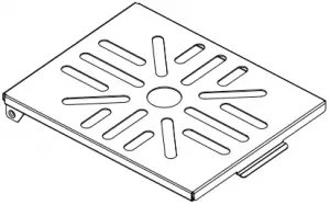
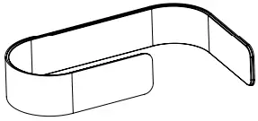
Fan bracket | 1 | Mounting a third fan on the front |
 |
HDD screw | 20 | Affixing the HDD |
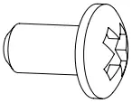 |
M3 screw | 8 | Fastening the SSD |
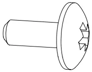 |
6#32 screw | 14 | Affixing the motherboard and SSD bracket |
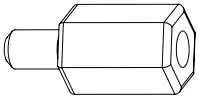 |
Stand-off screw | 3 | Securing an E-ATX motherboard |
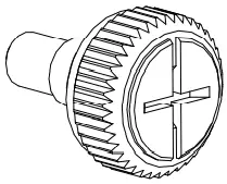 |
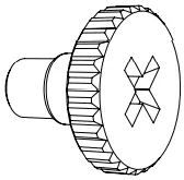
Knurled-head M3 | 8 | Affixing an ODD |
 |
Cable ties | 6 | Cable management |
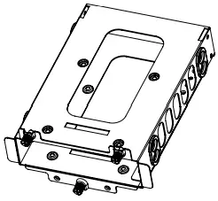 |
HDD cage | 3 | Installation of extra hard disks |
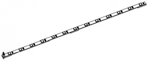 |
LED strip | 2 | Lighting |
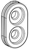 |
HDD rubber decoupling | 12 | Sound isolation of HDD cage |
 |
Double HDD slot cover | 1 | Covering the dual HDD slot |
 |
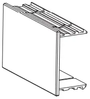
SSD bracket | 1 | Fixing an SSD on the PSU shroud |
6
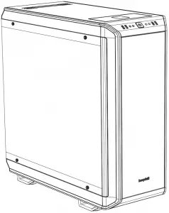
4. EXPLODED VIEW AND DESCRIPTION OF PARTS
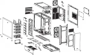
| A | Side window of tempered glass | Q | Front I/O panel |
| B | Fastening screws | R | Case body |
| C | ODD cage | S | Floor air filter |
| D | HDD cage | T | Case floor |
| E | PSU mounting | U | Silent Wings 3 fan |
| F | Double HDD slot cover | V | SSD bracket |
| G | HDD slot covers | W | PCB panel |
| H | Rear slot covers | X | Motherboard tray |
| I | Rear PSU shroud | Y | Case front |
| J | HDD panel | Z | ODD covers |
| K | Front of the PSU shroud | ||
| L | SSD bracket | a | Front air filter |
| M | Mounting for PSU shroud | b | Door |
| N | Mounting for PSU shroud | c | Side panel |
| O | Top cover of PSU shroud | d | Filter in the side panel |
| P | Top cover of case | e | 2-stepped opening in the side panel |
7
4.1 Front I/O and media ports
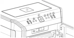
| A | USB 3.0 | F | USB 3.1 Type C Gen. 2 |
| B | HD audio (microphone and audio) | G | Quick charging option |
| C | Power button | H | Stepless fan controller |
| D | LED control switch | I | Qi charging station |
| E | HDD LED |
4.2 I/O ports
The front I/O ports that are provided require connections to your motherboard.
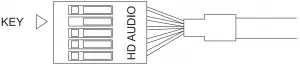
HD audio (headphone and microphone sockets)
Determine the HD audio pin connectors on your motherboard and insert the HD audio cables into the sockets allocated there. You will find information about the pin assignment of your motherboard in the motherboard handbook.
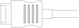
USB 3.1 Type C Gen. 2
Locate the USB 3.1 Type C pin connector on your motherboard and attach the USB 3.1 Type C cable using the designated sockets there.
USB 3.0
Find the USB 3.0 pin connectors on your motherboard and plug the USB 3.0 cable into the sockets allocated there. You will find information about the pin assignment of your motherboard in the motherboard handbook.
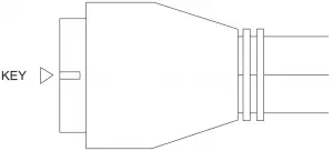
On/off switch, LED power indicator, HDD activity indicator
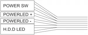 The illustrated plug connects the power switch and the case’s LED indicators with your motherboard. Take care to use the correct polarity with the LEDs. Your motherboard handbook will provide information on the correct connections.
8
4.3 PCB panel ports
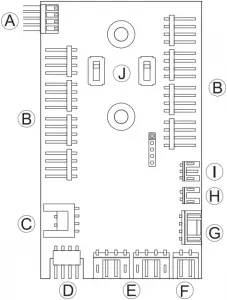
| A | PWM connector to the motherboard |
| B | PWM connector to the fans |
| C | LED connector to the motherboard |
| D | LED output for added external LEDs |
| E | Connector for the supplied LEDs |
| F | Connector for the Qi charger |
| G | SATA power connector |
| H | LED switch connector |
| I | Connection cable for fan controller slider switch |
| J | Switches for choosing between Silence and Performance modes |
4.4 Use of fan controller
The fan controller has two modes of operation.
1. Automatic operation
In this case the PWM signal of the motherboard is used and the speed of all PWM fans connected is automatically regulated by the motherboard. To enable this the slider switch must be positioned at position “0” completely to the left. For the automatic PWM fan controller to function, a cable must connect port “A” on the PCB panel to the PWM connector on your motherboard. Lacking this connection it is only possible to regulate the speed of the fans connected manually.
2. Manual control
Whenever the fan controller slider switch is moved rightwards away from its far left position, the PWM signal is ignored and the speed of the fans is manually controlled in a stepless range. In total eight PWM fans can be connected to the fan controller PCB. These eight sockets are divided into two channels (left and right) each with four connections. By setting the switches “J” on the PCB it is possible to choose between Silence and Performance modes independently for both of these channels. According to these switch positions the range of fan speeds possible are 400 1,040rpm in Silence mode and 800 1,600rpm in Performance mode.
If the slider switch is returned to its starting position “0” on the far left, the PWM signal regains control of fans.
9
4.5 Installation and handling of the LEDs
It is possible to freely position the LED lighting supplied in the case to suit your system setup by affixing and connecting the adhesive strips. The LED strips must be connected to connector “E” on the PCB panel.
Description of the LEDs
The LED lighting included in the scope of delivery is controllable in several modes of color and operation. Connector “D” on the PCB panel can be used to connect additional LED lighting strips up to a maximum of 24 watts for lighting the interior of the case. It is also possible to link the LED strips supplied directly together and in this way extend them.
WARNING! Only 12V LEDs may be connected.
In manual mode by briefly pressing switch “D” on the front panel it is possible to cycle through the colors. When “breath mode” is enabled there is an intermediate step between each color.
| 1 | White | 8 | Blue breath |
| 2 | White breath | 9 | Orange |
| 3 | Red | 10 | Orange breath |
| 4 | Red breath | 11 | Purple |
| 5 | Green | 12 | Purple breath |
| 6 | Green breath | 13 | Breath mode alternately in all colors |
| 7 | Blue | 14 | LEDs off |
Synchronized operation
To toggle between manual and synchronized operation hold down switch “D” on the front panel for about three seconds.
In synchronized operation, connector “C” on the LED controller PCB is connected to the socket designated for RGB LED on the motherboard. The integrated lighting is then controlled by the motherboard, with the same range of colors.
For information about operation of the LED controller of your motherboard please refer to the motherboard handbook.
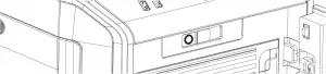
4.6 Charging station for Qi enabled devices
The preinstalled charging station provides contactless charging of any device that conforms to the Qi standard. If your device (e.g. your smartphone) is so equipped you can charge your device by simply placing it on area “I” on the top of the case, without the need to plug it in.
In so doing, make sure you place the device so that its charge receptor is positioned centrally on charging surface “I”.
10