Setup Manual

BLTouch auto Bed Levelling Sensor
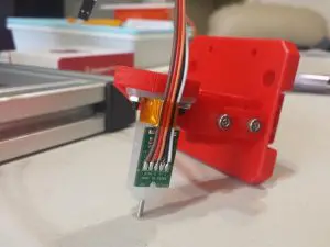
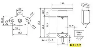
The mount needs to be adjustable so that the distance between the bottom of the sensor (not the pin) needs to be 8.3mm above the tip of the nozzle. The sensor should also be at least 15mm away from the hot bits.
Electrical
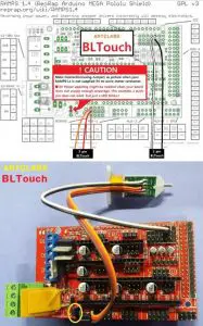
The BLTouch sensor has 5 wires, 3 to the first servo connection and 5v and 2 to the Z min end stop, negative and signal pins. NOTE: A link is needed between VCC and 5V in order to extend 5V to the servo connector pins. The scheme below suits the Aurdino/RAMPS used on my printer. There are many other ways to power it shown at https://plus.google.com/u/0/collection/8sQ5DB
Firmware
The BLTouch needs changes made to the configuration.h file in the Marlin source code. The required changes are similar to how you would setup a mechanical servo sensor.
The changes needed vary a lot between the different versions of Marlin. Between the latest stable version 1.02 and 1.1.0 RC3 release candidate there changes to layout. The info in this section is information only and not a complete “how to”.
Hopefully your printer manufacture will be able to provide the firmware ready to go in the future. If not use google and YouTube as resources.
Example only RC2
In Configuration.h: 1.Invert Z minconst bool Z_MIN_ENDSTOP_INVERTING = false;
2. Enable servo and set endstop angles to the S codes provided by BLTouch:#define SERVO_ENDSTOPS {-1, -1, 0} // Servo index for X, Y, Z. Disable with -1#define NUM_SERVOS 3#define Z_ENDSTOP_SERVO_NR 0#define SERVO_ENDSTOP_ANGLES {{0,0}, {0,0}, {10,90}}
3. Enable AUTO_BED_LEVELING_FEATURE and Z_SAFE_HOMING:#define AUTO_BED_LEVELING_FEATURE // Delete the comment to enable (remove // at the start of the line)#define Z_SAFE_HOMING#define min_software_endstops false ; to allow negative Z movement// Set these appropriately for the size of your printer// These are set for my Cobblebot basic#define LEFT_PROBE_BED_POSITION 15#define RIGHT_PROBE_BED_POSITION 250#define FRONT_PROBE_BED_POSITION 20#define BACK_PROBE_BED_POSITION 250//
Set the number of grid points per dimension. // You probably don’t need more than 3 (squared=9). #define AUTO_BED_LEVELING_GRID_POINTS 2
Example version 1.1.0 RC3
configuration.h is here as a reference only.
https://drive.google.com/file/d/0B2yNEHIwvufEc2RIWHZzeGp1M0k/view?usp=sharing
Note: This is an example only – it is very likely it won’t work with your printer due to the bed size, end stop location and steps/mm due to non std stepper driver combinations. Unless you know how please be careful – you could brick your printer.
Testing
When the BLTouch is first powered up it does a self test – Starting with the pin up it them goes down/up 3 times and ends up the the LED on solid. Continuous flashing means that there is an obstruction or fault.
The BLTouch acts on the following gcode that can be used manually to diagnose faults etc but you don’t need to normally worry about them.
M280 P0 S10 ; pushes the pin down
M280 P0 S90 ; pulls the pin up
M280 P0 S120 ; Self test – keeps going until you do pin up/down or release alarm
M280 P0 S160 ; Release alarm
Alarm – The BLTouch can sense when something is wrong and then goes into alarm mode which is continuous flashing. Alarm can be triggered like an obstruction that stops the pin going up and down freely, it could be dirt etc.
Printing
Providing the firmware is correctly configured the sensor responds to the same codes as any other sensor eg inductive, capacitive or IR. The Start Code in you slicer should contain the sequence G28 followed by G29 to do the auto bed levelling. (don’t put another G28 after the G29 as it will just remove the G29 results)
NOTES
M119 can’t be used to see the state of the sensor end stop as the signal is only 5ms long (A CRO might work)
The BLTouch has proven to be very reliable and doesn’t appear to be affected by the conditions that can affect other sensors eg heat, humidity and room temperature.
The hex screw in the top of the sensor should usually not need to be touched. The manufactures say it is there for:
- Cleaning the push-pin
- Adjusting the magnetic force between Solenoid and push-pin
- It is not for adjusting the Z offset
Calibration
These instructions are written to explain how to calibrate using a computer connected through the USB port to your printer. This process also assumes that the EEPROM has been enabled in Marlin.
From the command window of Repetier Host or Simplify3D etc enter the following:
M851 ; note the number
M851 Z0 ; set the offset to zero
G28
G1 Z0
The LCD display should show Z = 0
From the display go to the Menu then Prepare/Move axis/0.1mm/Move Z
Now move the Z axis slowly down until the nozzle is the right distance from the build plate (folded piece of paper or thin card).*
Note the Z axis value on the display it should be something like -1.5
M851 Z-1.5 ; to set the offset you got in the previous step.
M500 ; Stores the values in EEPROM so that it is not reset when you power the printer off and on.
Thats it – you are ready to print.
If you find that you need to increase or decrease the gap then do:
M851 Z-1.4 ; this would make the gap bigger or
M851 Z-1.6 ; this would make the gap smaller
M500 ; to save the value to EEPROM
(remember the -1.4, -1.5 and -1.6 are just examples , yours will be different)
Here is a video of one that is running:
https://www.youtube.com/watch?v=B4yzOQo7iYY
and here https://www.youtube.com/watch?v=9JwNg1mT6u0
*If your firmware isn’t setup to allow negative z movement (#define min_software_endstops false) you willneed to measure/estimate the negative value to enter with the M851 command.
Calibrating BLTouch from LCD display controls.
Assumptions: The value of PROBE_OFFSET_FROM_EXTRUDER is set at -2 in Marlin configuration.h if it is set at something else take that into account in the formula below. #define Z_PROBE_OFFSET_FROM_EXTRUDER -2 // Z offset: -below [the nozzle] (always negative!)
Control > Restore failsafe (start with default settings if first installation)
Prepare > Auto home
Prepare > Move axis > Move 0.1mm > Move Z
Slowly move the Z axis down until you have the correct first layer gap (paper or thin card method)
Note the distance on the display e.g. 0.6 mm (0.6 mm is example, note your actual)
Use this formula to determine your Z offset needed: Z offset = -2 + 0.6
Z offset = -1.4mm
Control > Motion > Z offset and enter the value obtained above e.g. -1.4 in this example
Control > Store memory
Fine tuning – after initial setup.
The BLTouch is very accurate and consistent after the initial setup but there are times when you might want to fine tune for example for different filament materials or bed types.
Control > Motion > Z offset and enter the new value e.g. -1.3
Control > Store memory
Notes on BLTouch flashing alarm
When the BLTouch starts up initially or starts a G28 homing sequence it extends its probe and if any obstruction is found it goes in to a flashing alarm mode. An obstruction could also be dirt on the pin restricting smooth movement, in that case just clean it.
Raise the nozzle by either LCD menu or host software so the alarm won’t just happen again. Then there are 3 ways to reset the alarm:
- Power down/up again
- Frome host software send this gcode M280 P0 S160
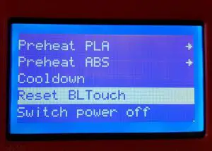
- Some printer manufactures have added Reset BLTouch to the LCD menu