Dishwasher
SMS2HKW66G [en] User manual
en
Table of contents
Safety ……………………………………….. 4 General information…………………….. 4 Intended use………………………………. 4 Restriction on user group…………….. 4 Safe installation ………………………….. 4 Safe use ……………………………………. 6 Damaged appliance ……………………. 7 Risk to children ………………………….. 8 Preventing material damage …….. 10 Safe installation ………………………… 10 Safe use ………………………………….. 10 Environmental protection and saving energy………………………….. 11 Disposing of packaging …………….. 11 Saving energy…………………………… 11 AquaSensor……………………………… 11 Installation and connection………. 11 Scope of supply ……………………….. 11 Installing and connecting the appliance …………………………………….. 12 Drainage connection …………………. 12 Drinking water connection …………. 12 Electrical connection …………………. 12 Familiarising yourself with your appliance…………………………. 14 Appliance ………………………………… 14 Controls …………………………………… 15 Programmes ……………………………. 17 Information for test institutes ………. 18 Favourite ……………………………… 18 Additional functions ………………… 19 Features………………………………….. 19 Top basket……………………………….. 19 Bottom basket ………………………….. 20 Cutlery basket ………………………….. 20 Folding prongs …………………………. 21 Baking sheet spray head …………… 21
2
Basket heights………………………….. 22 Before using for the first time …… 22 Performing the initial configuration………………………………………….. 22 Water softening system……………. 23 Overview of water hardness settings………………………………………… 23 Setting the water softening system …………………………………………. 23 Special salt ………………………………. 24 Switching off the water softening system …………………………………….. 24 Regeneration of the water softening system ………………………. 25 Rinse aid system……………………… 25 Rinse aid …………………………………. 25 Setting the amount of rinse aid …… 26 Switching the rinse aid system off …………………………………………… 26 Detergent ………………………………… 26 Suitable detergents …………………… 26 Unsuitable detergents ……………….. 28 Information on detergents ………….. 28 Adding detergent ……………………… 28 Tableware ……………………………….. 29 Damage to glass and tableware …. 29 Arrange tableware …………………….. 30 Removing tableware………………….. 31 Basic operation ……………………….. 31 Switching on the appliance ………… 31 Setting a programme ………………… 31 Setting additional functions ………… 31 Setting timer programming ………… 31 Starting the programme …………….. 32 Activating button lock………………… 32 Deactivate button lock……………….. 32 Interrupting programme …………….. 32
Terminate programme……………….. 32 Switching off appliance ……………… 32
Basic settings………………………….. 33 Overview of basic settings …………. 33 Changing basic settings…………….. 34
Home Connect ………………………… 34 Home Connect quick start …………. 35 Home Connect settings……………… 35 Remote Start ………………………. 35 Remote Diagnostics …………………. 36 Software update ……………………….. 36 Data protection…………………………. 36
Cleaning and servicing …………….. 37 Cleaning the tub ……………………….. 37 Cleaning products …………………….. 37 Tips on appliance care………………. 37 Machine Care …………………….. 37 Filter system …………………………….. 38 Cleaning spray arms …………………. 39
Troubleshooting………………………. 41 Error code / Fault display / Signal…………………………………………… 41 Washing results ………………………… 43 Home Connect problem…………….. 50 Information on display panel………. 50 Malfunctions …………………………….. 50 Mechanical damage………………….. 51 Noise ………………………………………. 52 Clean wastewater pump…………….. 53
Transportation, storage and disposal ………………………………….. 53 Removing the appliance ……………. 53 Protect appliance from frost……….. 54 Transporting the appliance ………… 54 Disposing of old appliance ………… 54
Customer Service…………………….. 54 Product number (E-Nr.), production number (FD) and consecutive numbering (Z-Nr.) ………………… 55
en Technical specifications…………… 55 Information regarding Free and Open Source Software ………………. 56 Declaration of Conformity ………….. 56
3
enSafety
Safety
Observe the following safety instructions. General information ¡ Read this instruction manual carefully. ¡ Keep the instruction manual and the product information safe
for future reference or for the next owner. ¡ Do not connect the appliance if it has been damaged in transit. Intended use Only use this appliance: ¡ For cleaning household tableware. ¡ In private households and in enclosed spaces in a domestic en-
vironment. ¡ Up to an altitude of max. 4000 m above sea level.
Restriction on user group This appliance may be used by children aged 8 or over and by people who have reduced physical, sensory or mental abilities or inadequate experience and/or knowledge, provided that they are supervised or have been instructed on how to use the appliance safely and have understood the resulting dangers. Children must not play with the appliance. Cleaning and user maintenance must not be performed by children unless they are being supervised. Keep children under the age of 8 years away from the appliance and power cable. Safe installation Follow these safety instructions when installing the appliance.
WARNING Risk of injury! Improper installation may cause injury. When installing and connecting the appliance, follow the in-
structions in the manual and installation instructions.
4
Safetyen
WARNING Risk of electric shock! Incorrect installation is dangerous. Connect and operate the appliance only in accordance with
the specifications on the rating plate. Always use the supplied power cable for the new appliance. Connect the appliance to a power supply with alternating
current only via a properly installed socket with earthing. The protective conductor system of the domestic electrical
installation must be properly installed. Never equip the appliance with an external switching
device, e.g. a timer or remote control. When the appliance is installed, the mains plug of the
power cord must be freely accessible. If free access is not possible, an all-pole isolating switch must be installed in the permanent electrical installation according to the installation regulations. When installing the appliance, check that the power cable is not trapped or damaged. WARNING Risk of fire! It is dangerous to use an extended power cord and non-approved adapters. Do not use extension cables or multiple socket strips. If the power cord is too short, contact Customer Service. Only use adapters approved by the manufacturer. WARNING Risk of burns! If the appliance is not installed properly, this may result in burns. With free-standing appliances, ensure that they are installed with the back panel against a wall.
5
enSafety
Safe use WARNING Risk of serious harm to health! Failure to comply with safety instructions and directions for use on packagings of detergent and rinse aid products may cause serious harm to health. Follow the safety instructions and directions for use on the packagings of detergent and rinse aid products. WARNING Risk of explosion!
¡ Adding solvents to the interior of the appliance may cause explosions. Never add solvents to the interior of the appliance.
¡ Highly caustic alkaline or highly acidic cleaning agents in conjunction with aluminium parts in the interior of the appliance may cause explosions. Never use highly caustic alkaline or highly acidic cleaning agents, in particular commercial or industrial products, in conjunction with aluminium parts (e.g. grease filters of extractor hoods or aluminium pans), e.g. for the Machine Care programme. WARNING Risk of injury!
¡ Leaving the appliance door open may result in injury. Only open the appliance door to load or unload tableware in order to prevent accidents, e.g. through tripping. Do not sit or stand on the appliance door when open.
¡ Knives and utensils with sharp points can cause injuries. Arrange knives and utensils with sharp points in the cutlery basket with the points downwards, on the knife shelf or in the cutlery drawer. WARNING Risk of scalding! If you open the appliance door while the programme is running, hot water may splash out of the appliance. Open the appliance door carefully if the programme is still running.
6
Safetyen
WARNING Risk of tipping! Overfilling the Baskets may cause the appliance to tip up. Never overfill the Baskets with free-standing appliances. WARNING Risk of electric shock! ¡ An ingress of moisture can cause an electric shock. Only use the appliance in enclosed spaces. Never expose the appliance to intense heat or humidity. Do not use steam- or high-pressure cleaners to clean the
appliance. ¡ If the insulation of the power cord is damaged, this is danger-
ous. Never let the power cord come into contact with hot appli-
ance parts or heat sources. Never let the power cord come into contact with sharp
points or edges. Never kink, crush or modify the power cord. Damaged appliance Follow the safety instructions if the appliance is damaged. WARNING Risk of electric shock! ¡ If the appliance or the power cord is damaged, this is dangerous. Never operate a damaged appliance. Never operate an appliance with a cracked or fractured sur-
face. Never pull on the power cord to unplug the appliance. Al-
ways unplug the appliance at the mains. If the appliance or the power cord is damaged, immediately
unplug the power cord or switch off the fuse in the fuse box and turn off the water tap. “Call Customer Service.” Page 54 Repairs to the appliance should only be carried out by trained specialist staff.
7
enSafety
¡ Incorrect repairs are dangerous. Repairs to the appliance should only be carried out by trained specialist staff. Only use genuine spare parts when repairing the appliance. If the power cord of this appliance is damaged, it must be replaced with a special connection cable, which is available from the manufacturer or his Customer Service.
Risk to children Follow the safety instructions if there are children in your home.
WARNING Risk of suffocation! ¡ Children may put packaging material over their heads or wrap
themselves up in it and suffocate. Keep packaging material away from children. Do not let children play with packaging material. ¡ Children may breathe in or swallow small parts, causing them to suffocate. Keep small parts away from children. Do not let children play with small parts. WARNING Risk of harm to health! Children can lock themselves in the appliance, thereby putting their lives at risk. With redundant appliances, unplug the power cord. Then
cut through the cord and damage the lock on the appliance door beyond repair so that the appliance door will no longer close. WARNING Risk of crushing! With higher-level appliances, children can become crushed between the appliance door and cabinet doors underneath. Keep an eye on children when opening and closing the appliance door.
8
Safetyen
WARNING Risk of chemical burns! Rinse aid and detergent may cause chemical burns to the mouth, throat and eyes. Keep children away from detergent and rinse aid products. Keep children away from the appliance when open. The wa-
ter in the interior of the dishwasher is not drinking water. It may contain residues of detergents and rinse aid. WARNING Risk of injury! Children may get their fingers caught in the slots of the tablet collecting tray and injure themselves. Keep children away from the appliance when open. WARNING Risk of suffocation! Children may become trapped in the appliance and suffocate. Use the childproof lock if fitted. Never let children play with or operate the appliance.
9
enPreventing material damage
Preventing material dam- Preventingmaterialdamage age
Preventing material damage
Safe installation
Follow the instructions when installing the appliance. ATTENTION! ¡ Improper installation of the appli-
ance may cause damage. If the dishwasher is installed
above or below other domestic appliances, follow the information on installation in combination with a dishwasher in the installation instructions for the individual appliances. If there is no information or if the installation instructions do not include the relevant information, contact the manufacturer of these appliances to check that the dishwasher can be installed above or below these appliances. If no information is available from the manufacturer, the dishwasher should not be installed above or below such appliances. To ensure the safe operation of all domestic appliances, continue following the installation instructions for the dishwasher. Do not install the dishwasher under a hob. Do not install the dishwasher near heat sources, e.g. radiators, heat storage tanks, ovens or other appliances that generate heat. ¡ Modified or damaged water hoses may result in material damage and damage to the appliance. Never kink, crush, modify or cut through water hoses. 10
Only use the water hoses supplied with the appliance or genuine spare hoses.
Never re-use water hoses that have been used before.
¡ If the water pressure is too high or too low, the appliance may not be able to operate properly. Make sure that the water pressure in the water supply system is min. 50 kPa (0.5 bar) and max. 1000 kPa (10 bar). If the water pressure exceeds the maximum value specified, a pressure-reducing valve must be installed between the drinking water connection and the hose set of the appliance.
Safe use
Follow the instructions when using the appliance. ATTENTION! ¡ Escaping water vapour can dam-
age fitted units. When the programme ends,
leave the appliance to cool down for a while before opening the door. ¡ Special salt for dishwashers can damage the tub due to corrosion. To make sure that any special salt that escapes is washed out of the tub, add the special salt to the dispenser for special salt immediately before the programme starts. ¡ Detergent may damage the water softening system. Only fill the dispenser of the water softening system with special dishwasher salt. ¡ Unsuitable cleaning agents may damage the appliance. Do not use a steam cleaner.
Environmental protection and saving energyen
So as not to scratch the finish on the appliance, do not use sponges with a rough surface or abrasive cleaning agents.
To prevent corrosion, do not use sponge cloths on dishwashers with a stainless steel front or rinse such cloths thoroughly several times before using them for the first time.
Environmental protection Environmentalprotectionandsavingenergy and saving energy
Environmental protection and saving energy
Disposing of packaging
The packaging materials are environmentally compatible and can be recycled. Sort the individual components by
type and dispose of them separately.
Saving energy
If you follow these instructions, your appliance will use less electricity and less water. Use the Eco 50 ° programme.
The Eco 50 ° programme is energy-efficient and environmentally friendly. “Programmes”, Page 17 If you do not have much tableware to wash, use the additional Half Load function.1 The programme will adjust to a lower load and consumption will be reduced. “Additional functions”, Page 19
AquaSensor
The AquaSensor is an optical measuring device (light barrier) which measures the turbidity of the rinsing water. You can save water with the AquaSensor. Use of the AquaSensor depends on the programme. If the soiling level is high, the rinsing water is drained off and replaced with fresh water. If the soiling level is lower, the rinsing water is used in the next wash cycle, so reducing water consumption by 3-6 litres. In the automatic programmes the temperature and run time are additionally adjusted to the level of soiling.
Installation and connec- Installationandconnection tion
Installation and connection
Scope of supply
After unpacking all parts, check for any damage in transit and completeness of the delivery. If you have any complaints, contact the dealer who sold you the appliance or our Customer Service. Note: The appliance has been tested at the factory to check it is in working order. It is possible that water has left marks on the appliance. These marks will disappear after the first wash cycle. The delivery consists of the following: ¡ Dishwasher ¡ Operating instructions ¡ Installation Instructions ¡ Warranty ¡ Installation material ¡ Inlet hose
1 Depending on the appliance specifications 11
enInstallation and connection
¡ Salt filling aid funnel ¡ Mains cable ¡ Quick reference guide
Installing and connecting the appliance
You can position your built-under or integrable appliance in a fitted kitchen between wooden and plastic walls. If you subsequently install your dishwasher as a free-standing appliance, you must stop it from tipping over, e.g. by screwing it to the wall or installing it under a continuous worktop that is securely connected to adjacent cabinets. 1. “Follow the safety instructions.”
Page 4 2. “Follow the instructions for elec-
trical connection.” Page 12 3. Check the Scope of supply and
the condition of the appliance. 4. Consult the installation instructions
for the installation dimensions required. 5. Make the appliance level using the height-adjustable feet. Make sure that the appliance is standing on the floor securely. 6. “Install the drainage connection.” Page 12 7. “Install the drinking water connection.” Page 12 8. Connect the appliance to the power supply.
Drainage connection
Connect your appliance to drainage connection so dirty water is discharged via the wash cycle. Installing the drainage connection 1. Consult the installation instructions
supplied for the steps required here.
12
2. Connect the wastewater hose to the outlet connection of the siphon using the enclosed parts.
3. When doing so, check that the wastewater hose is not kinked, crushed or twisted.
4. Also check that there is no cover in the drainage system preventing the wastewater from being discharged.
Drinking water connection
Connect your appliance to a drinking water connection. Installing the drinking water connection Note ¡ If you are replacing the appliance,
you must use a new water supply hose. 1. Consult the installation instructions supplied for the steps required here. 2. Connect the appliance to the drinking water connection using the enclosed parts. Observe the “Technical data” Page 55. 3. When doing so, check that the drinking water connection is not kinked, crushed or twisted.
Electrical connection
Connect your appliance to the power supply. Connecting the appliance to the electricity supply Notes ¡ Please follow the “Safety instruc-
tions” Page 4. ¡ Connect the appliance to alternat-
ing current only, in the range of 220 – 240 V and 50 Hz or 60 Hz.
¡ Please note that the water safety system is only functional if there is a power supply.
1. Insert the non-heating appliance plug of the power cable into the appliance.
2. Insert the mains plug of the appliance into a nearby socket. The connection data for the appliance can be found on the rating plate.
3. Check that the mains plug is inserted properly.
Installation and connectionen
13
enFamiliarising yourself with your appliance
Familiarising yourself with your appliance Familiarisingyourselfwithyourappliance
Familiarising yourself with your appliance
Appliance
You can find an overview of the parts of your appliance here.
7
8
6
9
5
4
10
3
11
2
12
1
1
Rating plate
Rating plate with “E number and FD number” Page 55. The data you need for “Customer Service” Page 54.
1 Depending on the appliance specifications
14
Familiarising yourself with your applianceen
2
Detergent dispenser
“Detergent” Page 26 is added to the detergent dispenser.
3
Bottom basket
“Bottom basket” Page 20
4
Dispenser for special salt
Add the special salt to the dispenser for special salt. “Water softening system”, Page 23
5
Lower spray arm
The lower spray arm washes the tableware in the bottom basket. If the tableware has not been washed properly, clean the spray arms. “Cleaning spray arms”, Page 39
6
Tablet collecting tray
During the wash cycle tablets automatically fall out of the detergent dispenser into the tablet collecting tray where they can fully dissolve.
7
Top basket
Top basket
8
Cutlery shelf1
Cutlery shelf
9
Upper spray arm
The upper spray arm washes the tableware in the top basket. If the tableware has not been washed properly, clean the spray arms. “Cleaning spray arms”, Page 39
10 Filter system
“Filter system” Page 38
11 Cutlery basket
“Cutlery basket” Page 20
12 Dispenser for rinse aid
Add rinse aid to the dispenser for rinse aid. “Rinse aid system”, Page 25
1 Depending on the appliance specifications
Controls
You can use the control panel to configure all functions of your appliance and to obtain information about the operating status. With some buttons you can perform different functions.
15
enFamiliarising yourself with your appliance
1 2 3 4 5 6 7 8 9 10
14 13 12 11
1
ON/OFF button and reset button
“Switching on the appliance” Page 31 “Switching off the appliance” Page 32
“Terminating the programme” Page 32
2
Programme button
“Programmes” Page 17
3
Special salt refill indicator
“Water softening system” Page 23
4
Rinse aid refill indicator
“Rinse aid system” Page 25
5
WLAN display
“Home Connect” Page 34
6
Water supply display
Display for water supply
7
Timer programming
“Setting timer programming” Page 31
8
Remote Start
“Remote Start “, Page 35
9
button
If you press
for approx. 3 seconds,
you can open the basic settings.
10 Start button
“Starting the programme” Page 32
11
Programme buttons and additional functions
“Programmes” Page 17 “Additional functions” Page 19
12 Door opener1
Opening the appliance door
13 Display
The display shows information about the remaining running time or the basic settings. You can change the basic settings via the display and the setting buttons.
14 Programmes
“Programmes” Page 17
1 Depending on the appliance specifications
16
Programmesen
Programmes Programmes
You Programmes can find an overview of the programmes that can be selected here. Different programmes, which can be found on the control panel of your appliance, are available depending on the appliance configuration. The running time may vary depending on the programme selected. The running time depends on the water temperature, the quantity of tableware, the level of soiling and the additional function selected. The run-
ning time will change if the rinse aid system is switched off or rinse aid needs to be added. The consumption values can be found in the quick reference guide. The consumption values relate to normal conditions and a water hardness of 16 – 20 °E. Different influencing factors such as water temperature or pipe pressure may result in deviations.
Programme Intensive 70°
Auto 45-65° Eco 50°
Use
Programme sequence Additional func-
tions
Tableware:
Intensive:
¡ Washing pots and pans, ¡ Pre-Rinse
non-fragile tableware and ¡ Cleaning 70 °C
cutlery.
¡ Intermediate rinse
Level of soiling:
¡ Final rinse 69 °C
¡ Removing stubborn burned or dried-on food
¡ Drying
remnants containing
starch and protein.
All “Additional functions”, Page 19
Tableware:
Sensor-controlled:
All
¡ Cleaning mixed table- ¡ Optimised by sensors de- “Additional
ware and cutlery.
pending on the soiling of functions”,
Level of soiling:
the rinsing water.
Page 19
¡ Removing common
household food remnants
lightly dried-on.
Tableware:
Most economical pro-
¡ Cleaning mixed table- gramme:
ware and cutlery.
¡ Pre-Rinse
Level of soiling:
¡ Cleaning 50 °C
¡ Removing common
¡ Intermediate rinse
household food remnants ¡ Final rinse 61 °C
lightly dried-on.
¡ Drying
All “Additional functions”, Page 19
17
enProgrammes
Programme
Use
Programme sequence
Silence 50°
Express 65° – 1h
Machine Care Favourite
Tableware:
Reduced noise:
¡ Cleaning mixed table- ¡ Pre-Rinse
ware and cutlery.
¡ Cleaning 50 °C
Level of soiling:
¡ Intermediate rinse
¡ Removing common
¡ Final rinse 63 °C
household food remnants lightly dried-on.
¡
Drying
Tableware:
Time-optimised:
¡ Cleaning mixed table- ¡ Cleaning 65 °C
ware and cutlery.
¡ Intermediate rinse
Level of soiling:
¡ Final rinse 69 °C
¡
Removing common household food remnants
¡
Drying
lightly dried-on.
Only when using unloaded Machine Care 70 °C appliance.
–
–
Additional functions All “Additional functions”, Page 19
Extra Dry “Additional functions”, Page 19
None –
Note: The relatively long running time in the Eco 50 ° programme is due to longer soaking and drying times. This results in optimal consumption values.
Information for test institutes
Test institutes are provided with information for comparability tests, e.g. according to EN60436. These are the conditions for conducting the tests, however they are not the results or consumption values. E-mail enquiries to: [email protected] The product number (E-Nr.) and the production number (FD) are required here. They can be found on the rating plate on the appliance door.
Favourite
You can save a combination of a programme and an additional function to the button. You can save the programme via the Home Connect app. The pre-rinse program is saved to this button at the factory. Pre-rinse is suitable for all types of tableware. The tableware undergoes intermediate cleaning via cold rinsing. When programmes have been downloaded and on delivery of the appliance, the name of the programme will be displayed in the app. The display alternately shows “APP” and the remaining running time. Tip: You can use the Home Connect app to download additional programmes and save them to the button.1
1 Depending on the appliance specifications 18
Additional functions Additionalfunctions
You can find an overview of the addi- Additionalfunctions tional functions that can be selected here. Different additional functions, which can be found on the control panel of your appliance, are available depending on the appliance configuration.
Additional func- Use tion
SpeedPerfect+
¡ The run time is shortened by 15% to 75% depending on the rinse programme.
¡ The additional function can be activated before the start of the programme and at any time when the programme is running.
¡ Energy and water consumption are increased.
Half Load
¡ Switch on with small loads.
¡ It is recommended adding less detergent to the detergent dispenser than for a full machine load.
¡ The run time is shortened.
¡ Energy and water consumption are reduced.
Extra Dry
¡ For a better drying result the final rinse temperature is increased and the drying phase extended.
¡ Especially suitable for drying plastic parts.
¡ There is a slight increase in energy consumption and the run time is extended.
Additional functionsen
Features Features
You Features can find an overview of the possible features of your appliance and how to use them here. These features depend on the model of your appliance.
Top basket
Arrange cups and glasses in the top basket.
You can adjust the height of the top basket to make room for larger items of tableware. Adjusting top basket with pairs of rollers To wash large items of tableware in the baskets, adjust the shelf position of the top basket. 1. Pull out the top basket. 2. Remove the basket.
19
enFeatures 3. Re-attach the basket to the upper
rollers (setting 3) or lower rollers (setting 1). “Basket heights”, Page 22
Check that the basket is level on both sides. 4. Slide the basket back in.
Bottom basket
Arrange pans and plates in the bottom basket.
Cutlery basket
Arrange cutlery in the cutlery basket, always without sorting it and with the sharp points downwards.
a
Cutlery basket 1 Large plates up to a diameter of 31 cm can be arranged in the bottom basket as shown.
1 Depending on the appliance specifications 20
Folding prongs
Use the folding prongs to position tableware securely, e.g. plates.
Featuresen
Baking sheet spray head
Use the baking sheet spray head to clean large items of tableware, e.g. trays, grilles and plates.
You can fold the prongs down to position pans, bowls and glasses better.1
Folding down prongs1 If you do not need the prongs, fold them down. 1. Push the lever forwards and fold
down the prongs .
1
2
Arrange max. 2 baking sheets and 2 grilles as shown to ensure that the spray jet can reach all parts. Note: Check that the appliance is always operated with the top basket or the baking sheet spray head.
Inserting baking sheet spray head Use the baking sheet spray head instead of the top basket to clean large trays, grilles and plates. 1. Remove top basket.
2. To use the prongs again, fold them back up.
a The prongs audibly click into position.
1 Depending on the appliance specifications 21
enBefore using for the first time 2. Insert the baking sheet spray head
in the holder and turn to the right .
Removing baking sheet spray head If you no longer require the baking sheet spray head, remove it from the appliance.
1. Turn the baking sheet spray head anticlockwise and remove from the holder.
2. Insert the top basket in the appliance.
a The baking sheet spray head clicks into position.
Basket heights
Set the baskets at the right height.
Appliance height 81.5 cm with cutlery basket
Setting 1 max. ø 2 max. ø 3 max. ø
Top basket 22 cm 24.5 cm 27 cm
Bottom basket 31 cm 27.5 cm 25 cm
Before using for the Beforeusingforthefirsttime first time
Configure the settings for initial start- Beforeusingforthefirsttime up.
Performing the initial configuration
On initial start-up or after a reset to the factory settings, you will need to make settings. Tip: Connect your appliance to a mobile device. You can conveniently change all settings via the
Home Connect app. “Home Connect quick start”, Page 35 Requirement: “The appliance has been installed and connected.” Page 11 1. “Add special salt.” Page 24 2. “Add rinse aid.” Page 25 3. “Switch on the appliance.”
Page 31 4. “Setting the water softening sys-
tem.” Page 23 5. “Set the amount of rinse aid to be
dispensed.” Page 26 6. “Add detergent” Page 26.
22
Water softening systemen
7. Start the Programme with the highest cleaning temperature without tableware. To remove any marks from water or other residues, we recommend you operate the appliance without tableware before using it for the first time.
Tip: You can change these settings and other “Basic settings” Page 33 at any time.
Water softening system Watersofteningsystem
Hard water leaves limescale on the Watersofteningsystem tableware as well as the washing tank and parts of the appliance may become blocked. To ensure good dishwashing results, you can treat the water with special salt and the water softening system. To avoid damage to the appliance, water with a hardness above 9 °E must be softened.
Overview of water hardness settings
You can find an overview of the water hardness values that can be selected here. You can find out how hard your water is from your local water company or by using a water hardness tester.
Water hardness °E 0 – 8 9 – 10 11 – 12 13 – 15 16 – 20 21 – 26 27 – 38 39 – 62
Hardness range Soft Soft Medium Medium Medium Hard Hard Hard
mmol/l 0 – 1.1 1.2 – 1.4 1.5 – 1.8 1.9 – 2.1 2.2 – 2.9 3.0 – 3.7 3.8 – 5.4 5.5 – 8.9
Setting value H00 H01 H02 H03 H04 H05 H06 H07
Note: Set the water hardness determined on your appliance. “Setting the water softening system”, Page 23 With a water hardness of 0 – 8 °E you can dispense with special salt for dishwashers and switch off the water softening system. “Switching off the water softening system”, Page 24
Setting the water softening system
Set the water hardness on your appliance. 1. Determine the water hardness and
the appropriate setting value. “Overview of water hardness settings”, Page 23 2. Press . 3. To open the basic settings, press
for 3 seconds. a The display shows Hxx. a The display shows .
23
enWater softening system
4. Press
repeatedly until the
right water hardness has been set.
The value H04 is set at the factory.
5. To save the settings, press for 3 seconds.
Special salt
You can use special salt to soften water. Adding special salt If the special salt refill indicator lights up, add special salt to the dispenser for special salt just before the programme starts. The amount of special salt required depends on the water hardness: the higher the water hardness, the greater the amount of special salt required.
ATTENTION! ¡ Detergent may damage the water
softening system. Only fill the dispenser of the wa-
ter softening system with special dishwasher salt. ¡ Special salt for dishwashers can damage the tub due to corrosion. To make sure that any special salt that escapes is washed out of the tub, add the special salt to the dispenser for special salt immediately before the programme starts.
1. Unscrew the lid of the dispenser for special salt and remove.
2. On initial start-up: Fill the dispenser right up with water.
3. Note: Only use special salt for dishwashers. Do not use salt tablets. Do not use table salt. Add the special salt to the dispenser.
a
Funnel 1 Fill the dispenser right up with special salt. The water in the dispenser is displaced and forced out. 4. Place the lid back on the dispenser and turn to close.
Switching off the water softening system
If you find the special salt refill indicator irritating, e.g. when using combined detergents with salt replacement substances, you can switch the salt refill indicator off. Note To avoid damage to the appliance, only switch off the water softening system in the following cases: ¡ The water hardness is max. 26 °E
and you are using combined detergents with salt replacement substances. According to manufacturers, combined detergents with salt replacement substances can gen-
1 Depending on the appliance specifications 24
erally only be used up to a water hardness of 26 °E without adding special salt. ¡ The water hardness is 0 – 8 °E. You do not need to use special salt.
1. Press .
2. To open the basic settings, press for 3 seconds.
a The display shows Hxx. a The display shows .
3. Press
repeatedly until the dis-
play shows H00.
4. To save the settings, press for 3 seconds.
a The water softening system is switched off and the salt refill indic-
ator is deactivated.
Regeneration of the water softening system
In order to obtain fault-free function of the water softening system, the appliance performs regeneration of the water softening system at regular intervals. Regeneration of the water softening system takes place before the end of the main rinse cycle in all programmes. It will increase the run time and consumption values, e.g. water and electricity.
Overview of consumption values with regeneration the water softening system Here you can find an overview of the maximum additional run time and consumption values during regeneration of the water softening system.
Regeneration of the water softening 6 system after x rinse cycles
Additional run time in minutes
7
Additional water consumption in 5 litres
Rinse aid systemen Additional power consumption in 0.05 kWh The consumption values specified are laboratory measurements determined in accordance with the currently applicable standard and using the Eco 50° programme and the factory value of the water hardness is set to 16 – 20°E.
Rinse aid system Rinseaidsystem
You can use the rinse aid system Rinseaidsystem and rinse aid to get tableware and glasses rinsed perfectly without marks.
Rinse aid
For optimum drying results, use rinse aid. Only use rinse aid for domestic dishwashers. Adding rinse aid If the rinse aid refill indicator lights up, top up with rinse aid. Only use rinse aid for domestic dishwashers. 1. Press the catch on the lid of the
dispenser for rinse aid and lift .
2
1
25
enDetergent 2. Add rinse aid up to the max mark.
max
3. If rinse aid spills out, remove it from the tub. Spilled rinse aid can cause excessive frothing during the wash cycle.
4. Close the lid of the dispenser for rinse aid.
a The lid clicks into position.
Setting the amount of rinse aid
If there are streaks or water marks on tableware, change the amount of rinse aid.
1. Press .
2. To open the basic settings, press for 3 seconds.
a The display shows Hxx. a The display shows .
3. Press
repeatedly until
the display shows the value set at
the factory r05.
4. Press
repeatedly until the
right amount of rinse aid has been
set.
A low setting adds less rinse aid during the wash cycle and reduces streaking on tableware.
A higher setting adds more rinse aid during the wash cycle, reduces water marks and improves the drying result.
5. To save the settings, press for 3 seconds.
Switching the rinse aid system off
If you find the rinse aid refill indicator irritating, e.g. when using combined detergents with a rinse aid component, you can switch the rinse aid system off.
Tip: The function of rinse aid is limited with combined detergents. You will generally get better results using rinse aid.
1. Press .
2. To open the basic settings, press for 3 seconds.
a The display shows Hxx. a The display shows .
3. Press
repeatedly until
the display shows the value set at
the factory r05.
4. Press
repeatedly until the dis-
play shows r00.
5. To save the settings, press for 3 seconds.
a The rinse aid system is switched off and the rinse aid refill indicator is deactivated.
Detergent Detergent
Find Detergent out which detergents are suitable for your appliance.
Suitable detergents
Only use detergents that are suitable for dishwashers. Both separate and combined detergents are suitable. For optimum washing and drying results, use separate detergent, adding “Special salt” Page 24 and “Rinse aid” Page 25 separately.
26
Modern, powerful detergents mainly use a low-alkaline formulation with enzymes. Enzymes break down starch and remove protein. Oxygenbased bleaching agents are generally used to remove coloured marks, e.g. tea or ketchup. Note: Follow the manufacturer’s instructions for each detergent.
Detergent Tabs
Powder detergent Liquid detergent
Description Tabs are suitable for all cleaning functions and do not need to be measured out. With shorter “Programmes” Page 17 tabs sometimes do not dissolve entirely and leave residues of detergent. This may impair the cleaning effect. Powder detergent is recommended for shorter “Programmes” Page 17. The dosage can be adjusted to the level of soiling. Liquid detergent works faster and is recommended for shorter “Programmes” Page 17 without PreRinse. Sometimes liquid detergent may leak out despite the detergent dispenser being closed. This is not a fault and is non-critical if you remember the following: ¡ Only choose a pro-
gramme without PreRinse. ¡ Do not select timer programming for starting the programme.
The dosage can be adjusted to the level of soiling.
Detergenten
Tip: Suitable detergents are available online via our website or from “Customer Service” Page 54.
Separate detergents Separate detergents are products that do not contain components other than detergent, e.g. powder detergent or liquid detergent. With powder and liquid detergent the dosage can be individually adjusted to the level of soiling of the tableware. For better washing and drying results and to avoid damage to the appliance, please additionally use “Special salt” Page 24 and “Rinse aid” Page 25.
Combined detergent Besides conventional separate detergents, a number of products are available with additional functions. These products contain not only detergent but also rinse aid and salt replacement substances (3in1) and, depending on the combination (4in1, 5in1, …), additional components such as glass protection or stainless steel cleaner. According to manufacturers, combined detergents generally only function up to a water hardness of 26 °E. With a water hardness above 26 °E you will need to add special salt and rinse aid. For the best washing and drying results we recommend using special salt and rinse aid from a water hardness of 17 °E. If you are using combined detergent, the washing programme is adjusted automatically to ensure the best possible washing and drying result.
27
enDetergent
Unsuitable detergents
Do not use detergent which could cause damage to the appliance or present a risk to health.
Detergent
Description
Hand washing-up Hand washing-up liquid
liquid
can cause increased froth-
ing and damage the appli-
ance.
Detergent containing chlorine
Chlorine residue on tableware may present a risk to health.
Information on detergents
Follow the instructions on detergents in everyday use. ¡ Detergents marked as “organic” or
“ecological” (environmentally friendly) generally contain lower levels of active agents or completely dispense with certain substances. The cleaning effect may be restricted here. ¡ Set the rinse aid and the water softening system to the separate detergent or combined detergent in use. ¡ According to manufacturers, combined detergents with salt replacement substances can only be used up to a certain water hardness, usually 26 °E, without adding special salt. For the best washing and drying results we recommend using special salt from a water hardness of 17 °E. ¡ To prevent sticking, only touch detergents in a water-soluble pouch with dry hands and only ever place them in a dry detergent dispenser. ¡ Even if the rinse aid and special salt refill indicators light up, washing programmes will run properly with combined detergents.
¡ The function of rinse aid is limited with combined detergents. You will generally get better results using rinse aid.
¡ Use tablets with a special drying performance.
Adding detergent
1. To open the detergent dispenser, press the locking latch.
2. Add the detergent to the dry detergent dispenser.
50 ml 25 ml 15 ml
If you are using tablets, one is enough. Insert the tablets in a horizontal position. If you are using powder or liquid detergent, follow the manufacturer’s instructions and quantities for dosage in the detergent dispenser. 20 ml 25 ml detergent is sufficient for normal soiling. If tableware is only lightly soiled, slightly less than the amount of detergent specified is usually sufficient.
28
3. Close the lid of the detergent dispenser.
a The lid clicks into position. a The detergent dispenser will open
automatically at the optimum time during the programme. Powder or liquid detergent will spread around the washing tank and dissolve there. Tablets will fall into the tablet collecting tray and dissolve in the right dosage. In order to ensure that tablets can dissolve evenly, do not place any other objects in the tablet collecting tray. Tip: If you use powder detergent and select a program with pre-rinse, you can also add a little detergent to the interior door of the appliance.
Tableware Tableware
Only Tableware clean tableware that is suitable for dishwashers. Note: Decorated glassware and parts made of aluminium or silver may fade or discolour with dishwashing. Delicate types of glass may turn cloudy after a few washing cycles.
Tablewareen
Damage to glass and tableware
Avoid damage to glass and tableware.
Cause
Recommendation
The following table- Only put tableware in
ware is not dish-
the dishwasher if it is
washer-safe:
marked as dish-
¡ Items of cutlery washer-safe by the
and tableware manufacturer.
made from wood
¡ Decorated glass-
ware, antique and
hand-crafted table-
ware
¡ Plastic parts not
resistant to heat
¡ Tableware made
from copper or tin
¡ Tableware soiled
with ash, wax, lub-
ricating grease or
paint
¡ Very small items of
tableware
Glass and tableware was not dishwashersafe.
Only put glasses and china in the dishwasher if it is marked as dishwasher-safe by the manufacturer.
The chemical composition of the detergent causes damage.
Use a detergent marked as gentle on tableware by the manufacturer.
Highly caustic alkaline If you are using highly
or highly acidic clean- caustic alkaline or
ing agents, in particu- highly acidic cleaning
lar commercial or in- agents, in particular
dustrial cleaning
commercial or indus-
agents, are not suit- trial cleaning agents,
able for dishwashers do not put aluminium
in conjunction with parts in the dish-
aluminium.
washer interior.
29
enTableware
Cause
Recommendation
The water temperat- Select a programme
ure of the programme with lower temperat-
is too high.
ures.
After the programme
has ended, take glass-
ware and cutlery out
of the appliance
without delay.
Arrange tableware
Arrange tableware correctly to optimise the dishwashing result and prevent damage to both the appliance and tableware. Tips ¡ Using the appliance allows you to
save energy and water compared to washing-up by hand. ¡ See our website for examples of how to load your appliance efficiently, free of charge. ¡ To save energy and water, load the machine with the number of place settings specified. “Technical specifications”, Page 55 ¡ For better washing and drying results, position items with curves or recesses at an angle so water can run off.
To save resources, do not prerinse tableware under running water. 2. Observe the following when arranging tableware: Put heavily soiled tableware in
the bottom basket, e.g. pans. The more powerful the spray jet, the better the dishwashing result will be. To prevent damage to tableware, arrange it so it is stable and cannot tip over. To prevent injury, arrange cutlery with the points and sharp edges facing down. Position containers with the openings facing down so no water can collect in them. Do not block the spray arms make sure that they can turn freely. Do not place small parts in the tablet collecting tray and do not block it with tableware so as not to obstruct the lid of the detergent dispenser.
1. Remove large remnants of food from your tableware.
30
Removing tableware
WARNING Risk of injury! Hot tableware can cause burns to the skin. When hot, tableware is sensitive to shock, may crack and can result in injury. When the programme has ended,
do not empty the appliance until the tableware has cooled down for a while. 1. To prevent water dripping on the tableware, unload it starting at the bottom and working up. 2. Check the washing tank and accessories for soiling and clean if necessary. “Cleaning and servicing”, Page 37
Basic operation Basicoperation
Basic operation
Switching on the appliance
Press . The Eco 50° programme is set by default. The Eco 50° programme is an especially environmentally friendly programme and ideal for normally soiled tableware. It is the most efficient programme for the combination of energy/water consumption for this type of tableware and evidences conformity with the EU Ecodesign Directive. If you do not perform any actions on the appliance for 10 minutes, the appliance will automatically switch off.
Basic operationen
Setting a programme
To adjust the wash cycle to the soiling level of the tableware, select a suitable programme. Press the programme button re-
peatedly until the right programme has been selected. “Programmes”, Page 17 a The programme is set and the LED flashes. a The remaining running time of the programme appears on the display.
Setting additional functions
You can set additional functions to complete the washing programme selected. Note: The additional functions which can be used depend on the programme selected. “Programmes”, Page 17 Press the button for the relevant
additional function. “Additional functions”, Page 19 a The additional function is set and the additional function button flashes.
Setting timer programming
You can delay the start of the programme by up to 24 hours. 1. Press . a “h:01” appears in the display. 2. Use to set the required start
time for the programme. 3. Press . a This activates timer programming. Tip: To deactivate timer programming, press repeatedly until “h:00” appears in the display.
31
enBasic operation
Starting the programme
Press . a The programme has ended when
the display shows “0h:00m”. Notes ¡ If you want to add more tableware
while the appliance is running, do not use the tablet collecting tray as a handle for the top basket. You might touch the partially dissolved tablet. ¡ You can only change a programme when running if you cancel it. “Terminate programme”, Page 32 ¡ The appliance switches off automatically 1 minute after the end of the programme to save energy. If you open the appliance door immediately after the programme has ended, the appliance will switch off after 4 seconds.
Activating button lock
The button lock prevents the appliance from being operated accidentally or incorrectly while running. Press for approx. 3 seconds. a The button lock is activated and
will be automatically deactivated at the end of the programme. a When the appliance is operated,
flashes on the display. a The button lock remains activated
with a power failure.
Deactivate button lock
Press for approx. 3 seconds.
Interrupting programme
Note: When you open the appliance door once the appliance has heated up, leave the door slightly ajar for a
32
few minutes and then close it. This will help prevent excess pressure building up in the appliance and stop the appliance door bursting open. 1. Press . a The programme is saved and the
appliance switches off. 2. Press to resume the pro-
gramme.
Terminate programme
To end a programme early or to switch from a programme that has already started, you will need to cancel it first.
Press
for approx.
4 seconds.
a All displays light up.
a As soon as the displays are off,
the display shows “0h:01m” and
the residual water is pumped out.
a The programme is cancelled and
ends after approx. 1 minute.
Switching off appliance
1. Please note the information on “Safe use” Page 10.
2. Press . 3. To prevent damage from dripping
water, turn the water tap off tight (not applicable to appliances with Aqua-Stop). Tip: If you press during the wash cycle, the programme currently running will be interrupted. When you switch the appliance back on, the programme continues automatically.
Basic settingsen
Basic settings Basicsettings
You Basicsettings can configure the appliance to meet your needs.
Overview of basic settings
The basic settings depend on the features of your appliance.
Basic setting Water hardness
Display text Selection
H04 1
H00 – H07
Rinse aid dispensing r05 1
r00 – r06
Intensive drying
d00 1
d00 – d01
Hot water
A00 1
A00 – A01
1 Factory setting (may vary according to model)
Description Set the water softening system to your water hardness. “Setting the water softening system”, Page 23 Level H00 switches the water softening system off.
Set the amount of rinse aid to be dispensed. “Setting the amount of rinse aid”, Page 26 Switch the rinse aid system off with level r00.
The temperature is increased during the final rinse, which improves the drying result. This may increase the run time slightly. Note: Not suitable for delicate items of tableware. Switch Extra Dry on “d01” or off “d00”.
Set cold water or hot water connection. Only set the appliance to hot water if this can be prepared with little energy and a suitable installation is available, e.g. solar heating system with circulation line. The water temperature should be at least 40 °C and max. 60 °C. Switch hot water on “A01” or off “A00”.
33
enHome Connect
Basic setting Wi-Fi
Display text Selection
Cn0
Cn0 – Cn1
Remote Start
rc1
rc0 – rc2
Factory setting
rE
Start with YES Confirm with
1 Factory setting (may vary according to model)
Description Switch the wireless network connection on or off. Level “Cn0” switches the wireless network connection off. The basic setting “Wi-Fi” is only available once the appliance is connected to the Home Connect app. “Home Connect “, Page 34 Activate or deactivate “Remote Start “, Page 35. The following settings are possible: ¡ With the setting “rc0”, the func-
tion is permanently deactivated. ¡ With the setting “rc1”, the func-
tion can be selected via the button. “Activating Remote Start “, Page 36 ¡ With the setting “rc2”, the function is permanently activated. This basic setting is not available until after you have connected the device with the Home Connect app. “Home Connect “, Page 34 Restore changed settings to the factory settings. The settings for initial start-up must be configured.
Changing basic settings
1. Press .
2. To open the basic settings, press for 3 seconds.
a The display shows Hxx. a The display shows .
3. Press
repeatedly until
the display shows the required set-
ting.
4. Press
repeatedly until the dis-
play shows the right value.
You can change several settings.
5. To save the settings, press for 3 seconds.
34
Home Connect HomeConnect
This HomeConnect appliance is network-capable. Connect your appliance to a mobile device to control its functions via the Home Connect app. The Home Connect services are not available in every country. The availability of the Home Connect function depends on the availability of Home Connect services in your country. You can find information about this at: www.home-connect.com.
To be able to use Home Connect, you must first set up the connection to the WLAN home network (Wi-Fi1) and to the Home Connect app. ¡ “Connecting the appliance to
WLAN home network (Wi-Fi)”, Page 35 The Home Connect app guides you through the entire login process. Follow the instructions in the Home Connect app to configure the settings. Tips ¡ Please consult the documents supplied by Home Connect. ¡ Please also follow the instructions in the Home Connect app. Note: Please note the safety precautions in this instruction manual and make sure that they are also observed when operating the appliance via the Home Connect app. “Safety”, Page 4
Home Connect quick start
Connect your appliance to a mobile device quickly and easily. Installing app 1. Install the Home Connect app on
your mobile device.
2. Start the app and set up access for Home Connect. The Home Connect app guides you through the entire login process.
Home Connect en Connecting the appliance to WLAN home network (Wi-Fi) Requirements ¡ Home Connect app is installed on
your mobile device. ¡ Wi-Fi on the router is activated. ¡ The appliance receives signals
from the WLAN home network (WiFi) at its installation location. 1. With the help of the Home Connect App scan the QR code.
2. Follow the instructions in the Home Connect app.
Home Connect settings
Adapt Home Connect to your needs. You can find the Home Connect settings in the basic settings for your appliance. Which settings the display shows will depend on whether Home Connect has been set up and whether the appliance is connected to your home network.
Remote Start
You can use the Home Connect app to start the appliance with your mobile device. Tip: If you select “rc2” in the “Basic settings” Page 34 of this function, the function is permanently activated and you can start your appliance with a mobile device at any time.
1 Wi-Fi is a registered trademark of the Wi-Fi Alliance. 35
enHome Connect
Activating Remote Start When you have selected “rc1” in the basic settings of this function, activate the function on your appliance. Requirements ¡ The appliance is connected to your
WLAN home network. ¡ The appliance is connected to the
Home Connect app. ¡ “rc1” is selected in the “Basic set-
tings ” Page 34 of this function. ¡ A programme is selected. Press .
If you open the appliance door, the function is automatically deactivated. a button lights up. Tip: To deactivate the function, press .
Remote Diagnostics
Customer Service can use Remote Diagnostics to access your appliance if you contact them, have your appliance connected to the Home Connect server and if Remote Diagnostics is available in the country in which you are using the appliance. Tip: For further information and details about the availability of Remote Diagnostics in your country, please visit the service/support section of your local website: www.home-connect.com
Software update
You can use this function to update the software of your appliance, e.g. for optimisation, troubleshooting or safety-relevant updating. The Home Connect app informs you about available software updates.
Data protection
Please see the information on data protection. The first time your appliance is registered on a home network connected to the Internet, your appliance will transmit the following types of data to the Home Connect server (initial registration): ¡ Unique appliance identification
(consisting of appliance codes as well as the MAC address of the Wi-Fi communication module installed). ¡ Security certificate of the Wi-Fi communication module (to ensure a secure data connection). ¡ The current software and hardware version of your appliance. ¡ Status of any previous reset to factory settings. This initial registration prepares the Home Connect functions for use and is only required when you want to use the Home Connect functions for the first time. Note: Please note that the Home Connect functions can only be utilised with the Home Connect app. Information on data protection can be retrieved in the Home Connect app.
36
Cleaning and servicingen
Cleaning and servicing Cleaningandservicing
To keep your appliance working effi- Cleaningandservicing ciently for a long time, it is important to clean and maintain it carefully.
Cleaning the tub
WARNING Risk of harm to health! Using detergents containing chlorine may result in harm to health. Never use detergents containing
chlorine. 1. Remove any coarse soiling in the
interior with a damp cloth. 2. Add detergent to the detergent dis-
penser. 3. Select the programme with the
highest temperature. “Programmes”, Page 17 4. “Start the programme without tableware.” Page 32
Cleaning products
Only use suitable cleaning products to clean your appliance. “Safe use”, Page 10
Tips on appliance care
Follow the tips on appliance care to make sure your appliance functions properly at all times.
Action
Benefit
Wipe the door seals, This ensures the parts the front of the dish- of the appliance will washer and the con- remain clean and hytrol panel regularly us- gienic. ing a damp cloth and washing-up liquid.
If the appliance is not This will prevent ungoing to be used for a pleasant odours. while, leave the door slightly ajar.
Machine Care
Deposits, e.g. from remnants of food and limescale, can cause your appliance to malfunction. To avoid such faults and reduce odours, we recommend cleaning your appliance at regular intervals. Machine Care combined with machine care products and machine cleaners is the right programme for the care of your appliance.
Tip: You can get our tested and approved Dishwasher Care and Machine Cleaner for Dishwashers online at https://www.bosch-home.com/ store or from customer service. Machine Care is a programme which removes various deposits in one washing cycle. Cleaning takes place in two phases:
Phase 1
2
Removal of Grease and limescale
Food remnants and deposits
Detergent
Placement
Liquid machine care product Appliance interior, e.g. bottle
or machine descaler in
hung in the cutlery basket or
powder form.
powder in the interior.
Machine cleaner
Detergent dispenser
37
enCleaning and servicing
To ensure optimum cleaning performance, the programme doses the detergents independently of each another during the relevant cleaning phase. Correct placement of the detergents is necessary here. Run Machine Care without tableware if the indicator for Machine Care lights up on the control panel or if advised to do so by the display. The indicator will go out after you have run Machine Care. If your appliance does not have a reminder function, we recommend performing Machine Care every 2 months.
Running Machine Care Run the Machine Care programme if the indicator for Machine Care lights up on the control panel or if advised to do so by the display. Notes ¡ Run the Machine Care programme
without any tableware in the dishwasher. ¡ Only use machine care products and machine cleaners specially designed for dishwashers. ¡ Make sure that there are no aluminium parts, e.g. extractor hood grease filters or aluminium pans, in the interior of the appliance. ¡ If you have not run Machine Care after 3 washing cycles, the indicator for Machine Care will go out automatically. ¡ For optimum cleaning performance, ensure the correct placement of cleaners. ¡ Follow the safety instructions given on the packagings of the machine care products and machine cleaners. 1. Remove any coarse soiling in the interior with a damp cloth. 2. Clean the filters.
3. Place the machine care product in the appliance interior. Only use machine care products specially designed for dishwashers.
4. Pour the machine cleaner into the detergent dispenser until it is filled completely. Do not place any additional machine cleaner in the appliance interior.
5. Press . 6. Press . a Machine Care is run. a Once the programme has ended,
the indicator for Machine Care goes out.
Filter system
The filter system removes coarse soiling from the dishwashing cycle.
3
2
1
1 Micro filter 2 Fine filter 3 Coarse filter
Cleaning filters Soiling in the dishwashing water may block the filters. 1. After each wash check the filters
for residue.
38
2. Turn the coarse filter anticlockwise and remove the filter system .
Check that no foreign objects fall into the sump.
2
1
3. Pull down the micro filter to remove.
Cleaning and servicingen
Carefully clean the rim of dirt between the coarse and the fine filter. 6. Re-assemble the filter system. Make sure that the locking catches on the coarse filter click into position. 7. Insert the filter system into the appliance and turn the coarse filter clockwise. Make sure that the arrow markings match up.
Cleaning spray arms
Limescale and soiling in the dishwashing water may block the nozzles and bearings on the spray arms. Clean the spray arms regularly. 1. Unscrew the upper spray arm
and pull down to remove .
4. Press the locking catches together and lift the coarse filter out . 2 1
1
2
2. Pull up the lower spray arm to remove.
5. Clean the filter elements under running water. 39
enCleaning and servicing 3. Check the outlet nozzles on the
spray arms for blockages under running water and remove any foreign bodies. 4. Insert the lower spray arm. a The spray arm clicks into position. 5. Insert the upper spray arm and screw it firmly in place.
40
Troubleshootingen
Troubleshooting Troubleshooting
You Troubleshooting can rectify minor faults on your appliance yourself. Read the troubleshooting information before contacting after-sales service. This will avoid unnecessary costs.
WARNING Risk of electric shock! Incorrect repairs are dangerous. Repairs to the appliance should only be carried out by trained specialist
staff. Only use genuine spare parts when repairing the appliance. If the power cord of this appliance is damaged, it must be replaced with a
special connection cable, which is available from the manufacturer or his Customer Service.
Error code / Fault display / Signal
Fault
Cause
E:20-60 lights up alternately. Appliance has detected calcified heating element.
E:30-00 will light up altern- Water protection system is
ately.
activated.
E:31-00 will light up altern- Water protection system is
ately.
activated.
E:34-00 will light up altern- Water is continuously run-
ately.
ning into the appliance.
E:32-00 will light up alternately or indicator for water supply lights up.
Supply hose is kinked.
Water tap is turned off. Water tap is jammed or furred up.
The filters in the water connection of the supply or AquaStop hose are blocked.
Troubleshooting 1. Descale the appliance. 2. Operate the appliance with the wa-
ter softening system.1 1. Turn off the water tap. 2. Call “Customer Service”
Page 54. 1. Turn off the water tap. 2. Call “Customer Service”
Page 54. 1. Turn off the water tap. 2. Call “Customer Service”
Page 54. Install the supply hose without
kinks. Turn on the water tap. Turn on the water tap.
The flow rate must be at least 10 l/ min when the water supply is open. 1. Switch off the appliance. 2. Pull out the mains plug. 3. Turn off the water tap.
1 Depending on the appliance specifications 41
enTroubleshooting
Fault E:32-00 will light up alternately or indicator for water supply lights up.
Cause
Troubleshooting 4. Unscrew the water connection. 5. Remove the filter from the supply
hose
E:92-40 will light up alternately. E:61-03 will light up alternately. Water is not drained.
E:61-02 will light up alternately.
6. Clean the filter. 7. Re-insert the filter in the supply
hose. 8. Screw the water connection back
on. 9. Check the water connection for
leaks. 10. Restore the power supply. 11. Switch the appliance on.
Filters are soiled or blocked. Clean the filters. “Cleaning filters”, Page 38
Wastewater hose is blocked 1. Reposition the wastewater hose
or kinked.
without kinks.
2. Remove residues.
Siphon connection is still sealed.
Check the connection to the siphon and open if necessary.
Cover of the wastewater pump is loose.
Secure the cover of the “Wastewater pump ” Page 53 so it clicks into position.
Wastewater pump is blocked.
Clean the wastewater pump. “Clean wastewater pump”, Page 53
Cover of the wastewater pump is loose
Secure the cover of the “Wastewater pump ” Page 53 so it clicks into position.
42
Troubleshootingen
Fault E:90-01 will light up alternately.
Cause Mains voltage is too low.
A different error code ap- A technical fault is present. pears in the display window. E:01-00 to E:90-10
Troubleshooting This is not a fault on the appliance. 1. Contact an electrician. 2. Have the mains voltage and elec-
trical installation checked by an electrician.
1. Press . 2. Unplug the appliance or switch off
the fuse. 3. Wait at least 2 minutes. 4. Insert the mains plug of the appli-
ance in a socket or switch on the fuse. 5. Switch the appliance on. 6. If the problem occurs again:
Press . Turn off the water tap. Pull out the mains plug. Contact “Customer Service”
Page 54 and give the error code.
Washing results
Fault Tableware is not dry.
Cause No rinse aid used or dosage set too low.
Programme or programme option has no drying phase, or the drying phase is too brief.
Troubleshooting 1. Add “Rinse aid” Page 25. 2. Set the amount of rinse aid to be
dispensed. “Setting the amount of rinse aid”, Page 26
“Select a programme with drying, e.g. intensive, strong or ECO programme.” Page 17 Some option buttons decrease the drying result, e.g varioSpeed.
43
enTroubleshooting
Fault Tableware is not dry.
Cause
Troubleshooting
Water collects in recesses of Position tableware at an angle
the tableware or cutlery.
where possible.
Plastic tableware is not dry. Cutlery is not dry.
Appliance interior still wet after wash cycle.
The combined detergent used has a poor drying performance.
1. Use rinse aid to improve drying performance.
2. Use a different combined detergent with a better drying performance.
Extra Dry not activated to im- Activate Extra Dry. prove drying performance.
Tableware removed too early or drying process not yet ended.
1. Wait until the programme ends. 2. Only remove tableware 30 minutes
after the programme has ended.
Rinse aid used has a limited Use a name-brand rinse aid.
drying performance.
Eco products may have limited ef-
fectiveness.
Not a fault. As plastic does No remedial action possible. not store heat so well, it also does not dry as well.
Cutlery not arranged properly in the cutlery basket or cutlery drawer.
Droplets can form on the cutlery contact points. 1. “Arrange cutlery individually where
possible.” Page 30 2. Avoid points of contact.
Not a fault. The condensation drying principle causes water droplets in the tub they are indeed desirable here. The moisture in the air condenses on the inside walls, runs off and is pumped out.
No action required.
44
Troubleshootingen
Fault Remnants of food on tableware.
Detergent residue in the appliance
Cause
Troubleshooting
Tableware is placed too close together or basket is overfilled.
1. Arrange tableware with sufficient space in between. The spray jets must reach the surfaces of the tableware.
2. Avoid points of contact.
Spray arm rotation is blocked.
Arrange tableware so that it does not obstruct spray arm rotation.
Spray arm nozzles are blocked.
Clean the “Spray arms” Page 39.
Filters are soiled.
Clean the filters. “Cleaning filters”, Page 38
Filters are inserted incorrectly and/or not engaged.
1. Insert the filters properly. “Filter system”, Page 38
2. Engage the filters.
Washing programme selec- Select a more intensive washing
ted too weak.
programme.
“Programmes”, Page 17
Tableware has been pre- Only remove large remnants of food
cleaned too intensely. The
and do not prerinse tableware.
sensors chose a weaker pro-
gramme. Stubborn soiling
cannot be entirely removed.
Tall narrow receptacles in Do not position tall narrow recept-
corner areas are not rinsed acles at too great an angle or in
adequately.
corner areas.
Top baskets on right and left Set the top baskets on the left and
are not set to same height.
right to the same level.
Lid of the detergent dispenser is blocked by items of tableware parts and will not open.
1. Arrange tableware in the top basket tableware so the tab collecting tray is not obstructed by tableware. “Arrange tableware”, Page 30 Items of tableware are blocking the dispenser lid.
2. Do not place tableware or fragrance dispensers in the tablet collecting tray.
The lid of the detergent dis- Position the tab in the detergent dispenser is blocked by the tab penser crosswise, not vertically. and will not open.
45
enTroubleshooting
Fault Detergent residue in the appliance
Cause
Troubleshooting
Tabs are used in the quick Select a more intensive “Pro-
or short programme. Dissolv- gramme” Page 17 or use
ing time of the tab is not at-
“Powder detergent” Page 26.
tained.
Washing effect and dissolving performance are reduced after a prolonged storage time or detergent is very lumpy.
Change your “detergent” Page 26.
Water marks on plastic parts.
Due to laws of physics
Select a more intensive pro-
droplet formation on plastic gramme.
surfaces is unavoidable.
“Programmes”, Page 17
After drying water marks are visible.
Position tableware at an angle. “Arrange tableware”, Page 30
Use rinse aid. “Rinse aid”, Page 25
Set the water softening system higher.
Wipeable or water-soluble Detergent substances are Change your “detergent”
coatings are present inside deposited there. These coat- Page 26.
the appliance or on the door. ings cannot generally be removed with chemicals.
Clean the appliance mechanically.
White coating is deposited in 1. Set the water softening system cor-
the appliance interior.
rectly.
In most cases you will need to increase the setting.
2. Change your detergent if required.
Special salt dispenser is not Screw the special salt dispenser
screwed tight.
tight.
Stubborn white coatings are Detergent substances are Change your “detergent”
present on tableware, inside deposited there. These coat- Page 26.
the appliance or the door.
ings cannot generally be removed with chemicals.
Clean the appliance mechanically.
The hardness range is set in- Set the Water softening system to
correctly or the water hard- the water hardness or add special
ness is greater than 62 °E
salt.
(8,9 mmol/l).
3in1/organic/eco detergent Set the Water softening system to
is not effective enough.
the water hardness and use separ-
ate detergents (proprietary deter-
gent, special salt, rinse aid).
46
Troubleshootingen
Fault
Cause
Troubleshooting
Stubborn white coatings are Too little detergent is being Increase the amount of detergent
present on tableware, inside used.
used or change “Detergent ”
the appliance or the door.
Page 26.
Washing programme selec- Select a more intensive washing
ted too weak.
programme.
“Programmes”, Page 17
Tea residue or lipstick marks Washing temperature is too Select a programme with a higher
on tableware.
low.
washing temperature.
“Programmes”, Page 17
Too little detergent is being used or is unsuitable.
Use a suitable “Detergent ” Page 26 and follow the manufacturer’s instructions for the amount to be used.
Tableware has been pre- Only remove large remnants of food
cleaned too intensely. The
and do not prerinse tableware.
sensors chose a weaker pro-
gramme. Stubborn soiling
cannot be entirely removed.
Coloured coatings (blue, yel- The formation of films is due Clean the appliance.
low, brown) that are difficult or impossible to remove are present inside the appliance or on stainless steel tableware.
to substances contained in vegetables (cabbage, celery, potatoes, noodles, etc.) or tap water (manganese).
You can remove deposits with “Mechanical cleaning” Page 37 or a machine cleaning product. It may not always be possible to completely remove deposits but they
are harmless to health.
The formation of films is due Clean the appliance.
to metal components on silver or aluminium tableware.
You can remove deposits with “Mechanical cleaning” Page 37
or a machine cleaning product. It
may not always be possible to com-
pletely remove deposits but they
are harmless to health.
47
enTroubleshooting
Fault
Cause
Troubleshooting
Coloured deposits (yellow, The formation of films is due 1. Check the setting of the water
orange, brown) that are easy to ingredients of food rem-
softening system.
to remove are present inside nants and tap water (limes- 2. Add special salt.
the appliance (mainly at the cale) “soaplike”.
“Adding special salt”, Page 24
bottom).
3. If you are using combined deter-
gents (tabs), activate the water
softening system.
Follow the information about detergents. “Information on detergents”, Page 28
Plastic parts inside the appli- Plastic parts inside the appli- Discolouration can come about and
ance are discoloured.
ance may become discol-
will not impair functioning of the ap-
oured during the life of the
pliance.
dishwasher.
Plastic parts are discoloured.
Washing temperature is too Select a programme with a higher
low.
washing temperature.
“Programmes”, Page 17
Tableware has been pre- Only remove large remnants of food
cleaned too intensely. The
and do not prerinse tableware.
sensors chose a weaker pro-
gramme. Stubborn soiling
cannot be entirely removed.
Removable streaks are present on glasses, glassware with a metallic appearance and cutlery.
Amount of rinse aid to be dispensed is set too high. No rinse aid has been added.
Set the rinse aid system to a lower setting.
“Adding rinse aid”, Page 25
Detergent residue is present 1. Arrange tableware in the top basket
in the final rinse. Lid of the
tableware so the tab collecting tray
detergent dispenser is
is not obstructed by tableware.
blocked by tableware items “Arrange tableware”, Page 30
and will not open fully.
Items of tableware are blocking the
dispenser lid.
2. Do not place tableware or fragrance dispensers in the tablet col-
lecting tray.
Tableware has been pre- Only remove large remnants of food
cleaned too intensely. The
and do not prerinse tableware.
sensors chose a weaker pro-
gramme. Stubborn soiling
cannot be entirely removed.
48
Troubleshootingen
Fault Irreversible clouding of glassware.
Cause Glasses are not dishwasherproof, only suitable for dishwashers.
Troubleshooting Use dishwasher-proof glasses.
Glasses are usually only suitable for use in a dishwasher, i.e. long-term wear or long-term changes must be expected.
Avoid a lengthy steam phase (standing time after wash cycle ends).
Use a programme with a lower temperature. “Programmes”, Page 17
Set the softening system to the water hardness.
Use detergent with a glass protection component.
Rust spots on cutlery.
Cutlery is not sufficiently rust-resistant. Knife blades are often more severely affected. Cutlery may also rust if washed together with rusting items. Salt content in washing water is too high.
Use rust-resistant tableware. Do not wash rusting items. 1. Remove any spilled special salt
from the tub. 2. Screw the cap of the special salt
dispenser on tight.
Detergent residue is present Spray arms were blocked by Check that the spray arms are not in the detergent dispenser tableware so detergent was blocked and can rotate freely. or the tablet collecting tray. not rinsed out.
Excessive formation of foam occurs.
Detergent dispenser was damp when detergent was added. Hand washing-up liquid is present in dispenser for rinse aid.
Only add detergent to a detergent dispenser when dry.
Immediately add rinse aid to the dispenser. “Adding rinse aid”, Page 25
Rinse aid has been spilled. Remove the rinse aid with a cloth.
Detergent or appliance care Change the brand of detergent. product used causes excessive foaming.
49
enTroubleshooting
Home Connect problem
Fault Connection to home network is not established. WLAN display is flashing.
Home Connect cannot be implemented correctly.
Cause WLAN on router is not active. Connection to home network is not available. Home Connect set incorrectly. Technical fault is present.
Troubleshooting Check the wireless network con-
nection of your router. Activate the wireless network con-
nection on your router. Please consult the documents sup-
plied for Home Connect. Please consult the information
about support in the documents supplied for Home Connect.
Information on display panel
Fault Special salt refill indicator lights up.
Refill indicator for special salt does not light up. Refill indicator for rinse aid lights up.
Refill indicator for rinse aid does not light up. Display flashes.
Cause
Troubleshooting
Insufficient special salt.
Add “Special salt” Page 24.
Sensor does not detect spe- Do not use special salt tablets. cial salt tablets.
Water softening system is Setting the water softening system switched off.
Insufficient rinse aid.
1. Add “Rinse aid” Page 25. 2. Set the amount of rinse aid to be
dispensed. “Setting the amount of rinse aid”, Page 26
Rinse aid system is switched Set the amount of rinse aid to be
off.
dispensed.
Appliance door is not closed Close the appliance door.
properly.
Arrange the tableware so
that no parts project beyond
the basket and prevent the
appliance door from closing
properly.
Malfunctions
Fault
Cause
Water is left in the appliance Filter system or area under
at the end of the pro-
the filters is blocked.
gramme.
Troubleshooting 1. Clean the “Filters” Page 38. 2. Clean the “Wastewater pump”
Page 53.
50
Troubleshootingen
Fault
Cause
Water is left in the appliance Programme has not yet
at the end of the pro-
ended.
gramme.
Troubleshooting Wait until the programme ends or
cancel the programme with Reset.
“Terminate programme”, Page 32
Appliance cannot be switched on or operated.
Software update is taking Wait until the software update has
place.
finished.
Appliance functions have failed.
1. Pull out the mains plug or switch off the fuse.
2. Wait at least 2 minutes. 3. Connect the appliance to the power
supply. 4. Switch the appliance on.
Appliance does not start. The mains fuse has tripped. Check the relevant fuse.
Mains cable is not inserted.
1. Check whether the socket works. 2. Check whether the mains cable is
properly inserted in the socket and on the rear of the appliance.
Programme starts automatically.
Appliance door is not closed Close the appliance door. properly.
You did not wait until programme ended.
“Terminate programme”, Page 32
Appliance stops during the programme or cuts out.
Appliance door is not closed Close the appliance door. properly.
Power and/or water supply 1. Check the power supply.
has been interrupted.
2. Check the water supply.
Top basket is pressing against inner door and preventing appliance door from being closed securely.
Check whether the rear panel of the appliance is being pressed in by a socket or hose holder that has not been removed.
Arrange the tableware so that no parts project beyond the basket and prevent the appliance door from closing properly.
Mechanical damage
Fault Appliance door cannot be closed.
Cause Door lock has been activated.
Troubleshooting Close the appliance door with
greater force.
51
enTroubleshooting
Fault Appliance door cannot be closed.
Lid on the detergent dispenser cannot be closed.
Cause Door cannot be closed due to installation method.
Detergent dispenser or lid are blocked by sticky detergent residue.
Troubleshooting Check whether the appliance has
been installed properly. When closed, the appliance door, its decor or attached parts should not knock against adjacent cabinets or the worktop.
Remove detergent residue.
Noise
Fault Filling valves making knocking noises.
Knocking or rattling noise.
Cause Caused by the domestic installation. No appliance fault present. Does not affect functioning of the appliance. Spray arm is striking tableware. With a small load the water jets directly strike against the tub.
Light items of tableware move about during the wash cycle.
Troubleshooting Can only be remedied in the do-
mestic installation.
Arrange tableware so that the spray arms do not strike tableware.
Distribute the tableware evenly. Load the appliance with more table-
ware. Position light items of tableware se-
curely.
52
Clean wastewater pump
Large remnants of food or foreign bodies can block the waste water pump. As soon as the rinsing water no longer drains properly, the waste water pump must be cleaned.
WARNING Risk of injury! Sharp and pointed objects or fragments of glass may block the waste water pump and cause injury. Remove any foreign bodies care-
fully. 1. Disconnect the appliance from the
power supply. 2. Remove the top and bottom bas-
ket. 3. Remove the filter system. 4. Scoop out any water.
Use a sponge if necessary. 5. Prise off the pump cover using a
spoon and grip it by the crosspiece.
6. Lift the pump cover inwards at an angle and remove.
7. Remove any remnants of food and foreign bodies in the area of the impeller.
Transportation, storage and disposalen 8. Insert the pump cover and press
down .
2 1
a The pump cover clicks into position.
9. Install the filter system. 10.Insert the top and bottom basket.
Transportation, storage Transportation,storageanddisposal and disposal
You can find out here how to prepare Transportation,storageanddisposal your appliance for transportation and storage. You will also find out how to dispose of old appliances.
Removing the appliance
1. Disconnect the appliance from the power supply.
2. Turn off the water tap. 3. Detach the drainage connection. 4. Detach the drinking water connec-
tion. 5. Loosen any screws fastening the
appliance to cabinet parts. 6. Remove the base panel if fitted. 7. Pull the appliance out carefully,
along with the hose behind it.
53
enCustomer Service
Protect appliance from frost
If there is a risk of frost where the appliance will be standing, e.g. in a holiday home, empty the appliance completely. “Empty the appliance.”
Page 54
Transporting the appliance
To avoid damage to the appliance, empty it before transporting. Note: Always transport the dishwasher upright to prevent residual water getting into the machine’s controls and damaging the appliance. 1. Remove tableware from the appli-
ance. 2. Secure loose parts. 3. Turn on the water tap. 4. “Switch on appliance.” Page 31 5. Select the programme with the
highest temperature. “Programmes”, Page 17 6. “Start the programme.” Page 32 7. To drain the appliance, terminate the programme after approx. 4 minutes. “Terminate programme”, Page 32 8. “Switch off the appliance.” Page 32 9. Turn off the water tap. 10.To empty the residual water out of the appliance, detach the supply hose and let the water drain out.
54
Disposing of old appliance
Valuable raw materials can be reused by recycling.
WARNING Risk of harm to health! Children can lock themselves in the appliance, thereby putting their lives at risk. With redundant appliances, unplug
the power cord. Then cut through the cord and damage the lock on the appliance door beyond repair so that the appliance door will no longer close. 1. Unplug the appliance from the mains. 2. Cut through the power cord. 3. Dispose of the appliance in an environmentally friendly manner. Information about current disposal methods are available from your specialist dealer or local authority.
This appliance is labelled in accordance with European Directive 2012/19/EU concerning used electrical and electronic appliances (waste electrical and electronic equipment – WEEE). The guideline determines the framework for the return and recycling of used appliances as applicable throughout the EU.
Customer Service CustomerService
IfCustomerService you have any queries, are unable to rectify faults on the appliance yourself or if your appliance needs to be repaired, contact Customer Service. Function-relevant genuine spare parts according to the corresponding Ecodesign Order can be obtained from Customer Service for a period of at
least 10 years from the date on which your appliance was placed on the market within the European Economic Area. Note: Under the terms of the manufacturer’s warranty the use of Customer Service is free of charge. Detailed information on the warranty period and terms of warranty in your country is available from our aftersales service, your retailer or on our website. If you contact Customer Service, you will require the product number (ENr.), the production number (FD) and the consecutive numbering (Z-Nr.) of your appliance. The contact details for Customer Service can be found in the enclosed Customer Service directory or on our website.
Product number (E-Nr.), production number (FD) and consecutive numbering (Z-Nr.)
You can find the product number (ENr.), the production number (FD) and the consecutive numbering (Z-Nr.) on the appliance’s rating plate. The rating plate is located inside the appliance door. Make a note of your appliance’s details and the Customer Service telephone number to find them again quickly.
Technical specifications Technicalspecifications
Technical specifications
Weight Voltage
Max.: 60 kg 220 – 240 V, 50 Hz or 60 Hz
Technical specificationsen
Power rating Fuse Power consumption
Water pressure Inlet rate Water temperature Capacity
2000 – 2400 W 10 – 16 A Off mode/standby mode: 0.50 W Left-on mode: 0.50 W Networked standby: 2.00 W Time in left-on mode: 0 min Time after which appliance is switched to networked standby mode: 10 min Complies with the latest regulations (EU) for energy labels and ecodesign at the time of placing on the market. Additional functions and settings may increase power consumption and times. ¡ Min. 0.05 MPa
(0.5 bar) ¡ Max. 1 MPa
(10 bar) Min. 10 l/min Cold water. Hot water max.: 60 °C 12 place settings
You can find more information about your model online at https:// eprel.ec.europa.eu/1. This web address is linked to the official EU EPREL product database. Please then follow the instructions on searching for models. The model identifier is made up of the characters before the slash in the product number (E-Nr.) on the rating plate. Al-
1 Only applies to countries in the European Economic Area 55
enTechnical specifications ternatively, you can also find the model identifier in the first line of the EU energy label.
Information regarding Free and Open Source Software
This product includes software components that are licensed by the copyright holders as free software or open source software. The applicable licence information is stored on your home appliance. You can also access the applicable licence information via your Home Connect App: “Profile -> Legal information -> Licence Information”. You can download the licence information on the brand product website (search for your appliance model on the product website and check additional documents). Alternatively, you can send a request to [email protected] or to BSH Hausgeräte GmbH GmbH, Carl-Wery-Str. 34, D-81739 München, Germany. The source code will be made available to you on request.
BE
BG
CZ
DK
ES
FR
HR
IT
HU
MT
NL
AT
SK
FI
SE
UK
5 GHz WLAN (Wi-Fi): For indoor use only.
To file a request, please email to [email protected] or send a written request to BSH Hausgeräte GmbH, Carl-Wery-Str. 34, D-81739 München, Germany. Reference “OSSREQUEST” The cost of performing your request will be charged to you. This offer is valid three years from the date of purchase or at least as long as we offer support and spare parts for the respective appliance.
Declaration of Conformity
Robert Bosch Hausgeräte GmbH hereby declares that the appliance with Home Connect functionality meets the essential requirements and other relevant provisions of the Directive 2014/53/EU. A detailed RED Declaration of Conformity can be found online at www.bosch-home.com among the additional documents on the product page for your appliance.
2.4 GHz band: 100 mW max. 5 GHz band: 100 mW max.
DE
EE
IE
EL
CY
LV
LT
LU
PL
PT
RO
SI
NO
CH
TR
56
Thank you for buying a Bosch Home Appliance!
Register your new device on MyBosch now and profit directly from:
· Expert tips & tricks for your appliance · Warranty extension options · Discounts for accessories & spare-parts · Digital manual and all appliance data at hand · Easy access to Bosch Home Appliances Service
Free and easy registration also on mobile phones: www.bosch-home.com/welcome
Looking for help? You’ll find it here.
Expert advice for your Bosch home appliances, help with problems or a repair from Bosch experts. Find out everything about the many ways Bosch can support you: www.bosch-home.com/service Contact data of all countries are listed in the attached service directory.
Robert Bosch Hausgeräte GmbH Carl-Wery-Straße 34 81739 München GERMANY www.bosch-home.com
*9001638287*
9001638287 (010330) 642 E3 en
BOSCH Professional Mitre Saw
PARTs

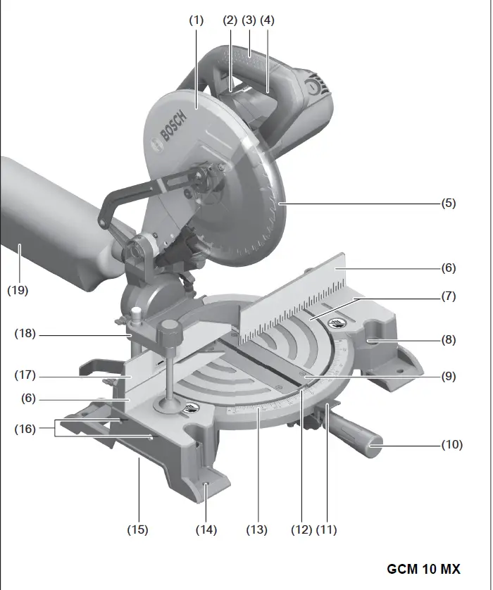
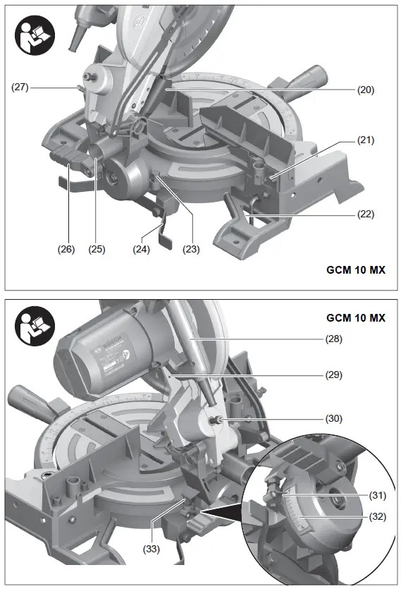
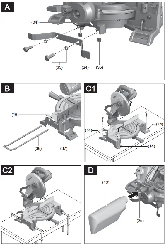
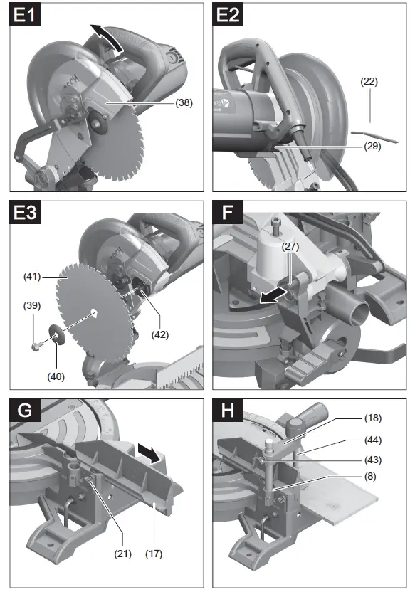
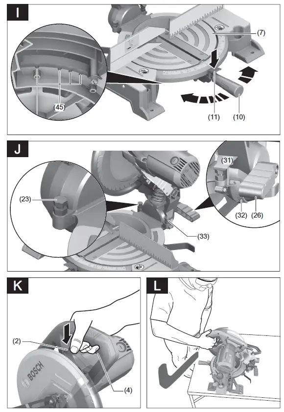
Safety instructions
WARNING: Read all safety warnings, instructions, illustrations and specifications provided with this power tool. Failure to follow all instructions listed below may result in electric shock, fire and/ or serious injury.
Save all warnings and instructions for future reference. The term “power tool” in the warnings refers to your mains operated (corded) power tool or battery-operated (cordless) power tool.
Work area safety
- Keep work area clean and well lit. Cluttered or dark areas invite accidents.
- Do not operate power tools in explosive atmospheres, such as in the presence of flammable liquids, gases or dust. Power tools create sparks which may ignite the dust or fumes.
- Keep children and bystanders away while operating a power tool. Distractions can cause you to lose control.
Electrical safety - Power tool plugs must match the outlet. Never modify the plug in any way. Do not use any adapter plugs with earthed (grounded) power tools. Unmodified plugs and matching outlets will reduce risk of electric shock.
- Avoid body contact with earthed or grounded surfaces, such as pipes, radiators, ranges and refrigerators. There is an increased risk of electric shock if your body is earthed or grounded.
- Do not expose power tools to rain or wet conditions. Water entering a power tool will increase the risk of electric shock.
- Do not abuse the cord. Never use the cord for carrying, pulling or unplugging the power tool. Keep cord away from heat, oil, sharp edges or moving parts. Damaged or entangled cords increase the risk of electric shock.
- When operating a power tool outdoors, use an extension cord suitable for outdoor use. Use of a cord suitable for outdoor use reduces the risk of electric shock.
- If operating a power tool in a damp location is unavoidable, use a residual current device (RCD) protected supply. Use of an RCD reduces the risk of electric shock.
Personal safety - Stay alert, watch what you are doing and use common sense when operating a power tool. Do not use a power tool while you are tired or under the influence of drugs, alcohol or medication. A moment of inattention while operating power tools may result in serious personal injury.
- Use personal protective equipment. Always wear eye protection. Protective equipment such as a dust mask, non-skid safety shoes, hard hat or hearing protection used for appropriate conditions will reduce personal injuries.
- Prevent unintentional starting. Ensure the switch is in the off-position before connecting to power source and/or battery pack, picking up or carrying the tool. Carrying power tools with your finger on the switch or energising power tools that have the switch on invites accidents.
- Remove any adjusting key or wrench before turning the power tool on. A wrench or a key left attached to a rotating part of the power tool may result in personal injury.
- Do not overreach. Keep proper footing and balance at all times. This enables better control of the power tool in unexpected situations.
- Dress properly. Do not wear loose clothing or jewellery. Keep your hair and clothing away from moving parts. Loose clothes, jewellery or long hair can be caught in moving parts.
- If devices are provided for the connection of dust extraction and collection facilities, ensure these are connected and properly used. Use of dust collection can reduce dust-related hazards.
- Do not let familiarity gained from frequent use of tools allow you to become complacent and ignore tool safety principles. A careless action can cause severe injury within a fraction of a second.
Power tool use and care - Do not force the power tool. Use the correct power tool for your application. The correct power tool will do the job better and safer at the rate for which it was designed.
- Do not use the power tool if the switch does not turn it on and off. Any power tool that cannot be controlled with the switch is dangerous and must be repaired.
- Disconnect the plug from the power source and/or remove the battery pack, if detachable, from the power tool before making any adjustments, changing accessories, or storing power tools. Such preventive safety measures reduce the risk of starting the power tool accidentally.
- Store idle power tools out of the reach of children and do not allow persons unfamiliar with the power tool or these instructions to operate the power tool. Power tools are dangerous in the hands of untrained users.
- Maintain power tools and accessories. Check for misalignment or binding of moving parts, breakage of parts and any other condition that may affect the power tool’s operation. If damaged, have the power tool repaired before use. Many accidents are caused by poorly maintained power tools.
- Keep cutting tools sharp and clean. Properly maintained cutting tools with sharp cutting edges are less likely to bind and are easier to control.
- Use the power tool, accessories and tool bits etc. in accordance with these instructions, taking into account the working conditions and the work to be performed. Use of the power tool for operations different from those intended could result in a hazardous situation.
- Keep handles and grasping surfaces dry, clean and free from oil and grease. Slippery handles and grasping surfaces do not allow for safe handling and control of the tool in unexpected situations.
Service - Have your power tool serviced by a qualified repair person using only identical replacement parts. This will ensure that the safety of the power tool is maintained. Safety Warnings for Mitre Saws
- Mitre saws are intended to cut wood or wood-like products, they cannot be used with abrasive cut-off wheels for cutting ferrous material such as bars, rods, studs, etc. Abrasive dust causes moving parts such as the lower guard to jam. Sparks from abrasive cutting will burn the lower guard, the kerf insert and other plastic parts.
- Use clamps to support the workpiece whenever possible. If supporting the workpiece by hand, you must always keep your hand at least 100 mm from either side of the saw blade. Do not use this saw to cut pieces that are too small to be securely clamped or held by hand. If your hand is placed too close to the saw blade, there is an increased risk of injury from blade contact.
- The workpiece must be stationary and clamped or held against both the fence and the table. Do not feed the workpiece into the blade or cut “freehand” in any way. Unrestrained or moving workpieces could be thrown at high speeds, causing injury.
- Push the saw through the workpiece. Do not pull the saw through the workpiece. To make a cut, raise the saw head and pull it out over the workpiece without cutting, start the motor, press the saw head down and push the saw through the workpiece. Cutting on the pull stroke is likely to cause the saw blade to climb on top of the workpiece and violently throw the blade assembly towards the operator.
- Never cross your hand over the intended line of cutting either in front or behind the saw blade. Supporting the workpiece “cross handed” i.e. holding the workpiece to the right of the saw blade with your left hand or vice versa is very dangerous.
- Do not reach behind the fence with either hand closer than 100 mm from either side of the saw blade, to remove wood scraps, or for any other reason while the blade is spinning. The proximity of the spinning saw blade to your hand may not be obvious and you may be seriously injured.
- Inspect your workpiece before cutting. If the workpiece is bowed or warped, clamp it with the outside bowed face toward the fence. Always make certain that there is no gap between the workpiece, fence and table along the line of the cut. Bent or warped workpieces can twist or shift and may cause binding on the spinning saw blade while cutting. There should be no nails or foreign objects in the workpiece.
- Do not use the saw until the table is clear of all tools, wood scraps, etc., except for the workpiece. Small debris or loose pieces of wood or other objects that contact the revolving blade can be thrown with high speed.
- Cut only one workpiece at a time. Stacked multiple workpieces cannot be adequately clamped or braced and may bind on the blade or shift during cutting.
- Ensure the mitre saw is mounted or placed on a level, firm work surface before use. A level and firm work surface reduces the risk of the mitre saw becoming unstable.
- Plan your work. Every time you change the bevel or mitre angle setting, make sure the adjustable fence is set correctly to support the workpiece and will not interfere with the blade or the guarding system. Without turning the tool “ON” and with no workpiece on the table, move the saw blade through a complete simulated cut to assure there will be no interference or danger of cutting the fence.
- Provide adequate support such as table extensions, saw horses, etc. for a workpiece that is wider or longer than the table top. Workpieces longer or wider than the mitre saw table can tip if not securely supported. If the cut-off piece or workpiece tips, it can lift the lower guard or be thrown by the spinning blade.
- Do not use another person as a substitute for a table extension or as additional support. Unstable support for the workpiece can cause the blade to bind or the workpiece to shift during the cutting operation pulling you and the helper into the spinning blade.
- The cut-off piece must not be jammed or pressed by any means against the spinning saw blade. If confined, i.e. using length stops, the cut-off piece could get wedged against the blade and thrown violently.
- Always use a clamp or a fixture designed to properly support round material such as rods or tubing. Rods have a tendency to roll while being cut, causing the blade to “bite” and pull the work with your hand into the blade.
- Let the blade reach full speed before contacting the workpiece. This will reduce the risk of the workpiece being thrown.
- If the workpiece or blade becomes jammed, turn the mitre saw off. Wait for all moving parts to stop and disconnect the plug from the power source and/or remove the battery pack. Then work to free the jammed material. Continued sawing with a jammed workpiece could cause loss of control or damage to the mitre saw.
- After finishing the cut, release the switch, hold the saw head down and wait for the blade to stop before removing the cut-off piece. Reaching with your hand near the coasting blade is dangerous.
- Hold the handle firmly when making an incomplete cut or when releasing the switch before the saw head is completely in the down position. The braking action of the saw may cause the saw head to be suddenly pulled downward, causing a risk of injury.
- Keep your work area clean. Material mixtures are particularly hazardous. Light metal dust may catch fire or explode.
- Do not use dull, cracked, bent or damaged saw blades. Unsharpened or improperly set saw blades produce narrow kerf causing excessive friction, blade binding and kickback.
- Do not use saw blades made from high speed steel (HSS). Such saw blades can easily break.
- Always use saw blades with correct size and shape (diamond versus round) of arbour holes. Saw blades that do not match the mounting hardware of the saw will run off-centre, causing loss of control.
- Never remove cuttings, wood chips, etc. from the cutting area while the power tool is running. Always guide the tool arm back to the neutral position first and then switch the power tool off.
- Do not touch the saw blade after working before it has cooled. The saw blade becomes very hot while working.
Products sold in GB only:
Your product is fitted with an BS 1363/A approved electric plug with internal fuse (ASTA approved to BS 1362). If the plug is not suitable for your socket outlets, it should be cut off and an appropriate plug fitted in its place by an authorised customer service agent. The replacement plug should have the same fuse rating as the original plug. The severed plug must be disposed of to avoid a possible shock hazard and should never be inserted into a mains socket elsewhere.
Symbols
The following symbols may be important for the operation of your power tool. Please take note of these symbols and their meaning. Correctly interpreting the symbols will help you to operate the power tool more effectively and safely.
Symbols and their meanings
- Keep hands away from the cutting area while the power tool is running. Contact with the saw blade can lead to injuries.
- Wear a dust mask.
- Wear safety goggles.
- Wear hearing protection. Exposure to noise can cause hearing loss.
- Danger area! Keep hands, fingers and arms away from this area.
Take note of the dimensions of the saw blade. The hole diameter must fit the tool spindle without play. If it is necessary to use reducers, ensure that the dimensions of the reducer are suitable for the base blade thickness and the saw blade hole diameter, as well as the tool spindle diameter. Wherever possible, use the reducers provided with the saw blade. The saw blade diameter must match the information specified on the symbol. When sawing bevel angles, the adjustable
fences must be pulled outwards or removed completely.
Product Description and Specifications
Read all the safety and general instructions. Failure to observe the safety and general instructions may result in electric shock, fire and/or serious injury. Please observe the illustrations at the beginning of this operating manual.
Intended Use
The power tool is intended as a stationary machine for making straight lengthways and crossways cuts. It is possible to cut mitre angles of –47° to +52° and bevel angles of 0° to 45°. The power tool is designed with sufficient capacity for sawing hardwood, softwood, chipboard and fibreboard, as well as aluminium and plastic.
Product Features
The numbering of the product features refers to the diagram of the power tool on the graphics page.
- Protective guard
- Lever for releasing the tool arm
- Handle
- On/off switch
- Retracting blade guard
- Fence
- Saw table
- Holes for screw clamp
- Insert plate
- Locking knob for all mitre angles
- Mitre presetting lever
- Angle indicator for mitre angles
- Scale for mitre angles
- Mounting holes
- Recessed handles
- Drill holes for extension bars
- Adjustable fence
- Screw clamp
- Dust bag
- Chip deflector
- Wing bolt for fixing the adjustable fence
- Hex key (6 mm)/cross-headed screwdriver
- Stop screw for 45° bevel angle
- Tilt protector
- Chip ejector
- Clamping handle for all bevel angles
- Transport safety lock
- Transport handle
- Spindle lock
- Depth stop adjusting screw
- Angle indicator for bevel angles
- Scale for bevel angles
- Stop screw for 0° bevel angle
- Holes for tilt protector
- “Tilt protector” fastening set
- Extension bar
- Fastening screw for extension bar
- Cross-head screw (retracting blade guard attachment)
- Hex socket screw for mounting the saw blade
- Clamping flange
- Saw blade
- Inner clamping flange
- Wing bolt for adjusting the height of the threaded rod
- Threaded rod
- Detents for standard mitre angles
- Screws for insert plate
- Hex socket screw for fence
- Screw for bevel angle indicator.
Technical Data
Mitre saw GCM 10 MX
Article number 3 601 M29 0..
Rated power input W 1700
No-load speed min-1 4800
Weight according to EPTA-Procedure
01:2014
kg 16.8
Protection class / II
Permitted workpiece dimensions (maximum/minimum): (see “Permissible workpiece dimensions”, page 17) The specifications apply to a rated voltage [U] of 230 V. These specifications may vary at different voltages and in country-specific models.
Dimensions of suitable saw blades
Saw blade diameter mm 254
Base blade thickness mm 1.8−2.8
Hole diameter mm 25.4
Noise Information
Noise emission values determined according to EN 62841-3-9. Typically, the A-weighted noise level of the power tool is: Sound pressure level 92 dB(A); sound power level 105 dB(A). Uncertainty K = 3 dB.
Wear hearing protection
The noise emission value given in these instructions has been measured in accordance with a standardised measuring procedure and may be used to compare power tools. It may also be used for a preliminary estimation of noise emissions. The noise emission value given represents the main applications of the power tool. However, if the power tool is used for other applications, with different application tools or is poorly maintained, the noise emission value may differ. This may significantly increase noise emissions over the total working period. To estimate noise emissions accurately, the times when the tool is switched off, or when it is running but not actually being used, should also be taken into account. This may significantly reduce noise emissions over the total working period.
Assembly
Avoid starting the power tool unintentionally. The mains plug must not be connected to the power supply during assembly or when carrying out any kind of work on the power tool.
Items included
See the list of items included at the start of the operating manual.
Check to ensure that all the parts listed below have been supplied before using the power tool for the first time:
Mitre saw with mounted saw blade
Dust bag (19)
Screw clamp (18)
Hex key/cross-headed screwdriver (22)
Tilt protector (24) with fastening set (35) (2 bolts, 2 washers, 2 square nuts)
Note: Check the power tool for possible damage. Before continuing to use the power tool, carefully check that all protective devices or slightly damaged parts are working perfectly and according to specifications. Check that the moving parts are working perfectly and without jamming; check whether any parts are damaged. All parts must be fitted correctly and all the conditions necessary to ensure smooth operation must be met. If the protective devices or any parts become damaged, you must have them properly repaired or replaced by an authorised service centre.
Fitting individual components
- Carefully remove all parts included in the delivery from their packaging.
- Remove all packing material from the power tool and the accessories provided.
Mounting the tilt protector (see figure A) - Before the power tool is used for the first time, the tilt protector (24) must be installed.
- Use the “tilt protector” fastening set (35) for the installation.
- Insert the square nuts (35) into the corresponding holes (34) in the base plate.
- Place the washers (35) on the fastening screws (35) and use them to screw the tilt protector (24) into the inserted nuts.
- Do not remove the tilt protector. Without the tilt protector, the power tool will not be stable and can tip over especially when sawing maximum mitre/bevel angles.
Fitting the extension bar (see figure B) - The free end of long and heavy workpieces must have something placed underneath it or be supported.
- To extend the saw table further, extension bars can be mounted both to the left or right of the power tool.
- Push the extension bars (36) on both sides of the power tool all the way into the corresponding drill holes (16).
- Tighten the fastening screws (37) to secure the extension bars.
Stationary or flexible mounting
- To ensure safe handling, the power tool must be mounted on a flat, stable work surface (e.g. work bench) before use.
Mounting on a work surface (see figure C1−C2) - Use suitable screw fasteners to secure the power tool to the work surface. The holes (14) are used for this purpose. or
- Firmly clamp the base of the power tool to the work surface with commercially available screw clamps.
Mounting on a Bosch saw stand - With the height-adjustable legs, Bosch GTA saw stands provide firm support for the power tool on any surface. The workpiece supports of the saw stand are used for underlaying long workpieces.
- Read all the warnings and instructions included with the saw stand. Failure to observe the warnings and follow instructions may result in electric shock, fire and/or serious injury.
- Assemble the saw stand properly before mounting the power tool. Correct assembly is important to prevent the risk of collapsing.
- Mount the power tool on the saw stand in the transport position.
Dust/Chip Extraction
The dust from materials such as lead paint, some types of wood, minerals and metal can be harmful to human health. Touching or breathing in this dust can trigger allergic reactions and/or cause respiratory illnesses in the user or in people in the near vicinity. Certain dusts, such as oak or beech dust, are classified as carcinogenic, especially in conjunction with wood treatment additives (chromate, wood preservative). Materials containing asbestos may only be machined by specialists.
- Use a dust extraction system that is suitable for the material wherever possible.
- Provide good ventilation at the workplace.
- It is advisable to wear a P2 filter class breathing mask.
- The regulations on the material being machined that apply in the country of use must be observed.
- Avoid dust accumulation at the workplace. Dust can easily ignite.
- The dust/chip extraction system can be blocked by dust, chips or fragments of the workpiece.
- Switch the power tool off and pull the mains plug out of the socket.
- Wait until the saw blade has come to a complete stop.
- Determine the cause of the blockage and eliminate it.
Self-generated dust extraction (see figure D)
For basic chip collection, use the dust bag (19) provided.
- Attach the dust bag (19) to the chip ejector (25). During sawing, the dust bag must not come into contact with moving tool components.
- Always empty the dust bag in good time
- Check and clean the dust bag each time after using.
- When sawing aluminium, remove the dust bag to avoid the risk of fire.
External Dust Extraction - You can also attach a dust extraction hose (35 mm diameter) to the chip ejector (25) for extraction.
- Connect the dust extraction hose to the chip ejector (25). The dust extractor must be suitable for the material being worked.
- When extracting dry dust that is especially detrimental to health or carcinogenic, use a special dust extractor.
Changing the saw blade (see figures E1−E3)
- Pull the plug out of the socket before carrying out any work on the power tool.
- Wear protective gloves when fitting the saw blade. There is a risk of injury when touching the saw blade. Only use saw blades that have a maximum permitted speed higher than the no-load speed of the power tool. Only use saw blades that match the specifications given in this operating manual and that have been tested and marked in accordance with EN 847-1.
- Only use saw blades that are recommended by the power tool manufacturer and are suitable for use on the material you want to saw. This will prevent the saw teeth overheating when sawing.
Removing the saw blade
- Bring the power tool into the work position.
- Push the lever (2) and swing the retracting blade guard (5) back as far as it will go. Hold the retracting blade guard in this position.
- Loosen the screw (38) with the cross-headed screwdriver (22) provided until the retracting blade guard attachment can also be swivelled all the way back.
- Turn the hex socket screw (39) using the hex key (22) provided while pressing the spindle lock (29) until it engages.
- Press and hold the spindle lock (29) and loosen the screw (39) by turning it clockwise (left-hand thread).
- Remove the clamping flange (40).
- Remove the saw blade (41).
Fitting the saw blade - If required, clean all the parts you want to fit before installing them.
- Place the new saw blade on the inner clamping flange (42).
When fitting the saw blade, make sure that the cutting direction of the teeth (arrow direction on the saw blade) matches the direction of the arrow on the protective guard.
- Place on the clamping flange (40) and the screw (39). Press the spindle lock (29) until it engages and tighten the screw by turning it anticlockwise.
- Push the retracting blade guard (5) forwards and down until the screw (38) engages in the corresponding recess. To do so, you may need to hold the tool arm against the handle in order to generate sufficient pre-tension on the retracting blade guard.
- Fasten the retracting blade guard (5) again (tighten screw (38)).
- Push the lever (2) and guide the retracting blade guard down again.
- When attaching the clamping flange, ensure that the wide side faces the saw blade. The saw blade cannot be tightened if it is installed the other way round.
Operation
- Pull the plug out of the socket before carrying out any work on the power tool.
Transport safety lock (see figure F)
The transport safety lock (27) makes it easier to handle the power tool when transporting it to various working locations.
Unlocking the power tool (work position) - Press the tool arm down slightly by the handle (3) to release the transport safety lock (27).
- Pull the transport safety lock (27) all the way out.
- Slowly guide the tool arm upwards.
Note: Make sure that the transport safety lock is not pushed in when working, otherwise the tool arm will not be able to be swivelled to the required depth.
Locking the power tool (transport position) - Swivel the depth stop inwards so that the tool arm can be swivelled all the way downwards by the handle (3).
- Push the lever (2) while swivelling the tool arm downwards by the handle (3) until you can press the transport safety lock (27) all the way in. The tool arm is now securely locked and ready for transportation.
Preparing for operation - Moving the fence (see figure G)
- You have to move the adjustable fence (17) to saw bevel angles.
- Loosen the wing bolt (21).
- Pull the adjustable fence (17) all the way out.
- Retighten the wing bolt (21).
- After sawing the bevel angles, slide the adjustable fence (17) back again (loosen the wing bolt (21); slide the fence (17) all the way in; retighten the wing bolt).
Clamping the workpiece (see figure H)
To ensure maximum safety while working, the workpiece must always be firmly clamped. Do not saw workpieces that are too small to clamp firmly. - Press the workpiece firmly against the fences (6) and (17).
- Insert the supplied screw clamp (18) into one of the corresponding holes (8).
- Loosen the wing bolt (43) and adjust the screw clamp to the workpiece. Tighten the wing bolt again.
- Tighten the threaded rod (44) to fix the workpiece in place.
Releasing the workpiece - To loosen the screw clamp, turn the threaded rod (44) anticlockwise.
Setting mitre and bevel angles
- Pull the plug out of the socket before carrying out any work on the power tool.
- To ensure precise cuts, the basic settings of the power tool must be checked and adjusted as necessary after intensive use.
- Experience and suitable special tools are required for this. A Bosch after-sales service point will handle this work quickly and reliably.
- Always tighten the locking knob (10) firmly before sawing. Otherwise the saw blade can become wedged in the workpiece.
Setting mitre angles (see figure I) - The mitre angle can be set between 47° (left side) and 52° (right side).
- Loosen the locking knob (10) if it is tightened.
- Push the lever (11), turn the saw table (7) left or right by the locking knob and set the required mitre angle using the angle indicator (12).
- Retighten the locking knob (10). For quick and precise setting of commonly used mitre angles, detents (45) are provided on the saw table:
Left Right
0° 45°; 30°; 22.5°; 15° 15°; 22.5°; 30°; 45°
Loosen the locking knob (10) if it is tightened.
Push the lever (11) and turn the saw table (7) left or right to the required detent. Release the lever again. The lever must be felt to engage in the detent. Retighten the locking knob (10).
Setting bevel angles (see figure J)
The bevel angle can be set between 0° and 45°. Loosen the clamping handle (26).
- Use the handle (3) to swivel the tool arm until the angle indicator (31) shows the required bevel angle.
- Hold the tool arm in this position and retighten the clamping handle (26).
- To set the standard angles of 0° and 45° quickly and accurately, stop screws are provided ex-works ((33) and (23)).
- Loosen the clamping handle (26).
- Swivel the tool arm by the handle (3) all the way to the right (0°) or all the way to the left (45°).
- Retighten the clamping handle (26).
Start-up
- Pay attention to the mains voltage. The voltage of the power source must match the voltage specified on the rating plate of the power tool. Power tools marked with 230 V can also be operated with 220 V.
- Products that are only sold in AUS and NZ: Use a residual current device (RCD) with a nominal residual current of 30 mA or less.
Switching on (see figure K) - To start the tool, press the on/off switch (4) and keep it pressed.
Note: For safety reasons, the on/off switch (4) cannot be locked; it must remain pressed during the entire operation. - The tool arm can only be guided downwards by pushing the lever (2).
- For sawing, the lever (2) must therefore be pushed while the on/off switch (4) is pressed.
Switching off - To switch off, release the on/off switch (4).
Practical advice
General sawing instructions
- Always tighten the locking knob (10) and the clamping handle (26) firmly before sawing. Otherwise the saw blade can become wedged in the workpiece.
- For all cuts, it must first be ensured that the saw blade at no time can come in contact with the fence, screw clamps or other machine parts. Remove any mounted auxiliary stops or adjust them accordingly. Protect the saw blade against impact and shock. Do not subject the saw blade to lateral pressure.
- Do not saw warped/bent workpieces. The workpiece must always have a straight edge to face against the fence. The free end of long and heavy workpieces must have something placed underneath it or be supported. Make sure that the retracting blade guard operates properly and that it can move freely. The retracting blade guard must open when the tool arm is guided downward. When the tool arm is guided upward, the retracting blade guard must close again over the saw blade and lock in the uppermost position of the tool arm.
Only saw materials which are permitted within the scope of the intended use.
Position of the operator (see figure L)
- Do not stand in line with the saw blade in front of the power tool. Always stand to the side of the saw blade.
This protects your body against possible kickback. - Keep hands, fingers and arms away from the rotating saw blade.
- Do not reach one hand across the other when in front of the tool arm.
Permissible workpiece dimensions
Maximum workpiece dimensions:
Mitre angle Bevel angle Height x width [mm]
at max. height at max. width
0° 0° 89 x 89 62 x 130
45° 0° 86 x 67 65 x 91
0° 45° 44 x 95 32 x 130
45° 45° 44 x 67 32 x 91
Minimum workpiece dimensions (= all workpieces that can be secured left or right of the saw blade using the supplied quick-action clamp ): 110 x 130 mm (length x width)
Max. cutting depth (0°/0°): 89 mm
Replacing insert plates (see figure M)
The insert plate (9) can become worn after long use of the power tool.
Replace faulty insert plates.
- Bring the power tool into the work position.
- Unscrew the screws (46) using the cross-headed screwdriver (22) provided and remove the old insert plate.
- Screw the insert plate as far as possible to the right with the screws (46) so that the saw blade does not come into contact with the insert plate over the entire length of the possible cutting motion.
Sawing (cutting) - Firmly clamp the workpiece as appropriate for its dimensions.
- Set the required mitre and/or bevel angle.
- Set the height of the adjusting screw (30) so that the workpiece can be sawn through completely.
- Switch the power tool on.
- Push the lever (2) and slowly guide the tool arm downwards using the handle (3).
- Saw through the workpiece applying uniform feed.
- Switch off the power tool and wait until the saw blade has come to a complete stop.
- Slowly guide the tool arm upwards. Adjusting the depth stop (sawing the groove) (see figure N)
- The adjusting screw (30) of the depth stop has to be turned clockwise if you want to saw a groove.
- Swivel the tool arm by the handle (3) into the position at which the required groove depth is reached.
- Turn the adjusting screw (30) clockwise until the end of the screw touches the housing stop.
- Slowly guide the tool arm upwards.
Special workpieces
When sawing curved or round workpieces, these must be especially secured against slipping. At the cutting line, there should be no gap between the workpiece, fence and saw table. If necessary, you will need to manufacture special fixtures.
Working on mouldings
Mouldings can be sawn in two different ways: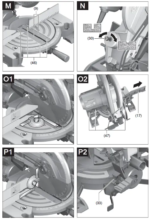 Always check the set mitre and/or bevel angle first by making trial cuts in scrap wood.
Checking and Adjusting the Basic Settings
To ensure precise cuts, the basic settings of the power tool must be checked and adjusted as necessary after intensive use. Experience and suitable special tools are required for this. A Bosch after-sales service point will handle this work quickly and reliably.
Aligning the fence
- Bring the power tool into the transport position.
- Turn the saw table (7) to the 0° detent (45). The lever (11) must be felt to engage in the detent.
- Pull the adjustable fence (17) all the way out.
Checking (see figure O1) - Set an angle gauge to 90° and position it flush with the saw blade (41) between the fence (6) and the saw blade on the saw table (7).
- The leg of the angle gauge must be flush with the fence over the complete length.
Setting (see figure O2) - Loosen all hex socket screws (47) with the hex key (22) provided.
- Rotate the fence (6) until the angle gauge is flush over the complete length.
- Re-tighten the screws.
Setting the Standard 0° Bevel Angle - Bring the power tool into the transport position.
- Turn the saw table (7) to the 0° detent (45). The lever (11) must be felt to engage in the detent.
Checking (see figure P1) - Set an angle gauge to 90° and place it on the saw table (7).
- The leg of the angle gauge must be flush with the saw blade (41) along its entire length.
Setting (see figure P2) - Loosen the clamping handle (26).
- Loosen the lock nut of the stop screw (33) using a commercially available ring spanner or open-ended spanner (13 mm).
- Turn the stop screw as far in or out as needed until the leg of the angle gauge is flush with the saw blade along its entire length.
- Retighten the clamping handle (26).
- Then retighten the lock nut of the stop screw (33). If the angle indicator (31) is not aligned with the 0° mark on the scale (32) following adjustment, loosen the screw (48) using a commercially available cross-headed screwdriver and align the angle indicator along the 0° mark. (See figure R)
Setting the standard 45° bevel angle - Bring the power tool into the work position.
- Turn the saw table (7) to the 0° detent (45). The lever (11) must be felt to engage in the detent.
- Loosen the clamping handle (26) and use the handle (3) to swivel the tool arm all the way to the left (45°).
Checking (see figure Q1)
- Set an angle gauge to 45° and place it on the saw table (7).
- The leg of the angle gauge must be flush with the saw blade (41) along its entire length.
Setting (see figure Q2) - Loosen the lock nut of the stop screw (23) using a commercially available ring spanner or open-ended spanner (13 mm).
- Turn the stop screw as far in or out as needed until the leg of the angle gauge is flush with the saw blade along its entire length.
- Retighten the clamping handle (26).
- Then retighten the lock nut of the stop screw (23).
- If the angle indicator (31) is not aligned with the 45° mark on the scale (32) following adjustment, first check the 0° setting for the bevel angle and the angle indicator once more. Then repeat the adjustment of the 45° bevel angle.
Transport (see figure S) - Before transporting the power tool, the following steps must be carried out:
- Bring the power tool into the transport position.
- Remove all accessories that cannot be securely fitted to the power tool.
- If possible, transport unused saw blades in a closed container.
- Carry the power tool by the transport handle (28) or hold it by the recessed handles (15) on the sides of the saw table.
- Only use the transport devices to transport the power tool and never the protective devices.
Maintenance and servicing
Maintenance and cleaning
- Pull the plug out of the socket before carrying out any work on the power tool.
- To ensure safe and efficient operation, always keep the power tool and the ventilation slots clean. In order to avoid safety hazards, if the power supply cord needs to be replaced, this must be done by Bosch or by an after-sales service centre that is authorised to repair Bosch power tools.
- The retracting blade guard must always be able to move freely and retract automatically. It is therefore important to keep the area around the retracting blade guard clean at all times.
- Always remove dust and chips after working by blowing out with compressed air or using a brush.
Accessories
Article number
3 601 M29 040, 3 601 M29 0B0: Extension bar 1 619 PA6 916
Saw blades for hardwood, composites, plastic and nonferrous metals
254 x 25.4 mm saw blade, 100 teeth 1 609 B00 844
Saw blades for wood and fibreboard, panels and strips
254 x 25.4 mm saw blade, 40 teeth 2 608 673 047
254 x 25.4 mm saw blade, 100 teeth 2 608 640 904
After-Sales Service and Application Service
Our after-sales service responds to your questions concerning maintenance and repair of your product as well as spare parts. You can find explosion drawings and information on spare parts at: www.bosch-pt.com The Bosch product use advice team will be happy to help you with any questions about our products and their accessories. In all correspondence and spare parts orders, please always include the 10‑digit article number given on the nameplate of the product.
Cambodia
Robert Bosch (Cambodia) Co., Ltd Unit 8BC, GT Tower, 08th Floor, Street 169, Czechoslovakia Blvd, Sangkat Veal Vong
Khan 7 Makara, Phnom Penh
VAT TIN: 100 169 511
Tel.: +855 23 900 685![]()
![]()
| Commercial type number | LV F -5005C -51803 | LVF-5005C -S0940 | LVF•5005C -54109 | LVF-5005N -51250 |
| Image format | 1/2.5-inch (Sensor diagonal 7.2 mm) | 1/2.5-inch (Sensor diagonal 7.2 mm) | 1/1.8-inch | 1/1.8-inch |
| Optical resolution | 5 Megapixets | 5 Megapixets | 5 Megapixels | 5 Megapixets |
| Zoom | ||||
| Focal length | 1.8 – 3 mm | 9 – 40 mm | 4.1 – 9 mm | 12 – 50 mm |
| Iris range (visible) | F1.8 to F7.4 | F1.5 to F7.4 | F1.6 to F8 | F1.8 to 1360 |
| IR iris range | same as visible | same as visible | same as visible | |
| Minimal object distance | 0.5 m (1.64 ft) | 2.5 m (8.2 ft) | 0.3 m (1 ft) | 0.8 m (2.63 ft) |
| Back focus length (values in air) | 8.3 mm (0.33 in) | 8.6 mm (wide): 13.19 mm (tele) | 12.72 mm (wide). 19.94 mm (tele) | 10.19 mm (wide). 10.12 mm (tele) |
| Flange back distance (values in air) | 12.5 mm | 12.5 mm | 12.5 mm | 17.526 mm |
| Lens mount | CS mount | CS mount | CS mount | C mount |
| Dimensions | ø 50 mm x 49.3 mm | ø 55 mm x 49.3 mm | ø 62.9 mm (excl. focus and zoom knobs) x 66.6 mm (excluding flange) | ø 52.4 mm x 89.3 mm |
| Weight | 63 g (0.134 lb) | 88 g (0.19 lb) | 130 g (0.29 lb) | 175 g (0.3861b) |
| Temperature range | -10° C to•50° C (+14° F to +122° F) | -10° C to+50° C (*14° F to *122° F) | -10° C to+50° C (+14° F to +122° F) | -10° C to•50° C (+14° F to +122° F) |
| IR corrected | yes | yes | yes | yes |
| Iris control | 4-pin SR-Iris | 4-pin SR-Iris | 4-pin SR-Iris | 4-pin. DC control |
| Zoom control | manual | manual | manual | manual |
| Focus control | manual | manual | manual | manual |
| Angle of view (HxV) | 4:3 mode: 115° x 99° Wide: 88° x 71° Tele 1/3-inch sensor 16:9: 109 x 82° Wide: 82° x 54° Tele 1/2.7-inch sensor 16:9: 116° x 84° Wide: 89° x 57° Tele |
4:3 mode: 36° x 27° Wide: 8.5° x 6.3° Tele 1/3-inch sensor 16:9: 33° x 17° Wide: 7.7° x 4.4° Tele 1/2.7-inch sensor 16:9: 37° x 20° Wide: 8.6° x 4.8° Tele |
4:3 mode: 100° x 74° Wide: 45° x 33° Tele 1/3-inch sensor 16:9: 73° x 41° Wide: 33° x 19° Tele 1/2.7-inch sensor 16:9: 80° x 44° Wide: 37° x 21° Tele 1/1.8-inch sensor 16:9: 101° x 56° Wide: 46° x 26° Tele |
4:3 mode: 133° x 25° Wide: 8° x 6° Tele 1/3-inch sensor 16:9: 24° x 14° Wide: 6° x 3° Tele 1/2.7-inch sensor 16:9: 27° x 16° Wide: 6.7° x 3.8° Tele 1/1.8-inch sensor 16:9: 33° x 19° Wide: 8.3° x 4.7° Tete |
| MTF on-axis (lp/mm) | NA | NA | NA | NA |
| MTF off-axis (Ip/mm) | NA | NA | NA | NA |
| Compatible cameras | DINION IP starlight 7000 HD DINION IP starlight 6000 HD DINION IP 5000 HD DINION IP 5000 MP DINION IP 4000 HD |
DINION IP starlight 7000 HD DINION IP starlight 6000 HD DINION IP 5000 HD DINION IP 5000 MP DINION IP 4000 HD |
DINION IP starlight 8000 MP DINION IP starlight 7000 HD DINION IP starlight 6000 HD DINION IP 5000 HD DINION IP 5000 MP DINION IP 4000 HD |
DINION IP starlight 8000 MP DINION IP starlight 7000 HD DINION IP starlight 6000 HD DINION IP 5000 HD DINION IP 5000 MP DINION IP 4000 HD |
![]()
| Commercial type number | LVF•8008C•PO413 | LFF-8012C-D35 | LFF-8012C•1350 | LVF-5003C•P2713 |
| Image format | 1/1.8-inch | 2/3-inch | 2/3-inch | 1/2.7′ |
| Optical resolution | ||||
| Zoom | N.A | |||
| Focal length | 4 – 13 mm | 35 mm | 50 mm | 2.7-13 mm |
| Iris range (visible) | F1.5 to close | F1.8. F2.8. F4. F8. F16 | F2. F2.8. F4. F8. F16 | F1.4 to close |
| IR iris range | same as visible | same as visible | same as visible | |
| Minimal object distance | 0.3 m (1 ft) | 1 m (3.3 ft) | 2 m (6.56 ft) | 0.3 m (1 ft) |
| Back focus Length (values in air) | 10.209 mm | 14.3 mm (0.56 in) | ||
| Flange back distance (values in air) | 12.5 mm | 17.526 mm | 14.8 mm (0.58 in) | |
| Lens mount | CS-mount | C-mount | C-mount | CS-mount |
| Dimensions | ∅ 65 x 93 mm | ∅ 53 x 47 mm | ∅ 54 x 47 mm | ∅ 47 mm (excluding focus and zoom knobs and iris block) x 75.11 mm |
| Weight | 172 g (0.38 lb) | 149 g (0.33 Ib) | 155 g (0.34 Ib) | 87 g (0.19 lb) |
| Temperature range | -10° C to•50° C (•14° F to •122° F) | -10° C to•50° C (•14° F to •122° F) | -10° C to•50° C (•14° F to •122° F) | -10° C to•50° C (•14° F to •122° F) |
| IR corrected | yes | yes | yes | yes |
| Iris control | P-iris stepping motor (120 steps) | manual | manual | P-iris stepping motor |
| Zoom control | manual | Rotational ring and locking screw | ||
| Focus control | manual | manual | manual | Rotational ring and locking screw |
| Angle of view (HxV) | 12MP mode (4:3): Wide: 90° x 67°: Tete: 29° x 21° 4K UHD mode (16:9): Wide: 86° x 48°: Tete: 27° x 15° |
12MP mode (4:3): 9.8° x 7.4° 4K UHD mode (16:9): 9.4° x 5.3° |
12MP mode (4:3): 6.8° x 5.1° 4K UHD mode (16:9): 6.6° x 3.7° |
113-inch sensor (16:9) – Wide: 113 x 60° Tele: 24.3 x 13.8° 1/2.7-inch sensor (16:9) – Wide: 126 x 66° Tele: 26.7 x 15.2° 1/2.8 inch sensor (16:9) Wide: 122 x 64° Tele: 25.9 x 14.7° |
| MTF on-axis (Ip/rnm) | NA | NA | NA | NA |
| MTF off-axis (lp/mm) | NA | NA | NA | NA |
| Compatible cameras | DINION IP ultra 8000 MP DINION IP starlight 8000 MP | DINION IP ultra 8000 MP DINION IP starlight 8000 MP DINION IP starlight 7000 HD DINION IP starlight 6000 HD DINION IP 5000 HD DINION IP 5000 MP DINION IP 4000 HD |
DINION IP ultra 8000 MP DINION IP starlight 8000 MP DINION IP starlight 7000 HD DINION IP starlight 6000 HD DINION IP 5000 HD DINION IP 5000 MP DINION IP 4000 HD |
DINION IP starlight 6000 HD (1/2.8-inch) DINION IP starlight 7000 HD (1/2.8-inch) |
BT-VS/MKC version 03_EN July 2020
]]>Bosch Universal Oxygen Sensor Installation Instructions
Please read these instructions carefully before removing the installed oxygen sensor from your vehicle
Tools required to perform installation:
Oxygen sensor removal tool or 22mm wrench
Wire cutter
Wire stripper
Tape measure
Contents of Bosch Universal Oxygen Sensor Connector Kit:
Bosch Universal Oxygen Sensor (Qty. 1)
Connector Body (Qty. 1)
Connector Cap (Qty. 1)
Posi-Lock* connectors (Qty. 4) *(Posi-Lock is a registered trademark of Swenco Co.)
Wire seals (Qty. 8)
Important Installation Notes (Please read these notes before the installation):
Before removing the original equipment oxygen sensor (hereinafter OE Sensor) from your vehicle, make note of the location of the connectors joining the oxygen sensor and vehicle wiring. The vehicle manufacturer has deemed this to be a suitable environment for a connection and it is recommended that the universal connector be installed close to the OE Sensor connection point if possible. Also note the
routing of the OE Sensor to ensure the Bosch Universal Oxygen Sensor is routed the same way.
Do not cut the wiring while removing the OE Sensor from the vehicle, as it is necessary to utilize a portion of this wiring on the Bosch Universal Oxygen Sensor.
Installation Steps:

Remove the OE Sensor from vehicle. This is a sample installation location. Oxygen sensors can be located in a manifold or exhaust pipe.

If there are special clips or grommets attached to the OE Sensor, proceed to Step 3. Otherwise, if the length from the hex/flange face to end of OE Sensor connector housing
is less than 29 1/2″, proceed to Step 4, otherwise, proceed to Step 5.
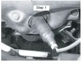
Cut the OE Sensor harness so as to include special clips or grommets. Lay the Bosch Universal Oxygen Sensor beside the OE Sensor and cut the Bosch Universal Oxygen Sensor wiring to the length of the OE Sensor,
but do not cut to less than 5″ (hex/flange face to end of sensor wire). Proceed to Step 6.
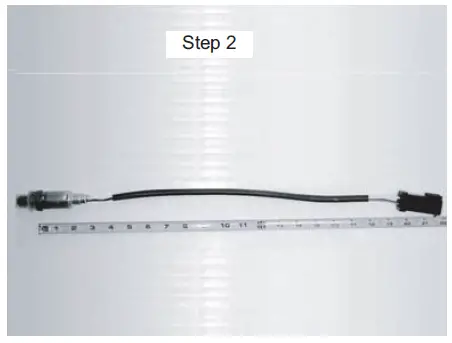
Cut the wiring of OE Sensor 4″ from end of connector as illustrated. Lay the Bosch Universal Oxygen Sensor beside the OE Sensor and cut the Bosch Universal Oxygen
Sensor wiring to the length of the OE Sensor. Proceed to Step 6.
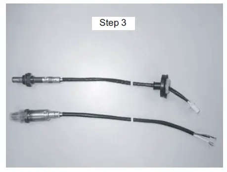
Lay the OE Sensor beside the Bosch Universal Oxygen Sensor and cut the OE Sensor wires to the same length as the Bosch Universal Oxygen Sensor length. Cut the wire
tie from the end of the Bosch Universal Oxygen Sensor wiring. Proceed to Step 6.
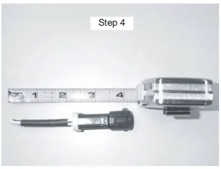
Strip 3/8″ of wire insulation from all wire ends. Use proper tools to ensure stripping only the insulation.
Oxygen Sensor Faces
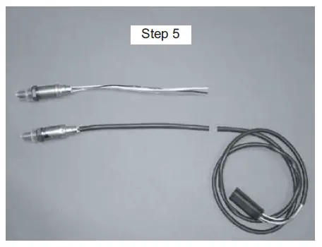
External Oil Contamination
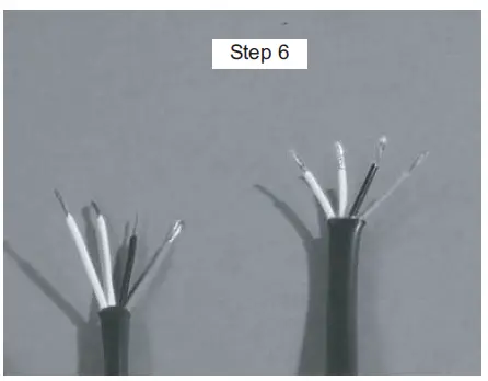
Fuel Contamination
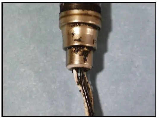
Coolant Contamination
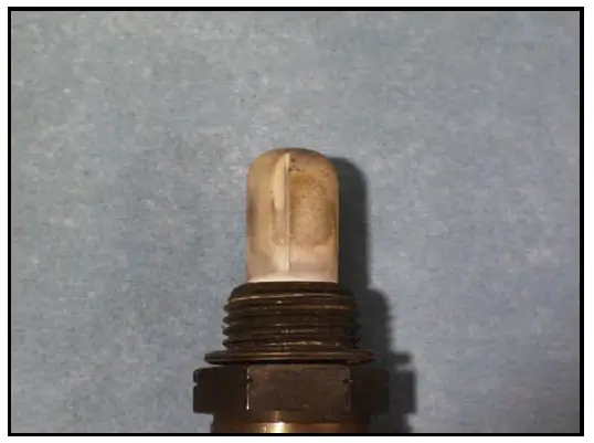
Oil Contamination
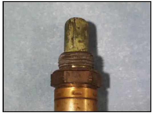
Fuel Contamination
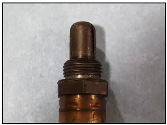
Utilizing “Wire Color Reference Table”, match the wires of the OE Sensor connector (column A) to the wires of Bosch Universal Oxygen Sensor (column B). Install the Connector Cap over the wires of the OE Sensor connector. Install the Connector Body over the wires of the Bosch Universal Oxygen Sensor.
Install a wire seal over each wire so that the unribbed end of the seal is facing the Connector Body and Cap. Check that the wires are aligned properly before proceeding.
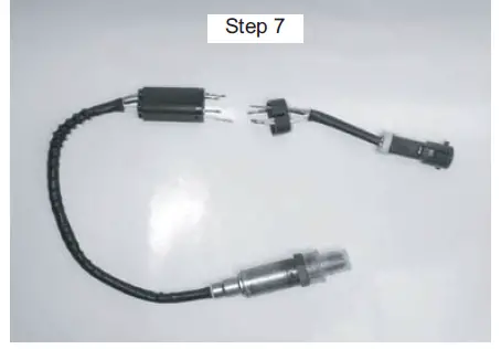
Insert a wire of the Bosch Universal Oxygen Sensor into the male end of the Posi-Lock connector. Keeping slight pressure on the wire, hand tighten the male end into the Posi- Lock barrel. Repeat for the remaining wires of the Bosch Universal Oxygen Sensor, and insert wires of the OE Sensor connector into the male ends of the Posi-Lock connectors.
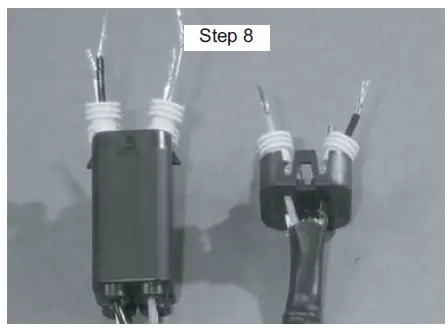
Utilizing “Wire Color Reference Table”, begin connecting the wires of the OE Sensor connector harness as described in Step 7. Be sure to avoid criss-crossing the wires. Grasp the wire on each side of the Posi-Lock
connector and pull firmly to insure proper assembly.
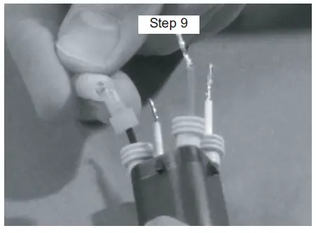
Push the wire seals against the Posi-Lock connector. Insert the Posi-Lock and wire seals into the Connector Body. Push the Connector Cap down onto the Connector Body until both
tabs lock into position.
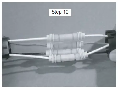
Remove the protective cap from the Bosch Universal Oxygen Sensor and re-install onto vehicle. It is critical to locate wires away fromb sources of extreme heat and possible
abrasion, utilizing any clips or grommets from the OE Sensor wire harness.
Wire Color Reference Table:
|
OE Sensor Types |
Signal Wire | Heater Wires* (2 wires) | Ground Wire (optional) | |||
|
OE Sensor (A)** |
Bosch Universal Oxygen Sensor (B)** |
OE Sensor (A)** |
Bosch Universal Oxygen Sensor (B)** |
OE Sensor (A)** |
Bosch Universal Oxygen Sensor (B)** | |
| Bosch | Black |
Black |
White |
White |
Gray |
Gray |
| Type A | Purple | Dark Brown | Light Brown | |||
| Type B | Blue | Black | White | |||
| Type C | White | Black | Green | |||
| Type D | Black | White | Gray | |||
| 1996-95 Mazda Millenia (V6-2.5L)
1996-95 Ford Probe, Mazda 626 (V6) |
Black | White | Red | |||
| 1995-91 Geo Tracker, Suzuki
Sidekick |
Black | Red | No Ground | |||
* Since there is no polarity to the heaters, it is only important to match the color of the heater wires.
** Wire color(s) of column (A) in each wire type should match wire color(s) of column (B).

Register your new device on MyBosch now and get free benefits: bosch-home.com/welcome
Extractor hood
DLN54AA70A
Instruction manual
Extractor hood
Additional information on products, accessories, replacement parts, and services can be found at www.bosch-home.com and in the online shop www.bosch-eshop.com

Read these instructions carefully. Only then will you be able to operate your appliance safely and correctly. Retain the instruction manual and installation instructions for future
use or for subsequent owners.
The appliance can only be used safely if it is correctly installed according to the safety instructions. The installer is responsible for ensuring that the appliance works perfectly at its installation location.
This appliance is intended for domestic use and the household environment only. The appliance is not intended for use outside. Do not leave the appliance unattended during operation. The manufacturer is not liable for damage which is caused by improper use or incorrect operation.
This appliance is intended for use up to a maximum height of 2000 meters above sea level.
This appliance may be used by children over the age of 8 years old and by persons with reduced physical, sensory or mental capabilities or by persons with a lack of experience or knowledge if they are supervised or are instructed by a person responsible for their safety how to use the appliance safely and have understood the associated hazards.
Children must not play with, on, or around the appliance. Children must not clean the appliance or carry out general maintenance unless they are at least 15 years old and are
being supervised.
Keep children below the age of 8 years old at a safe distance from the appliance and power cable.
Check the appliance for damage after unpacking it. Do not connect the appliance if it has been damaged in transport. This appliance is not intended for operation with an external clock timer or remote control.

 Warning – Danger of suffocation!
Packaging material is dangerous to children. Never allow children to play with packaging material.
Warning – Danger of death! Risk of poisoning from flue gases that are drawn back in.
Always ensure adequate fresh air in the room if the appliance is being operated in the exhaust air mode at the same time as room independent heat-producing appliance is being operated.
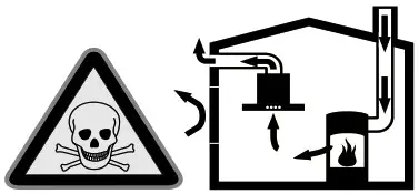
Room air-dependent heat-producing appliances (e.g. gas, oil, wood or cooperated heaters, continuous flow heaters or water heaters) obtain combustion air from the room in which they are installed and discharge the exhaust gases into the open air through an exhaust gas system (e.g. a chimney). In combination with an activated vapor extractor hood, room air is extracted from the kitchen and neighboring rooms – a partial vacuum is produced if not enough fresh air is supplied. Toxic gases from the chimney or the extraction shaft are sucked back into the living space.
- Adequate incoming air must therefore always be ensured.
- An incoming/exhaust air wall box alone will not ensure compliance with the limit.
Safe operation is possible only when the partial vacuum in the place where the heat-producing appliance is installed does not exceed 4 Pa (0.04 bar). This can be achieved when the air needed for combustion is able to enter through openings that cannot be sealed, for example in doors, windows, incoming/exhaust air wall boxes, or by other technical means.

In any case, consult your responsible Master Chimney Sweep. He is able to assess the house’s entire ventilation setup and will suggest suitable ventilation measures to you.
Unrestricted operation is possible if the vapor the extractor hood is operated exclusively in the circulating-air mode.
Warning – Risk of fire!
- Grease deposits in the grease filter may catch fire. Clean the grease filter at least once a month. Never operate the appliance without the grease filter.
- Grease deposits in the grease filter may catch fire. Never work with naked flames close to the appliance (e.g. flambéing). Do not install the appliance near a heat-producing appliance for solid fuel (e.g. wood or coal) unless a closed, nonremovable cover is available. There must be no flying sparks.
- Hot oil and fat can ignite very quickly. Never leave hot fat or oil unattended. Never use water to put out burning oil or fat. Switch off the hotplate. Extinguish flames carefully using a lid, fire blanket or something similar.
- When gas burners are in operation without any cookware placed on them, they can build up a lot of heat. A ventilation appliance installed above the cooker may become damaged or catch fire. Only operate the gas burners with cookware on them.
- Operating multiple gas hotplates at the same time generates a great deal of heat. The ventilation appliance may become damaged or catch fire. The ventilation the appliance must only be combined with gas hotplates that do not exceed the following values:
– Total maximum output: 9.75 kW
– Maximum output for a single burner:
4 kW
– Total maximum output of rear hobs:
5.25 kW
Warning – Risk of burns!
The accessible parts become very hot when in operation. Never touch hot parts. Keep children at a safe distance.
Warning – Risk of injury!
■ Components inside the appliance may have sharp edges. Wear protective gloves.
■ Items placed on the appliance may fall down. Do not place any objects on the appliance.
■ The light emitted by LED lights is very dazzling and can damage the eyes (risk group 1). Do not look directly into the switched-on LED lights for longer than 100 seconds.
Warning – Risk of electric shock!
■ A defective appliance may cause electric shock. Never switch on a defective appliance. Unplug the appliance from the mains or switch off the circuit breaker in the fuse box. Contact the after-sales service.
■ Incorrect repairs are dangerous. Repairs may only be carried out and damaged power cables replaced by one of our trained after-sales technicians. If the appliance is defective, unplug the appliance from the mains or switch off the circuit breaker in the fuse box. Contact the aftersales service.
■ Do not use any high-pressure cleaners or steam cleaners, which can result in an electric shock.
Causes of damage
Caution!
Risk of damage due to corrosion. Always switch on the appliance while cooking to avoid condensation. Condensate can produce corrosion damage.
Always replace faulty bulbs to prevent the remaining bulbs from overloading. Risk of damage due to ingress of humidity into the electronic circuitry. Never clean operator
controls with a wet cloth.
Surface damage due to incorrect cleaning.
Clean stainless steel surfaces in the direction of the grain only. Do not use any stainless steel cleaners for operator controls.
Surface damage due to strong or abrasive cleaning agents. Never use strong and abrasive cleaning agents.
Risk of damage from returning condensate. Install the exhaust duct in such a way that it falls away from the appliance slightly (1° slope).

Your new appliance is particularly energy-efficient. Here you can find tips on how to save even more energy when using the appliance, and how to dispose of your appliance properly.
Saving energy
- During cooking, ensure that there is a sufficient supply of air to enable the extractor hood to work efficiently and with a low level of operating noise.
- Adjust the fan speed to the amount of steam produced during cooking. Only use intensive mode when required. The lower the fan speed, the less energy is consumed.
- If cooking produces large amounts of steam, select a higher fan speed in good time. If the cooking steam has already spread around the kitchen, the extractor hood will need to be operated for longer.
- Switch off the extractor hood if you no longer require it.
- Switch off the lighting if you no longer require it.
- Clean and (if required) replace the filter at regular intervals in order to increase the effectiveness of the ventilation system and to prevent the risk of fire.
- Put the lid on to reduce cooking steam and condensation.
Environmentally-friendly disposal
Dispose of packaging in an environmentally friendly manner.
 This appliance is labeled in accordance with European Directive 2012/19/EU concerning used electrical and electronic appliances (waste electrical and electronic equipment – WEEK). The guideline determines the framework for the return and recycling of used appliances as applicable throughout the EU.
 Operating modes
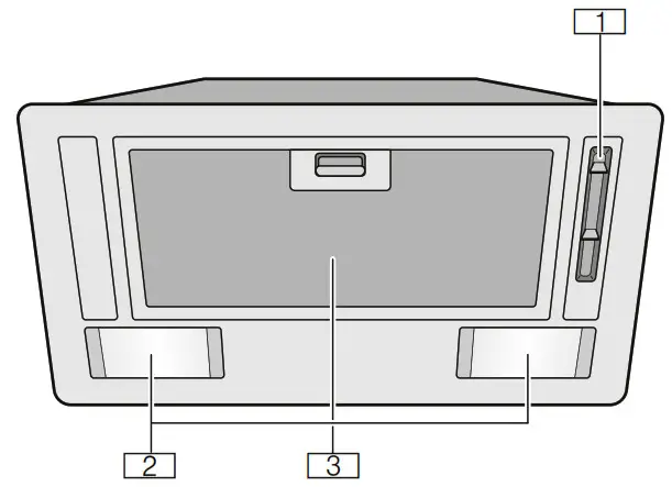
Exhaust air mode
The air which is drawn in is cleaned by the grease filters and conveyed to the exterior by a pipe system.
Note: The air must not be discharged into a flue that is used for exhausting fumes from appliances burning gas or other fuels (not applicable to appliances that only discharge the air back into the room).
- Before conveying the exhaust air into a non-functioning smoke or exhaust gas flue, obtain the consent of the heating engineer responsible.
- If the exhaust air is conveyed through the outer wall, a telescopic wall box should be used.
Air recirculation
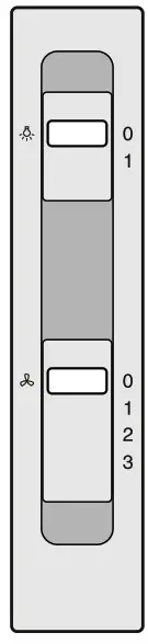 The air which is drawn in is cleaned by the grease filters and an activated carbon filter and is conveyed back into the kitchen.
Note: To bind odors in air recirculation mode, you must install an activated carbon filter. The different options for operating the appliance in air recirculation mode can be found in the brochure. Alternatively, ask your dealer. The required accessories are available from specialist retailers, from customer service or from the Online Shop.

Here, you can get to know your appliance and receive information about the accessories.

- Control panel
- Lighting
- Metal grease filter
Control panel
| Symbol | Setting | Explanation |
 |
0 | Switches off the fan |
| 1 | Switches on fan setting 1 | |
| 2 | Switches on fan setting 2 | |
| 3 | Switches on fan setting 3 | |
|
0 | Switches off the lighting |
| 1 | Switches on the lighting |

Special accessories
| Accessory/ies | Order number |
| Active carbon filter (replacement filter) | DWZ0IN0A0 |
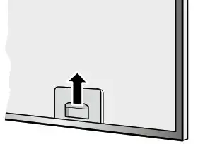 Air recirculation accessory set (initial equipment) DWZ0IN0T0
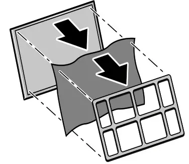
 Operating the appliance
Note: Switch on the extractor hood when you start cooking and switch it off again several minutes after you have finished cooking. This is the most effective way of removing kitchen fumes.
Switching the appliance on and off
Switching on the appliance
Set the slide control to position 1.
Selecting the fan setting
Set the slide control to position 1, 2 or 3.
Switching off the appliance
Set the slide control to position 0.
Lighting
The lighting can be switched on and off independently of the ventilation.
Set the slide control to position 1.

Warning – Risk of burns!
The appliance becomes hot during operation. Allow the appliance to cool down before cleaning.
Warning – Risk of electric shock!
Penetrating moisture may result in an electric shock.
Clean the appliance using a damp cloth only. Before cleaning, pull out the mains plug or switch off the circuit breaker in the fuse box.
Warning – Risk of electric shock!
Do not use any high-pressure cleaners or steam cleaners, which can result in an electric shock.
Cleaning agents
To ensure that the different surfaces are not damaged by using the wrong cleaning agent, observe the information in the table. Do not use any of the following:
- Harsh or abrasive cleaning agents,
- Cleaning agents with high alcohol content,
- Hard scouring pads or cleaning sponges,
- High-pressure cleaners or steam cleaners.
Wash new sponge cloths thoroughly before use. Follow all instructions and warnings included with the cleaning agents.
| Area | Cleaning agent |
| Stainless steel | Hot soapy water: Clean with a dishcloth and then dry with a soft cloth. Clean stainless steel surfaces in the grind direction only. Special stainless steel cleaning products are available from our after-sales service or from specialist retailers. Apply a very thin layer of the cleaning product with a soft cloth. |
| Painted surfaces | Hot soapy water: Clean using a damp dishcloth and dry with a soft cloth/towel. Do not use any stainless steel cleaners. |
| Aluminium and plastic | Glass cleaner: Clean with a soft cloth. |
| Glass | Glass cleaner: Clean with a soft cloth. Do not use a glass scraper. |
| Controls | Hot soapy water: Clean using a damp dishcloth and dry with a soft cloth/towel. Risk of electric shock caused by penetrating moisture. Risk of damage to the electronics from penetrating moisture. Never clean operating controls with a wet cloth. Do not use any stainless steel cleaners. |
Removing and installing the filter
The filter must be serviced regularly in order to guarantee efficient filtration of odors and grease.
Metal grease filter
The metal grease filters should be cleaned every 30 operating hours or at least once a month.
Warning – Risk of fire!
Grease deposits in the grease filter may catch fire.
Clean the grease filter at least once a month.
Never operate the appliance without the grease filter.
Removing metal grease filter
The metal grease filters filter the grease out of kitchen steam. To keep them in good working order, the filters should be cleaned at least once a month.

- Open the lock on the metal grease filters and remove the filters from the retainer.
Notes
– When you do this, take hold of the metal grease filters from underneath with your other hand.Make sure that the metal grease filters do not fall and damage the hob.
– Fat may accumulate in the bottom of the metal grease filters. Hold the filter’s level to prevent fat from dripping out. - Clean the metal grease filters.
- Clean the inside of the appliance.
Cleaning the metal mesh grease filters
Notes
- Do not use any aggressive, acidic or alkaline cleaning agents.
- When cleaning the metal mesh grease filters, also clean the holder for the metal mesh grease filters in the appliance using a damp cloth.
- The metal mesh grease filters can be cleaned in the dishwasher or by hand.
By hand:
Note: You can use a special grease solvent for stubborn dirt. It can be ordered via the Online Shop.
- Soak the metal mesh grease filters in a hot soapy solution.
- Clean the filters with a brush and then rinse them thoroughly.
- Leave the metal mesh grease filters to drain.
In the dishwasher:
Note: If the metal mesh grease filters are cleaned in the dishwasher, slight discoloration may occur. This has no effect on the function of the metal mesh grease filters.
- Do not clean heavily soiled metal mesh grease filters together with utensils.
- Place the metal mesh grease filters loosely in the dishwasher. The metal mesh grease filters must not be wedged in.
Installing the metal mesh grease filter
1. Insert metal grease filter.
2. Fold up metal grease filter and engage the lock.
Note: Make sure that the filter lock engages properly.
Activated charcoal filter (only in circulating-air mode)
To ensure effective odor removal, the filter must be serviced regularly.
The activated charcoal filters must be replaced at least every 3 months.
Notes
- The activated charcoal filters are not included with the appliance. The activated charcoal filters are available from specialist retailers, from our aftersales service or from our online shop.
- The activated charcoal filters cannot be cleaned or reactivated.
- Only use genuine replacement filters. This will ensure that the appliance performs optimally.
Removing the activated charcoal filter (only in circulating-air mode)
Activated charcoal filters trap the odor-causing compounds in cooking smells. They are only used for circulating-air mode.
- Remove the metal grease filter.
- Remove the grille and metal grease filter.

Fitting the activated charcoal filter
- Place the activated charcoal filter onto the metal grease filter.
- Fix the activated charcoal filter to the grille.

Malfunctions often have simple explanations. Please read the following notes before calling the after-sales service.
Warning – Risk of electric shock!
Incorrect repairs are dangerous. Repairs may only be carried out and damaged power cables replaced by one of our trained after-sales technicians. If the appliance is defective, unplug the appliance from the mains or switch off the circuit breaker in the fuse box. Contact the after-sales service.
Fault table
| Problem | Possible cause | Solution |
| The appliance does not work | The plug is not plugged into the mains | Connect the appliance to the power supply |
| Power cut | Check whether other kitchen appliances are working | |
| The fuse is faulty | Check in the fuse box to make sure that the fuse for the appliance is in working order | |
| The lighting does not work. | The LED lights are defective. | You can read about this in the section entitled “Replacing the LED lights”. |
Replacing the LED lights
Warning – Risk of electric shock!
When changing the bulbs, the bulb socket contacts are live. Before changing the bulb, unplug the appliance from the mains or switch off the circuit breaker in the fuse box.
Warning – Risk of injury!
The light emitted by LED lights is very dazzling and can damage the eyes (risk group 1). Do not look directly into the switched-on LED lights for longer than 100 seconds.
Important! Only use bulbs of the same type and wattage.

- Loosen and remove the bulb cover.
- Unscrew the bulb and replace it with a bulb of the same type.

- Refit the bulb cover.
- Plugin the mains plug and switch the circuit breaker back on.

When calling us, please give the product number (E no.) and the production number (FD no.) so that we can provide you with the correct advice. The rating plate with these numbers can be found inside the appliance (remove the metal mesh grease filter to gain access).
You can make a note of the numbers of your appliance and the telephone number of the after-sales service in the space below to save time should it be required.
| E no. | FD no. |
After-sales service
Please be aware that a visit by an after-sales engineer will be charged if a problem turns out to be the result of operator error, even during the warranty period.
Please find the contact data of all countries in the enclosed customer service list.
To book an engineer visit and product advice
| GB | 0344 892 8979 Calls are charged at local or mobile rates. |
| IE | 0344 892 8979 Calls are charged at local or mobile rates. |
Rely on the professionalism of the manufacturer. You can therefore be sure that the repair is carried out by trained service technicians who carry original spare parts for your appliances.
 ……………………….
 Thank you for buying a
Register your new device on MyBosch now and profit directly from:
- Expert tips & tricks for your appliance
- Warranty extension options
- Discounts for accessories & spare parts
- Digital manual and all appliance data at hand
- Easy access to Bosch Home Appliances Service
Free and easy registration – also on mobile phones: www.bosch-home.com/welcome
 Looking for help?
You’ll find it here.
Expert advice for your Bosch home appliances need help with problems or a repair from Bosch experts.
Find out everything about the many ways Bosch can support you: www.bosch-home.com/service
Contact data of all countries are listed in the attached service directory.
Robert Bosch Hausgerate GmbH Carl-Wery-StraBe 34
81739 Munchen
Germany
www.bosch-home.com

9001420964
981109
Instruction Manual
Register your new device on IVyBosch now and get free benefits: bosch-home.com/welcome
Safety instructions
This appliance complies with the relevant safety regulations for electrical appliances and is fitted with noise suppression.
The refrigeration circuit has been checked for leaks.
About these instructions
- Read and follow the instructions for installation and use. They contain important information on how to install, use and maintain the appliance.
- The manufacturer is not liable if you disregard the notifications and warnings in the operating and installation instructions.
- Retain all documents for subsequent use or for the next owner.
Risk of explosion
- Never use electrical appliances inside the appliance (e.g. heaters or electric ice makers).
- Do not store products which contain flammable propellant (e.g. spray cans) or explosive substances in the appliance.
- Keep high-percentage alcohol tightly sealed and store in an upright position.
- Do not use additional means to accelerate the defrosting process other than those recommended by the manufacturer.
Risk of electric shock
Improper installations and repairs may put the user at considerable risk.
- When installing the appliance, ensure that the main cable is not trapped or damaged.
- If the mains cable is damaged: immediately disconnect the appliance from the electricity supply.
- Do not use multi-outlet power strips, extension leads, or adapters.
- Has the appliance been repaired by the manufacturer, Customer Service, or a similarly qualified person only?
- Use original parts supplied by the manufacturer only.
The manufacturer guarantees that these parts satisfy the safety requirements.
Risk of cold burns
- Never put frozen food straight from the freezer compartment into your mouth.
- Avoid prolonged contact between your skin and frozen food, ice, and the tubes in the freezer compartment.
Risk of injury
Containers that contain carbonated beverages may burst.
Do not store containers that contain carbonated beverages in the freezer compartment.
 Fire hazard/Danger due to refrigerants
The tubes of the refrigeration circuit convey a small quantity of an environmentally friendly but flammable refrigerant (R600a). It does not damage the ozone layer and does not contribute to the greenhouse effect.
If refrigerant escapes, it may injure your eyes or ignite.
- Do not damage the tubes.
If the tubes are damaged:
- Keep naked flames and ignition sources away from the appliance.
- Ventilate the room.
- Switch off the appliance and pull out the main plug.
- Please contact Customer Service.
 Fire hazard
Portable multi-outlet power strips or power supplies may overheat, causing a fire. Never leave portable multi-outlet power strips or portable power supplies behind the appliance.
Avoiding placing children and vulnerable people at risk here are:
- Children,
- People with limited physical, mental, or sensory abilities,
- People who have inadequate knowledge concerning the safe operation of the appliance.
Measures:
- Ensure that children and vulnerable people have understood the hazards.
- A person responsible for safety must supervise or instruct children and vulnerable people who using the appliance.
- Only children aged 8 years and above may use the appliance.
- Supervise children who are cleaning and maintaining the appliance.
- Never allow children to play with the appliance.
Risk of suffocation
- If the appliance features a lock: keep the key out of the reach of children.
- Keep children away from the packaging and its parts.
Damage to property
To prevent damage to property:
- Do not stand or support yourself on the base, runners, or doors.
- Keep plastic parts and door seals free of oil and grease.
- Pull-on the mains plug – not the power cord.
Weight
When installing and transporting the appliance, note that it may be very heavy.
Intended use
Use this appliance
- Only for freezing food and making ice.
- Only in the home and in the home environment.
- Only according to this user manual.
This appliance is intended for use up to a maximum height of 2000 meters above sea level.
Directions for disposal
 Disposing of packaging
The packaging protects your appliance from damage during transport. All the materials used are environmentally friendly and can be recycled. Please help by disposing of the packaging in an environmentally responsible manner.
Information about the available disposal methods and sites can be obtained from your appliance retailer or your local authority.
Disposing of your old appliance
Used appliances are not valueless waste. Valuable raw materials can be recovered through environmentally responsible disposal.
 This appliance is labeled in accordance with European Directive 2012/19/EU concerning used electrical and electronic appliances (waste electrical and electronic equipment – WEEE).
The Directive determines the framework for the return and recycling of used appliances as applicable throughout the EU.
 Warning
Appliances at the end of their useful life:
- Unplug the mains plug.
- Cut the power cord and remove it along with the main plug.
- Do not remove the shelves and containers. Leaving them intact makes it more difficult for children to climb in.
- Never let children play with a disused appliance.
Risk of asphyxiation!
Refrigerators contain refrigerant as well as gases in the insulation material. Refrigerant and gases must be disposed of properly. Do not damage the refrigerant circuit pipes before disposing of them properly.
Specifications supplied
After unpacking the appliance, check all parts for transport damage.
If you find any defects, contact the retailer from whom you purchased the appliance or our After-sales Service.
The appliance supplied consists of the following components:
- Free-standing appliance
- Features (vary depending on the model)
- Bag of assembly materials
- Instructions for use and installation
- Service record
- Guarantee slip
- Information on energy consumption and noise
Installing the appliance
Transport
Because of the weight and size of the appliance, and in order to minimize the risk of personal injury or damage to the appliance, at least two persons are required for moving and positioning the appliance safely.
Installation site
The ideal installation site is a dry, well-ventilated room.
The appliance should not be installed in a position that is exposed to direct sunlight or close to a source of heat, such as a cooker or radiator. If installation near to a source of heat is unavoidable, use a suitable insulating panel or keep to the following minimum distances from the source of heat:
- 3 cm from an electric or gas cooker.
- 30 cm from oil or solid fuel cookers.
Floor surface
The floor at the installation site must not give. Reinforce the floor if necessary.
Wall clearance
If the appliance is positioned in the corner of a room or a recess, minimum clearances at the sides must be maintained so that the heated air is able to escape unimpeded and the appliance door can be fully opened.

Observe the room temperature and ventilation requirements
Room temperature
The appliance is designed for a certain climate class.
Depending on the climate class, the appliance can be operated at the following ambient temperatures.
The climate class is specified on the rating plate.
| Climate class | Permissible room temperature |
| SN | +10 °C to 32 °C |
| N | +16 °C to 32 °C |
| ST | +16 °C to 38 °C |
| T | +16 °C to 43 °C |
Note
The appliance is fully functional within the room temperature limits of the specified climate class. If an appliance in the SN climate class is operated at lower ambient temperatures, damage to the appliance can be excluded up to a temperature of +5 °C.
Ventilation
The heated air must be able to escape unimpeded.
Otherwise, the refrigerating unit has to work harder, which increases the appliance’s power consumption.
Therefore:
- Never cover over or block the air vent.
- Keep minimum distances to walls and furniture.
Connecting the appliance
After setting up the appliance, wait for at least 4 hours before starting the appliance up. The oil contained in the compressor may have been displaced into the refrigeration system during transport.
Before starting the appliance up for the first time, clean its interior (see section headed Cleaning the appliance).
Electrical connection
The socket must be near to the appliance and easily accessible after the appliance has been installed.
The appliance conforms to protection class I. Connect the appliance to a 220-240 V/50 Hz alternating current supply using a socket with a protective earthing conductor which has been correctly installed. The socket must be protected by a fuse with a rating of 10 A to 16 A.
In the case of appliances operated outside of Europe, check whether the voltage and type of current specified conform to the values of your electricity grid. You will find this information on the rating plate.
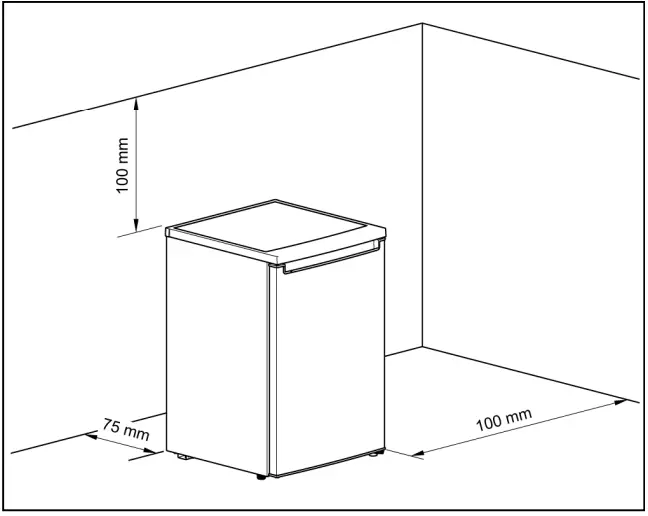
Warning
The appliance must never be connected up to an electronic energy-saving socket.
Sinusoidal-commutated and line-commutated inverters can be used with our appliances. Line-commutated inverters are used with photovoltaic systems that are connected directly to the national grid. Sinusoidalcommunicated inverters must be used with standalone applications (e.g. on ships or mountain huts) that do not have a direct connection to the national grid.
Aligning the appliance
Note
To ensure that it functions properly, the appliance must be aligned using a spirit level.
- Move the appliance into its intended installation position.
- Screw the feet in/out until the appliance is exactly aligned.
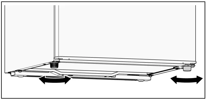
Changing the door hinge
We recommend having the door hinge changed by our customer service. How much a door hinge change will cost you can find out by contacting customer service.
Warning
When the door hinge is changed, the appliance must not be connected to the power supply. Please pull the mains plug beforehand.
Required tools
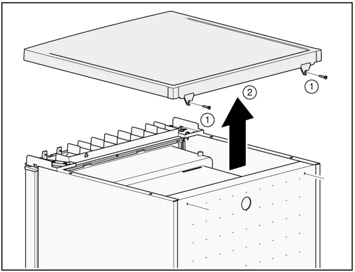
Changing door hinge of the appliance door
- Open the appliance door and unhinge and remove all fittings from inside the appliance (see section headed Fittings).
- Unscrew the 2 screws (1).
- Take off the cover plate (2) and set it down on a soft surface.
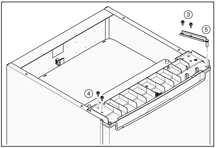 Hold on to the appliance door!
 - Unscrew the 2 screws (3).
- Unscrew the 2 screws (4).
- Remove the top hinge (5).
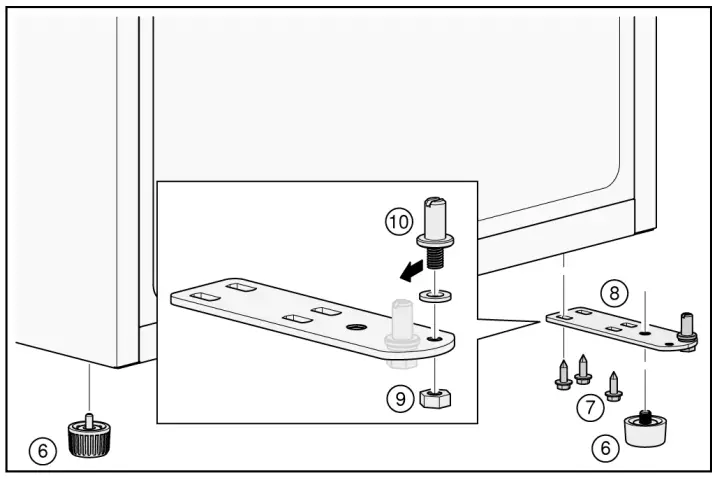
- Unhook the appliance door and set it down on a soft surface.
- To avoid damaging the appliance’s rear side, provide cushioning material. Place the appliance carefully onto its rear side.
- Unscrew the feet (6).
- Unscrew the 3 screws (7).
- Remove the bottom hinge (8).
- Unscrew the nut (9) and pull out the bolt (10).
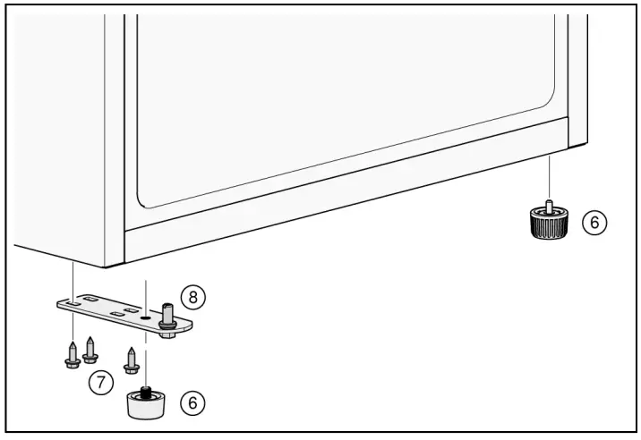
- Insert the bolt (10) into the left boring and apply the nut (9) and tighten.
- Apply the bottom hinge (8) and apply 3 screws (7) and tighten.
- Screw the feet (6) into the bottom hinge (8).
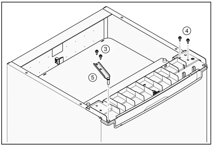
- Attach the appliance door to the bottom hinge (8).
- Apply the 2 screws (4) and tighten.
- Apply the top hinge (5) and apply the 2 screws (3) and tighten.
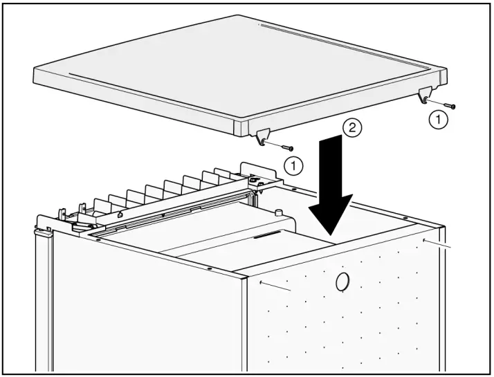
- Turn the appliance upright again.
- Mount the cover panel (2) at the front and lay it flat on the rear.
- Apply the 2 screws (1) and tighten.
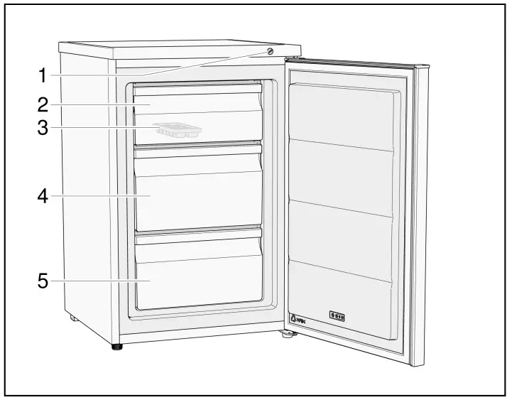
- Open the appliance doors and attach all fittings (see section headed Fittings).
Getting to know the appliance
Appliance
The features of the models may vary.
The illustrations may differ from your particular model.
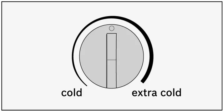
- Temperature controller
- Upper frozen food container
- Ice-cube tray
- Medium frozen food container
- Lower frozen food container
Switching on the appliance
Plug the mains plug into the mains outlet socket.
The appliance will start cooling.
Notes on using the appliance
- After switching on the appliance, it may be several hours before the set temperature is reached.
Do not put any food in the appliance before then. - If you cannot open the appliance door again immediately after closing it, wait a moment for the low pressure created to equalize.
Setting the temperature
Freezer compartment
Use a coin to turn the temperature controller to the required setting.
We recommend a medium temperature setting.
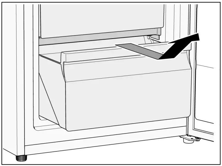
cold: Warmer temperature
extra cold: Cooler temperature (higher energy consumption)
Usable capacity
You will find the details of the usable capacity on the rating plate inside the appliance.
Using the entire freezing capacity
To accommodate the maximum quantity of frozen food, you can remove all of the fittings from inside the appliance. You can then stack the food directly on the bottom of the freezer compartment.
How to remove and refit the fittings is described in the section headed Fittings.
Freezer compartment
Use the freezer compartment for the following
- Storing deep-frozen food.
- To make ice cubes.
- To freeze food.
Note
Make sure that the appliance door is always closed.
When the appliance door is open, the frozen foods defrost and the freezer compartment ices up heavily. In addition: Energy is wasted due to power consumption.
Max. freezing capacity
You will find information on the maximum freezing capacity in 24 hours on the rating plate.
Conditions for use of max. freezing capacity
- Remove the fittings.
- Stack the food directly on the bottom of the freezer compartment.
Freezing and storing
Purchasing frozen foods
- Packaging must not be damaged.
- Observe the best before date.
- The temperature in the commercial chest freezer must be -18 °C or colder.
- As far as possible, frozen food must be transported in an insulated container and quickly placed in the freezer compartment.
When arranging the food, note the following
Spread the items out well in the frozen food containers.
Note
Food that is already frozen must not come into contact with the food that is to be freshly frozen.
Storing frozen food
Avoid contact between food and rear panel. Otherwise, the air circulation will be impaired.
Food or packaging could freeze to the rear panel.
Freezing fresh food
Only use fresh, undamaged food for freezing.
In order to retain the nutritional value, aroma, and color of the food as much as possible, blanch vegetables before they are frozen.
Blanching is not required for aubergines, peppers, courgettes, and asparagus.
You can find literature about freezing and blanching in bookshops.
Note
Do not allow food that is to be frozen to sit right next to food that has already been frozen.
- The following are suitable for freezing:
Baked goods, fish and seafood, meat, game, poultry, vegetables, fruit, herbs, eggs without their shells, dairy products such as cheese, butter, and curd cheese, prepared dishes and leftovers such as soups, stews, cooked meat, and fish, potato dishes, baked casseroles, and sweet foods. - The following are not suitable for freezing:
Types of vegetables that are usually eaten raw, such as lettuces or radishes, eggs in their shells, grapes, whole apples, pears and peaches, hard-boiled eggs, yogurt, curds, soured cream, crème fraîche, and mayonnaise.
Packing frozen food
Pack food so that it is airtight to prevent it from losing its flavor or drying out.
- Store food in its packaging.
- Press out any air.
- Close the packaging tightly.
- Label packaging with its contents and date of freezing.
The following are suitable as packaging:
Plastic film, polyethylene hose film, aluminum foil, freezer bags.
You will find these products at your specialist dealer.
The following are not suitable as packaging:
Wrapping paper, greaseproof paper, cellophane, rubbish bags, and used shopping bags.
The following are suitable for sealing packaging:
Rubber bands, plastic clips, pack-twines, cold-resistant scotch tape, or similar.
Polyethylene bags and hose film can be fused closed using a bag sealer.
Storage life of frozen foods
The storage life depends on the type of food.
At a temperature of -18 °C:
- Fish, sausages, prepared dishes, baked goods: Up to 6 months.
- Cheese, poultry, meat: Up to 8 months.
- Vegetables, fruit: Up to 12 months.
Defrosting frozen food
You can choose between the following options, depending on the type of food and its intended use:
- at ambient temperature
- in the fridge
- in an electric oven, with/without hot air convection
- In the microwave oven.
Caution
Do not refreeze defrosted food. It can only be refrozen after it has been made into a ready-to-eat meal (cooked or roasted).
Do not continue to use the complete max. storage time for the frozen food.
Fittings
Frozen food container
The frozen food containers can be removed for loading and unloading and cleaning.
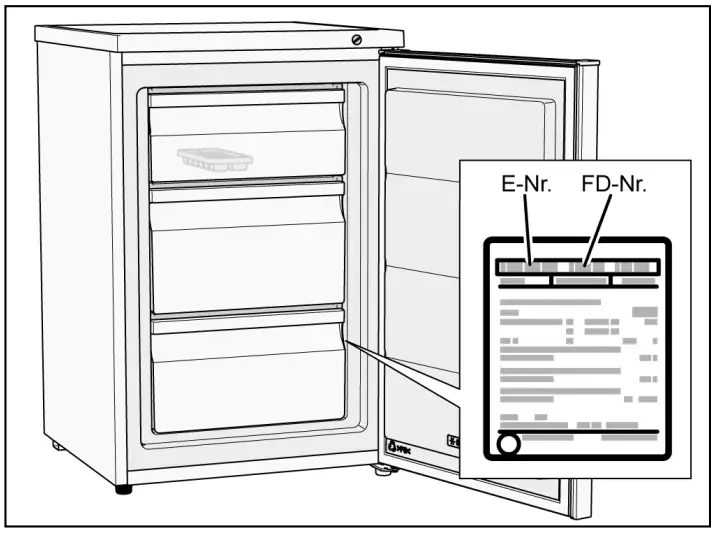
Ice-cube tray
The ice-cube tray is for producing and keeping ice cubes in.

- Fill the ice-cube tray ¾ full of drinking water and place in the frozen food container.
- If the ice-cube tray is stuck to the freezer compartment, loosen with a blunt implement only (spoon-handle).
- To loosen the ice cubes, twist the ice-cube tray slightly or hold briefly under flowing water.
Switching off and shutting down the appliance
Switch off the appliance
Unplug the appliance from the mains or switch off the circuit breaker.
Putting the appliance out of service
If you do not use the appliance for long periods:
- Remove all food from the appliance.
- Switch off the appliance.
- Defrost the appliance.
- Clean the appliance.
- Leave the appliance door open.
Defrosting
Freezer compartment
A layer of frost in the freezer compartment impairs the cooling effect on the frozen food and increases power consumption. If there is a layer of frost, you must defrost the appliance.
General tips
- When putting food in or taking food out, open the appliance door for as little time as possible.
- Do not install the appliance in a damp room. A high level of humidity aids the formation of frost.
- Package fresh food so that it is as air-tight as possible.
Caution
Do not scrape away the layer of ice using a knife or a sharp object. You could damage the refrigerant pipes. If refrigerant shoots out, it may ignite or cause eye injuries.
Defrosting the appliance
- Turn the temperature controller to the coldest temperature approx. 3 hours before the defrosting to ensure that the food is thoroughly frozen.
- After 3 hours, switch off the appliance.
- Take out the food and store it in a cool place. Place an ice block (if you have one) on the food.
- Leave the appliance door open.
- Put a wiping cloth in front of the appliance to collect water that might escape during the defrosting process.
- Wait until the layer of ice can be removed.
- Remove the layer of ice, clean the freezer compartment and wipe dry its inside.
- Switch on the appliance and put the food back in.
Defrosting aids
To speed up the defrosting process, you can use a plastic scraper to remove the layer of ice.
Caution
Never use electrical appliances, defrosting sprays or open flames to defrost the freezer, e.g. heaters, steam cleaning appliances, candles, oil lamps, etc. Do not place any saucepans containing hot water in the appliance in order to speed up the defrosting.
Cleaning the appliance
Caution
- Do not use gritty, acidic, or chlorine-based cleaning agents or solvents.
- Do not use abrasive cleaning pads or sponges that may scratch surfaces. This may lead to corrosion of the metallic surfaces.
- Never clean the containers in the dishwasher. The parts may warp.
Proceed as follows:
- Switch off the appliance before cleaning.
- Unplug the appliance from the mains or switch off the circuit breaker.
- Take out the food and store it in a cool place. Place an ice block (if you have one) on the food.
- Wait until the layer of frost has thawed out.
- Clean the appliance with a soft cloth, lukewarm water, and a little pH-neutral washing-up liquid. The washing-up liquid solution must not be allowed to run into the evaporation tray through the drain hole.
- Only wipe the door seal with clean water and then rub it until it is dry.
- Clean the condensator, air intake, and exhaust opening with a brush or vacuum cleaner.
- Clean the drain hole with a cotton swab.
- After cleaning, reconnect the appliance to the mains and switch it on.
- Put the food back in.
Fittings
All the variable components of the appliance can be removed for cleaning (see section headed Fittings).
Smells
If you notice unpleasant smells:
- Switch off the appliance.
- Remove all food from the appliance.
- Clean the inside of the appliance (see section headed Cleaning the appliance).
- Clean all packaging.
- Pack strongly smelling food in air-tight containers to prevent odors.
- Switch on the appliance again.
- Arrange the food.
- After 24 hours, check again to see if the smells have reappeared.
Saving energy
- Install the appliance in a dry, well ventilated room.
The appliance must be installed out of direct sunlight and away from heat sources (e.g. heating elements, cooker).
Use an insulating plate if necessary. - Allow hot food and drinks to cool before placing them in the appliance.
- Place frozen food in the fridge compartment to defrost and utilize the low temperature of the frozen food to cool other food.
- Only open the appliance door for as short a time as possible.
- To prevent the food from warming up quickly in the event of a power cut or a fault, place blocks of ice in the top compartment directly on top of the food.
- Make sure that the appliance door is always closed.
- The arrangement of the equipment parts shown in the section Getting to know the appliance requires the least amount of energy. Any other arrangements can result in higher energy consumption.
- To prevent increased power consumption, occasionally clean the air vent with a soft brush or vacuum cleaner.
Operating noises
Completely normal noises
Humming
Motors running (e.g. refrigeration units, ventilator).
Bubbling, whirring or gurgling noises
Refrigerant circulating through the pipes.
Clicking
Motors, switches or solenoid valves are switching on/off.
Preventing noises
The appliance is not standing straight
Make sure the appliance is exactly aligned by using a spirit level. To adjust the position of the appliance, use the adjustable feet or place something underneath.
The appliance is touching adjacent units or appliances
Move the appliance away from adjacent furniture or appliances.
Containers or shelves are wobbling or sticking
Check the removable parts and re-insert them if necessary.
Containers are touching
Move the containers apart slightly.
Rectifying minor faults yourself
Before calling After-sales Service:
Check whether you can rectify the fault yourself by using the notes below.
You must pay the cost of the After-sales Service to call out – even during the guarantee period.
Rectifying minor faults yourself
| Problem | Possible cause | Remedy |
| The appliance is not cooling/ freezing. | Power cut. | Check whether there is the power to the appliance. |
| Circuit-breaker is switched off. | Check circuit-breaker. | |
| The power plug is not properly plugged in. | Check whether the power plug is properly plugged in. | |
| The refrigeration unit switches on with increasing frequency and for longer periods. | The appliance door is being opened frequently. | Do not open the appliance door unnecessarily. |
| The ventilation openings are covered. | Remove any obstructions. | |
| Placing large quantities of food in the appliance. | Set a lower temperature. | |
| The temperature setting is too low. | Set a higher temperature. | |
| The appliance is too close to a heat source or the ambient temperature is too warm. | See the section headed Installing the appliance. | |
| The freezer compartment is too warm. | The appliance door is being opened frequently. | Do not open the appliance door unnecessarily. |
| Placing large quantities of food in the appliance. | Set a lower temperature. | |
| The temperature setting is too high. | Set a lower temperature. | |
| The appliance is too close to a heat source or the ambient temperature is too warm. | See the section headed Installing the appliance. | |
| The freezer compartment is too cold. | The temperature setting is too low. | Set a higher temperature. |
| Unpleasant smells are noticeable. | Strongly smelling food not packed in air-tight containers. | Clean the appliance. Pack strongly smelling food in air-tight containers (see the section headed Smells). |
| In the appliance, a layer of ice is forming. | The ventilation openings are covered. | Remove any obstructions. |
| The appliance door was not closed completely. | Close the appliance door completely. | |
| The door seal is dirty. | Clean the door seal. See the section headed Cleaning the appliance. | |
| The appliance door can only be closed with difficulty. | Food prevents the appliance door from closing correctly. | Remove any obstructions. |
| The appliance is not aligned. | Align the appliance with a spirit level. See the section headed Aligning the appliance. | |
| After a cooler temperature was set, the cooling machine does not switch on immediately. | This is normal, there is no fault. | |
| On the appliance, bottom water has accumulated. | The drain hole is plugged. | Clean the drain hole with a cotton swab. See the section headed Cleaning the appliance. |
After-sales Service
You can find your local After-sales Service centre in the phone book or the After-sales Service directory. Please quote the product number (E-Nr.) and production number (FD- Nr.) of your appliance.
You will find this information on the rating plate.

Please help us to avoid unnecessary journeys by quoting the appliance and production number. By doing so, you will save any associated additional charges.
Booking a repair call-out and advice on faults
The After-sales Service contact details for all countries are listed in the attached After-sales Service directory. GB 0344 892 8979 Calls charged at local or mobile rate.
| GB | 0344 892 8979 | Calls are charged at local or mobile rates. |
| IE | 01450 2655 | 0.03 € per minute at peak. Off-peak 0.0088 € per minute. |
| US | 800 944 2904 | toll-free |
![]() Thank you for buying a Bosch Home Appliance!
Thank you for buying a Bosch Home Appliance!
Register your new device on MyBosch now and profit directly from:
- Expert tips & tricks for your appliance
- Warranty extension options
- Discounts for accessories & spare parts
- Digital manual and all appliance data at hand
- Easy access to Bosch Home Appliances Service
Free and easy registration – also on mobile phones: www.bosch-home.com/welcome
![]() Looking for help? You’ll find it here.
Looking for help? You’ll find it here.
Expert advice for your Bosch home appliances need help with problems or a repair from Bosch experts. Find out everything about the many ways Bosch can support you: www.bosch-home.com/service
Contact data of all countries are listed in the attached service directory.
Bosch Home Appliance Group
P.O. Box 83 01 01 D-81701 Munich
Germany
www.bosch-home.com
Safety Notes
All instructions must be read and observed in order to work safely with the measuring tool. The integrated protection in the measuring tool may be compromised if the measuring tool is not used in accordance with the instructions provided. Never make warning signs on the measuring tool unrecognizable. STORE THESE INSTRUCTIONS IN A SAFE PLACE AND INCLUDE THEM WITH THE MEASURING TOOL WHEN GIVING THEM TO A THIRD PARTY.
Caution
- The use of other operating or adjusting equipment or the application of other processing methods than those mentioned here can lead to dangerous radiation exposure.
- The measuring tool is provided with a warning label (marked with the number 10 in the representation of the measuring tool on the graphics page).
- If the text of the warning label is not in your national language, stick the pro-vided warning label in your national language over it before operating for the first time.
- Do not direct the laser beam at persons or animals and do not stare into the direct or reflected laser beam yourself, not even from a distance.
- You could blind somebody, cause accidents or damage your eyes.
- If laser radiation strikes your eye, you must deliberately close your eyes and immediately turn your head away from the beam.
- Do not make any modifications to the laser equipment.
- Do not use the laser viewing glasses as safety goggles. The laser viewing glasses are used for improved visualization of the laser beam, but they do not protect against laser radiation.
- Do not use the laser viewing glasses as sunglasses or in traffic. The laser viewing glasses do not afford complete UV protection and reduce color perception.
- Has the measuring tool been repaired only by qualified specialists using original spare parts? This ensures that the safety of the measuring tool is maintained.
- Do not allow children to use the laser measuring tool without supervision. They could unintentionally blind other persons or themselves.
- Do not operate the measuring tool in explosive environments, such as in the presence of flammable liquids, gases, or dust. Sparks can be created in the measuring tool which may ignite the dust or fumes.
Product Description and Specifications
Please unfold the fold-out page with the representation of the measuring tool and leave it unfolded while reading the operating instructions.
Intended Use
The measuring tool is intended for measuring distances, lengths, heights, and clearances, and for calculating areas and volumes.
Technical Data
| Article number | 3 601 K72 90. |
| Measuring range (typical) | 0.15 40 mA) |
| Measuring range (typical under unfavorable conditions) |
20 m B) |
| Measuring accuracy (typical) | ±1.5 MMA) |
| Measuring accuracy (typical under unfavorable conditions) |
±3.0 mmB) |
| Lowest indication unit | 1 mm |
| Operating temperature | 10 °C…+45 °C |
| Storage temperature | 20 °C…+70 °C |
| Relative air humidity, max. | 90 |
| Laser class | 2 |
| Laser type | 635 nm, 1 mW |
| Laser beam diameter (at 25 °C) approx. at 10 m distance
at 40 m distance |
9 mm) 36 MMC) |
| Automatic switch-off after approx. Laser
Measuring tool (without measurement) |
20 s 5 min |
| Weight according to EPTA-Procedure 01 2014 | 0,09 kg |
| Dimensions | 105 x 41 x 24 mm |
| Degree of protection | IP 54 (dust and splash-proof) D) |
| Batteries Rechargeable batteries | 2x 1.5V LR03 (AAA)
2x 1.2V HR03 (AAA) |
| Individual measurement per battery set | 5000 |
| Setting the unit of measure | m, ft, in |
| Setting the sound | l |
- A) For measurements from the rear measuring tool edge, weak backlighting and 25 °C operating temperature are applicable for the high reflectivity of the target (e.g. a white-painted wall). In addition, a deviation influence of ± 0,05 mm/m must be taken into account.
- B) For measurements from the rear measuring tool edge, strong backlighting and – 10 °C to +45 °C operating temperature are applicable for low reflectivity of the target (e.g. a black box). In addition, a deviation influence of ±0.15 mm/m must be taken into account.
- C) The width of the laser line depends on the surface characteristics and on the ambient conditions.
- D) except battery compartment The measuring tool can be clearly identified with the serial number 9 on the type plate.
Product Features
The numbering of the product features shown refers to the illustration of the measuring tool on the graphic page.
- Display
- Measuring button[ ] 3 Minus button[–]
- Function button[Func] 5 On/Off button[ ] 6 Plus button[+]
- Battery lid
- The latch of the battery lid
- Serial number
- Laser warning label
- Reception lens
- Laser beam outlet
- Laser target plate*
- Laser viewing glasses*
- The accessories illustrated or described are not included as standard delivery.
Display Elements
- a Laser switched on
- b Temperature warning
- c Battery low indicator d Value
- e Unit of measure
- f Measuring functions
 Length measurement
 Continuous measurement
 Area/surface measurement
 Volume measurement
 Simple Pythagoras Measurement
- g Memory value displays h
- Error message “Error”
Assembly
Inserting/Replacing the Batteries
Using alkali-manganese or rechargeable batteries is recommended for the operation of the measuring tool. With 1.2-V-rechargeable batteries, fewer measurements could be possible than with 1.5-V-batteries. To open the battery lid 7, press the latch 8 and remove the battery lid. Insert the batteries/rechargeable batteries. When inserting, pay attention to the correct polarity according to the representation on the inside of the battery compartment. When the battery symbol appears for the first time on the display, at least 100 individual measurements are still possible. When the battery symbol flashes, the batteries/rechargeable batteries must be replaced. Measurements are no longer possible. Always replace all batteries/rechargeable batteries at the same time. Do not use different brands or types of batteries/rechargeable batteries together.
- Remove the batteries/rechargeable batteries from the measuring tool when not using it for longer periods. When storing for longer periods, the batteries/rechargeable batteries can corrode and self-discharge.
Operation
Initial Operation
- Do not leave the switched-on measuring tool unattended and switch the measuring tool off after use. Other persons could be blinded by the laser beam.
- Protect the measuring tool against moisture and direct sunlight.
- Do not subject the measuring tool to extreme temperatures or variations in temperature. As an example, do not leave it in vehicles for a long time. In case of large variations in temperature, allow the measuring tool to adjust to the ambient temperature before putting it into operation. In case of extreme temperatures or variations in temperature, the accuracy of the measuring tool can be impaired.
- Avoid heavy impact to or falling down of the measuring tool. After severe exterior effects on the measuring tool, it is recommended to carry out an accuracy check (see “Accuracy Check of the Distance Measurement”, page 31) each time before continuing to work.
Switching On and Off
- To switch on the measuring tool and the laser, briefly press the measuring button 2
- To switch on the measuring tool without the laser, briefly press the On/Off button 5
- Do not point the laser beam at persons or animals and do not look into the laser beam yourself, not even from a large distance.
- To switch off the measuring tool, press and hold the On/Off button 5
- The values in the memory are retained when you switch the tool off.
Measuring Procedure
Once switched on, the measuring tool is in the length measurement function. You can set other measuring functions by repeatedly pressing the button 4 Place the measuring tool against the desired starting point of the measurement (e.g. a wall). Note: If the measuring tool has been switched on using the On/Off button 5, briefly press the measuring button 2 to switch the laser on. To initiate the measurement, briefly press the measuring button 2 . Then the laser beam is switched off. To switch the laser beam on again, briefly press the measuring button 2. To initiate a further measurement, briefly press the measuring button 2 again.
Do not point the laser beam at persons or animals and do not look into the laser beam yourself, not even from a large distance.
In the continuous measurement mode, the measurement begins immediately upon switching on the function.
Note: The measured value typically appears within 0.5 seconds and no later than 4 seconds. The duration of the measurement depends on the distance, the lighting conditions, and the reflective properties of the target surface. Upon completion of the measurement, the laser beam is automatically switched off.
Measuring Functions
Length Measurement
- For length measurements, repeatedly press button 4 [Func] until the indicator for length measurement appears on the display 1.
- To switch on the laser beam, briefly press the measuring button 2
- To measure, briefly press the measuring button 2 [].
- The measured value will be shown at the bottom of the display.
- Repeat the above-mentioned steps for each subsequent measurement.
- The last 3 measured values are shown on the display.
- The last measured value is at the bottom of the display, the penultimate measured value is above it, and so on.


Continuous Measurement (Tracking)
For continuous measurements, the measuring tool can be moved relative to the target, whereby the measuring value is updated approx. every 0.5 seconds. In this manner, as an example, you can move a certain distance away from a wall, while the actual distance can always be read. For continuous measurements, repeatedly press button 4 [Func] until the indicator for continuous measurement appears on the display 1. To switch on the laser beam, briefly press the measuring button 2 Move the measuring tool until the required distance value is indicated at the bottom of the display. Briefly press the measuring button 2 to end the continuous measurement. The last measured value will be shown at the bottom of the display. Continuous measurement automatically switches off after 5 mins. Briefly press the measuring button 2 to end the continuous measurement. The last measured value will be shown at the bottom of the display. Continuous measurement automatically switches off after 5 mins.
Area Measurement
For area measurements, repeatedly press button 4 [Func] until the indicator for area measurement appears on the display 1. Then measure the width and length one after the other as with a length measurement. The laser beam remains switched on between the two measurements. The distance to be measured flashes in the indicator for area measurement. The first measured value is shown at the top of the display. After the second measurement has been completed, the area will be automatically calculated and displayed. The end result is shown at the bottom of the display, while the individual measured values are shown above it.
Volume Measurement
For volume measurements, repeatedly press button 4 [Func] until the indicator for volume measurement appears on the display 1. Then measure the width, length, and depth one after the other as with a length measurement. The laser beam remains switched on between the three measurements. The distance to be measured flashes in the indicator for volume measurement. The first measured value is shown at the top of the display, while the second measured value is shown below it. After the third measure-ment has been completed, the calculated area from the two previous measurements will be displayed at the top of the display. The end result of the volume measurement is shown at the bottom of the display, while the last measured value is shown above it.
Simple Pythagoras Measurement
The indirect height measurement is used to measure distances that cannot be measured directly because an obstacle would obstruct the laser beam or no target surface is available as a reflector. Correct results are achieved only when the right angles required for the respective measurement are exactly adhered to (Pythagorean Theo-rem).
For simple Pythagoras measurements, repeatedly press button 4 [Func] until the indicator for simple Pythagoras measurement appears on the display 1. Make sure that there is a right angle between the sought distance (height) and the horizontal distance (depth)! Then measure the depth and diagonal one after the other as with a length measurement. The laser beam remains switched on between the two measurements. The distance to be measured flashes in the indicator for simple Pythagoras measurement. The first measured value is shown at the top of the display. After the second measurement has been completed, the height will be automatically calculated and displayed. The end result is shown at the bottom of the display, while the individual measured values are shown above it.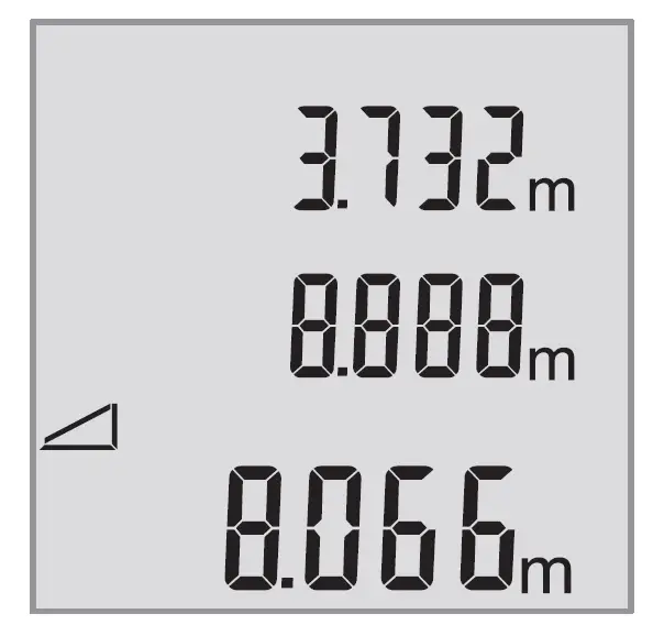
Deleting Measured Values
Briefly pressing the On/Off button 5 [ ] will delete the last measured value in all measuring functions. Repeated brief pressing of the On/Off button 5 [ ] will delete the measured values in reverse order.
Memory Functions
Memory value display: Maximum of 10 values (measured values or end results) can be retrieved. To display memory values, repeatedly press button 4 [Func] until the symbol is shown on the display 1. The number of the memory value is shown at the top of the display, the corresponding memory value is shown at the bottom and the corresponding measuring function is shown on the left. Press button 6 [+] to browse forwards through the saved values. Press button 3 [–] to browse backward through the saved values.
If there is no value available in the memory, “0.000” is shown at the bottom of the display and “0” at the top.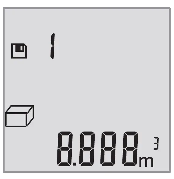
The oldest value is located in position 1 in the memory, while the newest value is in position 10 (when 10 memory values are available). If a further value is saved, the oldest value in the memory is always deleted.
Deleting the Memory
To delete the contents of the memory, press button 4 [Func] so that the symbol appears on the display. Then briefly press the On/Off button 5 [ ] to delete the displayed value.
If the measuring tool is switched off during the memory function, the memory value shown on the display will be deleted.
Adding/Subtracting Values
Measured values or end results can be added or subtracted.
Adding Values
The following example describes the addition of areas: Measure an area as described in section “Area Measurement”, see page 27.
- Press button 6 [+]. The calculated area is shown on the display, and the symbol “+” flashes.
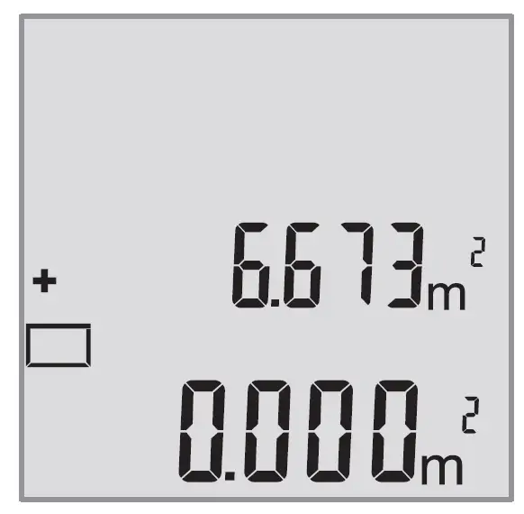
- Press the measuring button 2 [ ] to start another area measurement. Measure the area as described in the section “Area Measurement”, see page 27.
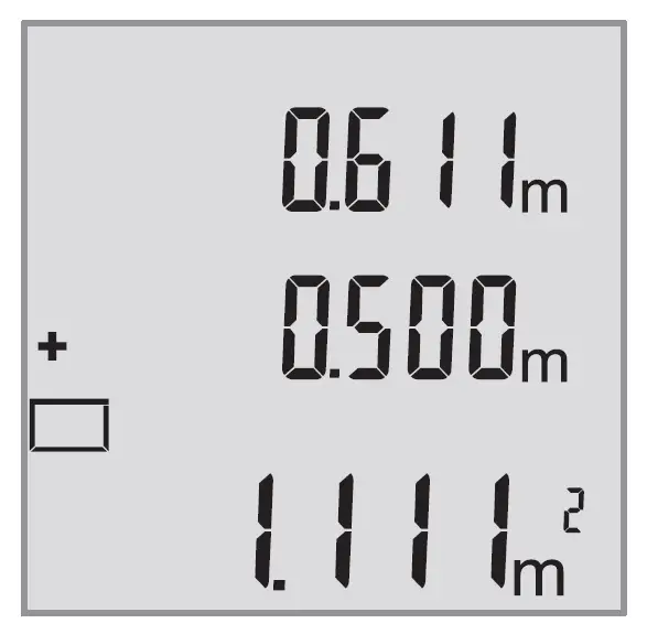
- Press button 6 [+] to calculate the sum. The end result is shown at the bottom of the display.
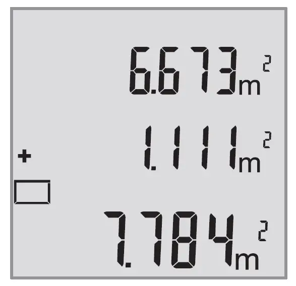
To exit addition, press button 4 [Func].
Subtracting Values
To subtract values, press button 3 [–]. The subsequent steps are the same as for “Adding Values”.
Changing the Unit of Measure
Unit of measure “m” (meters) is set by default. Switch the measuring tool on. Press and hold button 4 [Func] until “ ” and “MFT” flash on the display. “0.000 m” is shown at the bottom of the display. Press button 6 [+] or button 3 [–] to change the unit of measure. “0.000 ft” is shown at the bottom of the display. 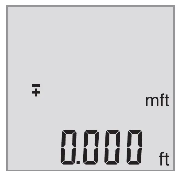
Press button 6 [+] or button 3 [–] to change the unit of measure again. “0’00”” is shown at the bottom of the display.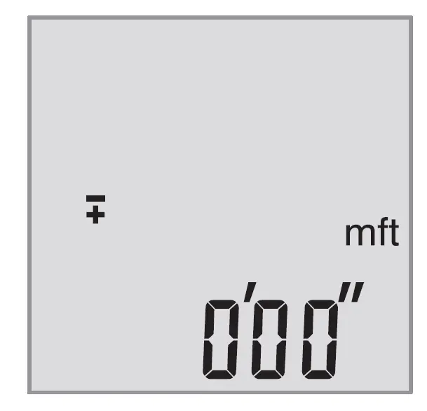
To exit the menu item, press the measuring button 2 [ ] or the On/Off button 5 [ ]. The selected setting remains saved after you switch off the measuring tool.
Switching the Sound On and Off
The sound is switched on by default. Switch the measuring tool on.
- Press and hold button 4 [Func] until “ ” and “MFT” flash on the display. “0.000 m” is shown at the bottom of the display.
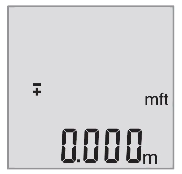
- Press and hold button 4 [Func] again until “ ” and “Sound” flash on the display. “On” is shown at the bottom of the display.

- Press button 6 [+] or button 3 [–] to switch off the sound. “OFF” is shown at the bottom of the display.

- To switch on the sound, press button 6 [+] or button 3 [–] again.
- To exit the menu item, press the measuring button 2 [ ] or the On/Off button 5
- The selected setting remains saved after you switch off the measuring tool.
Display Illumination
The display illumination is continuously switched on. When no button is pressed, the display illumination is dimmed after approx. 10 seconds to preserve the batteries/rechargeable batteries. When no button is pressed after approx. 30 seconds, the display illumination goes out.
Working Advice
General Information
The reception lens 11 and the laser beam outlet 12 must not be covered when taking a measurement.
The measuring tool must not be moved while taking measurements. Therefore, place the measuring tool, as far as this is possible, against or on a firm stop or supporting surface.
Influence Effects on the Measuring Range
The measuring range depends on the lighting conditions and the reflective properties of the target surface. For better visibility of the laser beam in extraneous light, use the laser viewing glasses 14 (accessories) and the laser target plate 13 (accessories) or shade the target area.
Influence Effects on the Measuring Result
Due to physical effects, faulty measurements cannot be excluded when measuring on different surfaces. Included here are:
- Transparent surfaces (e.g., glass, water),
- Reflecting surfaces (e.g., polished metal, glass),
- Porous surfaces (e.g. insulation materials),
- Structured surfaces (e.g., roughcast, natural stone).
If required, use the laser target plate 13 (accessory) on these surfaces. Furthermore, faulty measurements are also possible when sighting inclined target surfaces.
Also, air layers with varying temperatures or indirectly received reflections can affect the measured value.
Accuracy Check of the Distance Measurement
The accuracy of the measuring tool can be checked as follows:
- Select a permanently unchangeable measuring section with a length of approx. 3 to 10 meters; its length must be precisely known (e.g. the width of a room or a door opening). The measurement should be carried out under favorable conditions, meaning, the measuring distance must be indoors and the target surface for the measurement must be smooth and reflect well.
- Measure the distance 10 times in succession.
The deviation of the individual measurements from the average value must not exceed ±4 mm over the entire measuring section in favorable conditions. Record the measurements in order to be able to compare the accuracy at a later date.
Troubleshooting – Causes and Corrective Measures
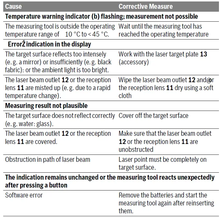
The measuring tool monitors the proper function for each measurement. When a defect is detected, all indicators on the display flash. In this case, or when the corrective measures listed above cannot correct the error, have your dealer forward the measuring tool to an authorized Bosch after-sales service.
Maintenance and Service
Maintenance and Cleaning
- Keep the measuring tool clean at all times.
- Do not immerse the measuring tool in water or other fluids.
Wipe off debris using a moist and soft cloth. Do not use any cleaning agents or solvents. Maintain the reception lens 11 in particular, with the same care as required for eyeglasses or the lens of a camera. After-sales Service and Application Service Our after-sales service responds to your questions concerning the maintenance and repair of your product as well as spare parts.
Exploded views and information on spare parts can also be found under:
www.bosch-pt.com Bosch’s application service team will gladly answer questions concerning our products and their accessories. In all correspondence and spare parts orders, please always include the 10-digit article number given on the nameplate of the product.
Great Britain
Robert Bosch Ltd. (B.S.C.) P.O. Box 98 Broadwater Park North Orbital Road Denham Uxbridge UB 9 5HJ
At www.bosch-pt.co.uk you can order spare parts or arrange the collection of a product in need of servicing or repair.
Tel. Service: (0344) 7360109
E-Mail: [email protected]
Ireland
- Origo Ltd.
- Unit 23 Magna Drive
- Magna Business Park
- City West
- Dublin 24
- Tel. Service: (01) 4666700
- Fax: (01) 4666888
Australia, New Zealand, and Pacific Islands Robert Bosch Australia Pty. Ltd.
- Power Tools
- Locked Bag 66
- Clayton South VIC 3169
- Customer Contact Center
Inside Australia:
- Phone: (01300) 307044
- Fax: (01300) 307045
Inside New Zealand
- Phone: (0800) 543353
- Fax: (0800) 428570
Outside AU and NZ
- Phone: +61 3 9541555 www.bosch.com.au
Republic of South Africa
- Customer service
- Hotline: (011) 6519600
Gauteng – BSC Service Centre 35 Roper Street, New Centre Johannesburg
- Tel.: (011) 4939375
- Fax: (011) 4930126
- E-Mail: [email protected]
- KZN – BSC Service Centre
Unit E, Almar Centre 143 Crompton Street Pinetown
- Tel.: (031) 7012120
- Fax: (031) 7012446
- E-Mail: [email protected]
Western Cape – BSC Service Centre Democracy Way, Prosperity Park Milnerton
- Tel.: (021) 5512577
- Fax: (021) 5513223
- E-Mail: [email protected]
BOSCH PLR 15 Digital Laser Measure

INSTALLATION
Safety Notes
Working safely with the measuring tool is possible only when the operating and safety information are read completely and the instructions contained therein are strictly followed. Never make warning labels on the measuring tool unrecognizable. SAVE THESE INSTRUCTIONS.
Caution – The use of other operating or adjusting equipment or the application of other processing methods than those mentioned here, can lead to dangerous radiation exposure.
- The measuring tool is provided with a warning label (marked with the number 7 in the representation of the measuring tool on the graphics page).
- If the text of the warning label is not in your national language, stick the provided warning label in your national language over it before operating for the first time.
- Do not direct the laser beam at persons or animals and do not stare into the laser beam yourself. This measuring tool produces laser class 2 laser radiation according to IEC 60825-1. This can lead to persons being blinded.
- Have the measuring tool repaired only through qualified specialists using original spare parts? This ensures that the safety of the measuring tool is maintained.
- Do not allow children to use the laser measuring tool without supervision. They could unintentionally blind other persons or themselves.
- Do not operate the measuring tool in explosive environments, such as in the presence of flammable liquids, gases or dust. Sparks can be created in the measuring tool which may ignite the dust or fumes.
Product Description and Specifications
Intended Use
The measuring tool is intended for measuring distances, lengths, heights, and clearances. The measuring tool is suitable for measuring indoors.
Product Features
The numbering of the product features shown refers to the illustration of the measuring tool on the graphic page.
- On/Off switch
- “HOLD” button
- Display
- Battery lid
- Latch of battery lid
- Serial number
- Laser warning label
- Reception lens
- Laser beam outlet
The accessories illustrated or described are not included as standard delivery.
Display Elements
- Battery low indicator
- Temperature warning c Laser switched on
- Measurement hold
- Previous measuring value f Unit of measure
- Current measuring value
Technical Data
| Article number | 3 603 F72 000 |
| Measuring range (typical) | 0.15 15 mA) |
| Measuring accuracy (typical) | ±3.0 mmB) |
| Lowest indication unit | 1 mm |
| Measuring duration typical
maximal |
0.5 s 4 s |
| Operating temperature | 10 °C … + 40 ° C |
| Storage temperature | 20 °C … + 70 ° C |
| Relative air humidity, max. | 90 % |
| Laser class | 2 |
| Laser type | 635 nm, < 1 mW |
| Laser beam diameter (at 25 °C) and at 10 m distance, approx. | 9 mm |
| Batteries | 2 x 1.5 V LR03 (AAA) |
| Battery service life in measuring operation, ap- prox. | 5h |
| Weight according to EPTA-Procedure 01/2003 | 0.1 kg |
| Dimensions | 100x 36 x 23 mm |
- The working range increases depending on how well the laser light is reflected from the surface of the target (scattered, not reflective) and the increased brightness of the laser point to the ambient light intensity (interior spaces, twilight). In unfavourable conditions, e.g., with extreme interior illumination or a badly reflecting surface, the measuring range may be limited.
- In unfavourable conditions, e.g., with extreme interior illumination, badly reflecting surface or the room temperature deviating heavily from 25 °C, the maximum deviation can be up to ±7 mm per 15 m. In favourable conditions, a deviation influence of ±0.05 mm/m must be taken into account. The measuring tool can be clearly identified with the serial number 6 on the type plate.
Assembly
Inserting/Replacing the Batteries
Alkali-manganese batteries are recommended for the measuring tool. To open the battery lid 4, press the latch 5 in the direction of the arrow and remove the battery lid. Insert the batteries. When inserting, pay at-tention to the correct polarity according to the representation on the inside of the battery compartment. When the battery symbol appears for the first time on the display, measurements are still possible for approx. 15 minutes. When the battery symbol flashes, the batteries must be replaced; measurements are no longer possible. Replace all batteries at the same time. Only use same-brand batteries with identical battery capacity.
- Remove the batteries from the measuring tool when not using it for extended periods. When storing for extended periods, the batteries can corrode and discharge themselves
Operation
Initial Operation
- Do not leave the switched on measuring tool unattended and switch the measuring tool off after use. Other persons could be blinded by the laser beam.
- Protect the measuring tool against moisture and direct sunlight.
- Do not subject the measuring tool to extreme temperatures or variations in temperature. As an example, do not leave it in vehicles for a long time. In case of large variations in temperature, allow the measuring tool to adjust to the ambient temperature before putting it into op-eration. In case of extreme temperatures or variations in temperature, the accuracy of the measuring tool can be impaired.
- Avoid heavy impact to or falling down of the measuring tool. After severe exterior effects to the measuring tool, it is recommended to carry out a check (see “Checking the Measuring Tool”, page 21) each time before continuing to work.
Switching On and Off
To switch on the measuring tool, push the On/Off switch 1 toward the rear. When switching on the measuring tool, the laser beam is switched on. The LASER indicator flashes on the display.
To switch off the measuring tool, push the On/Off switch 1 toward the front.
Measuring Procedure
After the measuring tool is switched on, continuous measurement takes place. Aim the laser beam at the target surface. The current measuring value g is displayed in the bottom line of the display (see figure A).  During continuous measurement, the measuring tool can be moved relative to the target, whereby the current measuring value g is updated approx. every 0.5 seconds in the bottom line of the display (see figure B).
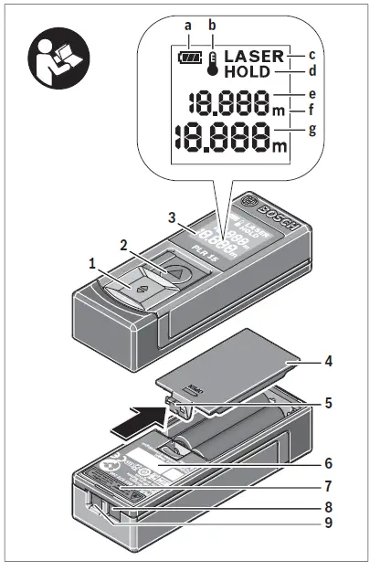
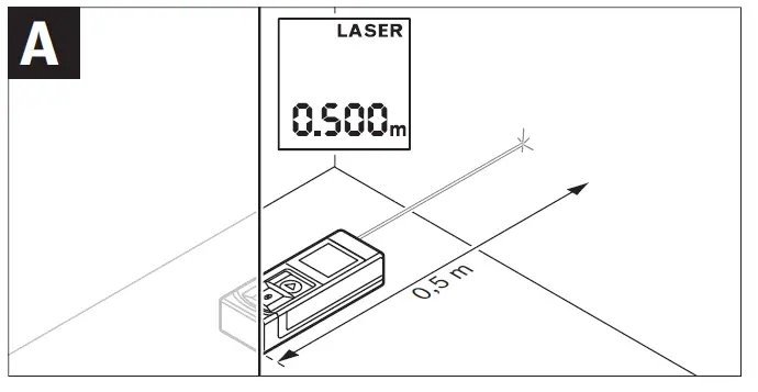 In this manner, as an example, you can move a certain distance away from a wall, while the actual distance can always be read. The LASER indicator flashes on the display. The rear edge of the measuring tool is preset as the reference plane for the measurement. For a wall to wall measurement, as an example, position the measuring tool with its rear edge against the initial wall.
- Do not point the laser beam at persons or animals and do not look into the laser beam yourself, not even from a large distance.
“HOLD” Function 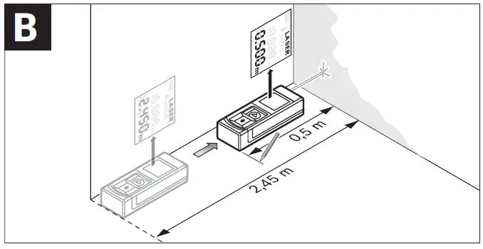
Press the “HOLD” button 2 to stop the measuring procedure. The laser beam is switched off and the HOLD indication appears on the display. The current measuring value is still displayed in the bottom line of the display but is no longer continuously updated. Press the “HOLD” button 2 once more to switch the laser on again. The LASER indicator flashes on the display. The previous measuring value is displayed in the top line. The continuously updated/current measuring value is displayed in the bottom line. Press the “HOLD” button 2 once more to stop the measuring procedure again. The laser beam is switched off and the HOLD indication appears on the display. The previous measuring value is displayed in the top line. The current measuring value is displayed in the bottom line but is no longer continuously updated. When no button on the measuring tool is pressed for approx. 5 minutes, the measuring tool automatically switches off to save the batteries. When a measuring value was held using the “HOLD” function, it is retained after the automatic shut-off. After switching the measuring tool on again by pressing the “HOLD” button 2, the previous measuring value e is indicated in the top line of the display.
Working Advice
General Information
The reception lens 8 and the laser beam outlet 9 must not be covered when taking a measurement. Measurement takes place at the centre of the laser beam, even when tar-get surfaces are sighted at an incline.
Influence Effects on the Measuring Range
The measuring range depends on the light conditions and the reflection properties of the target surface.
Influence Effects on the Measuring Result
Due to physical effects, faulty measurements cannot be excluded when measuring on different surfaces. Included here are:
- Transparent surfaces (e.g., glass, water),
- Reflecting surfaces (e.g., polished metal, glass),
- Porous surfaces (e.g. insulation materials),
- Structured surfaces (e.g., roughcast, natural stone).
Also, air layers with varying temperatures or indirectly received reflections can affect the measured value.
Troubleshooting – Causes and Corrective Measures
The measuring tool monitors the proper function for each measurement. When a defect is detected, all indicators on the display flash. In this case, or when the corrective measures listed above cannot correct the error, have your dealer forward the measuring tool to an authorised Bosch after-sales service.
Checking the Measuring Tool
The accuracy of the measuring tool can be checked as follows:– Select a permanently unchangeable measuring section with a length of approx. 3 to 10 metres; its length must be precisely known (e.g. the width of a room or a door opening). The measurement should be carried out under favourable conditions, meaning, the measuring distance must be indoors and the target surface for the measurement must be smooth and reflect well. Measure the distance 10 times after another. Under favourable conditions, the deviation of the individual measurements from the mean value must not exceed ±3.5 mm (max.) over the complete measuring distance. Log the measurements, so that you can compare their accuracy at a later point of time.
Maintenance and Service
Maintenance and Cleaning
Keep the measuring tool clean at all times. Do not immerse the measuring tool in water or other fluids. Wipe off debris using a moist and soft cloth. Do not use any cleaning agents or solvents. Maintain the reception lens 8 in particular, with the same care as required for eye glasses or the lens of a camera. If the measuring tool should fail despite the care taken in manufacturing and testing procedures, repair should be carried out by an authorised af-ter-sales service centre for Bosch power tools. Do not open the measuring tool yourself. For repairs, send in the measuring tool in.
After-sales Service and Application Service
Our after-sales service responds to your questions concerning maintenance and repair of your product as well as spare parts. Exploded views and information on spare parts can also be found under:
www.bosch-pt.com Bosch’s application service team will gladly answer questions concerning our products and their accessories. In all correspondence and spare parts orders, please always include the 10-digit article number given on the type plate of the measuring tool.
Great Britain
- Robert Bosch Ltd. (B.S.C.)
- P.O. Box 98
- Broadwater Park
- North Orbital Road
- Denham
- Uxbridge
- UB 9 5HJ
- Tel. Service: (0844) 7360109
- Fax: (0844) 7360146
- E-Mail: [email protected]
Ireland
- Origo Ltd.
- Unit 23 Magna Drive
- Magna Business Park
- City West
- Dublin 24
- Tel. Service: (01) 4666700
- Fax: (01) 4666888
Australia, New Zealand and Pacific Islands Robert Bosch Australia Pty. Ltd.
- Power Tools
- Locked Bag 66
- Clayton South VIC 3169
- Customer Contact Center
- Inside Australia:
- Phone: (01300) 307044
- Fax: (01300) 307045
- Inside New Zealand:
- Phone: (0800) 543353
- Fax: (0800) 428570
- Outside AU and NZ:
- Phone: +61 3 95415555
- www.bosch.com.au
Republic of South Africa Customer service’
- Hotline: (011) 6519600
Gauteng – BSC Service Centre
- 35 Roper Street, New Centre Johannesburg
- Tel.: (011) 4939375
- Fax: (011) 4930126
- E-Mail:[email protected]
KZN – BSC Service Centre
- Unit E, Almar Centre
- 143 Crompton Street
- Pinetown
- Tel.: (031) 7012120
- Fax: (031) 7012446
- E-Mail:[email protected]
Western Cape – BSC Service Centre
- Democracy Way, Prosperity Park
- Milnerton
- Tel.: (021) 5512577
- Fax: (021) 5513223
- E-Mail:[email protected]
Bosch Headquarters
- Midrand, Gauteng
- Tel.: (011) 6519600
- Fax: (011) 6519880
- E-Mail:[email protected]
Disposal
Measuring tools, accessories and packaging should be sorted for environmental-friendly recycling. Do not dispose of measuring tools and batteries/rechargeable batteries into household waste! Only for EC countries:
]]>Truvo
![]()
![]()
![]()
1 609 92A 6H5 (2021.06)
Safety Instructions
All instructions must be read and observed. The safeguards integrated into the measuring tool may be compromised if the measuring tool is not used in accordance with these instructions. STORE THESE INSTRUCTIONS IN A SAFE PLACE.
- Have the measuring tool serviced only by a qualified specialist using only original replacement parts? This will ensure that the safety of the measuring tool is maintained.
- Do not use the measuring tool in explosive atmospheres which contain flammable liquids, gases or dust. Sparks may be produced inside the measuring tool, which can ignite dust or fumes.
- The measuring tool may not be 100 % accurate for technological reasons. To eliminate hazards, familiarise yourself with further sources of information, such as building plans and photographs taken during construction, etc. before carrying out any drilling, sawing, or routing work on walls, ceilings, or floors. The accuracy of the measuring tool may be affected by environmental influences, such as the level of humidity or there being other electronic devices nearby. The structure and condition of the walls (e.g. damp, building materials containing metal, electrically conductive wallpaper, insulating materials, tiles) and the number, type, size, and position of the objects may distort the measuring results.
- Make sure that you are properly earthed when taking measurements. If you are not properly earthed (e.g. by wearing insulating footwear or by standing on a ladder), it will not be possible to locate live cables.
- If there are gas pipes in the building, check to ensure that none of them have been damaged after completing any work on walls, ceilings or floors.
- Live wires can be detected more easily when power consumers (e.g. lamps, appliances) are connected to the wire being sought and switched on. Switch off power consumers and make sure that live cables are de-energized before drilling, sawing or milling into walls, ceilings or floors. After performing any kind of work, check to ensure that objects placed on the base material are not live.
- When attaching objects to dry walls, and in particular when attaching them to the substructure, check to ensure that both the wall and the fastening materials have a sufficient load-bearing capacity.
Product Description and Specifications
Please observe the illustrations at the beginning of this operating manual.
Intended Use
The measuring tool is intended for the detection of metal (ferrous and nonferrous metals, e.g. reinforcing steel) and live wires in walls, ceilings and floors.
The measuring tool is suitable for indoor use.
Product features
The numbering of the product features shown refers to the illustration of the measuring tool on the graphic page.
- Gripping surface
- On/off switch
- Indicator light
- Left-hand and right-hand marking aids
- Top marking aid
- Sensor area
- Serial number
- Battery compartment cover
- Battery compartment cover locking mechanism
Technical data
| Digital detector | Truvo 3 603 F68 2.. |
| Article number | |
| Max. detection depth | |
| – Ferrous metals | 70 mm |
| – Non-ferrous metals (copper pipe) | 60 mm |
| – Single-phase live cables (110-240 V, 50-60 Hz, with voltage applied)8) | 50 mm |
| Calibration | Automatic |
| Operating temperature | 0°C to +40°C |
| Storage temperature | -20°C to +70°C |
| Operating frequency range | 50 ± 2 kHz |
| Max. magnetic field strength (at 10 m) | 42 dBpA/m |
| Max. altitude | 2000 m |
| Relative air humidity | 30-80 % |
| Pollution degree according to IEC 61010-1 | 2C) |
| Batteries | 3 x 1.5 V LR3 (AAA) |
| Approx. operating time | 5 h |
| Weight according to EPTA-Procedure 01:2014 | 0.15 kg |
Weight according to EPTA-Procedure 01:2014 0.15 kg
A) Depends on the material and size of the objects, as well as the material and condition of the substrate
B) Lower detection depth with non-live wires
C) Only non-conductive deposits occur, whereby occasional temporary conductivity caused by condensation is expected.
The serial number (7) on the type plate is used to clearly identify your measuring tool.
- The accuracy and detection depth of the measuring result may be negatively affected if the condition of the substrate is unfavorable.
Assembly
Inserting/changing the batteries
It is recommended that you use alkaline manganese batteries to operate the measuring tool.
To open the battery compartment cover (8), press the locking mechanism (9) and lift open the battery compartment cover. Insert the batteries.
When inserting the batteries, ensure that the polarity is correct according to the illustration on the inside of the battery compartment.
Always replace all the batteries at the same time. Only use batteries from the same manufacturer and which have the same capacity.
- Take the batteries out of the measuring tool when you are not using it for a prolonged period of time. The batteries can corrode and self-discharge during prolonged storage in the measuring tool.
Operation
- Protect the measuring tool from moisture and direct sunlight.
- Do not expose the measuring tool to any extreme temperatures or variations in temperature. In case of large variations in temperature, leave the measuring tool to adjust to the ambient temperature before switching it on. The precision of the measuring tool may be compromised if exposed to extreme temperatures or fluctuations in temperature.
- Avoid hard knocks to the measuring tool or dropping it. After severe external influences and in the event of abnormalities in the functionality, you should have the measuring tool checked by an authorized Bosch after-sales service agent.
- Certain ambient conditions fundamentally impair the measuring results. These include, e.g. the proximity of devices that generate strong electric, magnetic or electromagnetic fields, moisture, metal building materials, foil-laminated insulation materials, or conductive wallpaper or tiles. Therefore, also refer to other information sources (e.g. construction plans) before drilling, sawing, or routing into walls, ceilings, or floors.
- Hold the measuring tool by the intended gripping surface (1) only, so as not to influence the measurement.
- Do not attach any stickers or labels to the sensor area (6) on the rear of the measuring tool. Metal labels in particular will affect measuring results.
 Do not wear gloves when taking measurements and make sure that you are properly earthed. If you are not properly earthed, the identification of live wires may be impaired.
 When taking measurements, avoid devices that emit strong electric, magnetic or electromagnetic fields. If possible, deactivate all tools whose radiation could interfere with the measurement and switch off the corresponding functions or tools.
- Starting Operation
Switching on/off
- Before switching on the measuring tool, ensure that the sensor area (6) is dry. If necessary, use a cloth to dry the measuring tool.
- If the measuring tool has been exposed to a significant change in temperature, leave it to adjust to the ambient temperature before switching it on.
![]() To switch on the measuring tool, push the on/off switch (2) down.
To switch on the measuring tool, push the on/off switch (2) down.
The measuring tool carries out a short self-check and calibrates itself automatically. Once the indicator light (3) turns green, the measuring tool is ready to use.
![]() To switch off the measuring tool, push the on/off switch (2) up.
To switch off the measuring tool, push the on/off switch (2) up.
If no measurement takes place for approx. 10 minutes, the measuring tool automatically switches off to save the batteries.
Note: When the measuring tool has switched off automatically, the on/off switch (2) will still be in the “on” position. To switch the measuring tool on again, first, switch it off and then switch it on again.
How it Works
The measuring tool checks the substrate of the sensor area (6) up to the maximum detection depth.
Metal objects and live cables are automatically searched for during each measurement.
![]()
Always move the measuring tool in a straight line in a lateral direction over the substrate, applying light pressure, without lifting it off or changing the pressure. Hold the measuring tool by the gripping surface (1) with an even grip and do not touch the sensor area (6) while taking measurements.
| Indicator light and audio signal | Meaning |
| Green + silent | No object is within the sensor range |
| Yellow + silent | – Metal object near the sensor or – Small or deep-lying metal object is within the sensor range or – Sensor interference due to the unfavorable nature of the wall |
| Red + continuous tone | The metal object is within the sensor range |
| Red flashing + pulsating sound | Live cable is within the sensor range |
Objects are only displayed roughly the first time you move over them. Move the measuring tool several times over the same surface in order to locate the object precisely.
The detection depth of the measurement depends on the material and size of the objects, as well as the material and condition of the substrate, and may be less than the maximum detection depth.
- Before drilling, sawing or routing into walls, refer to other sources of information to ensure that you eliminate hazards. Since the measuring results can be influenced by ambient conditions or the nature of the wall, there may be a hazard even though no audio signal is emitted and the indicator light (3) lights up green.
Searching for Metal Objects
When approaching a metal object, the indicator light (3) first lights up yellow, then changes to red and an audio signal is emitted. The pitch of the audio signal increases as the metal object is approached. If the metal object is below the center of the sensor range (6), the pitch will be at its highest.
- Even when the indicator light is yellow, there may be a metal object below the sensor range. Small or deep-lying metal objects are near the sensor, or the nature of the wall affects the measuring result.
Searching for Live Cables
The measuring tool displays single-phase live cables (110−240 V, 50−60 Hz). Other cables (multi-phase electricity cables, DC, higher/lower frequency or voltage), as well as non-live cables, cannot be reliably detected, but they may be displayed as metal objects. Preparing to take measurements and features of the measuring process:
– The cable must be live. You should therefore connect electricity consumers (e.g. lights, appliances) to the electricity cable you are trying to find. Switch on the electricity consumers to ensure that the electricity cable is live.
– The 50–60 Hz signal from the electric cable must be able to reach the measuring tool. If the cable is in damp walls (e.g. due to high humidity), behind metallic foils (e.g. from thermal insulation) or in an empty metal pipe, the signal will not reach the measuring tool and you will not be able to find the cable.
If the indicator light (3) lights up yellow or red over a larger range, then the material is electrically shielded and the search for living ables is not reliable.
–The measuring tool must be sufficiently earthed. To do this, hold it firmly (without gloves) by the gripping surface (1). Make sure that you are in good contact with the floor. Insulating shoes, ladders or platforms may compromise your contact with the floor. The floor must also be earthed in order for live cables to be detected.
– The 50–60 Hz signal from the electric cable must be stronger along the cable than in its immediate vicinity. If the wall is very dry or poorly earthed, the signal will be the same strength throughout the wall.
This will result in the measuring tool indicating that it has found a signal over a large area, but it will not be able to detect the exact location of the cable. In this instance, it may be helpful to place your free hand on the wall 20−30 cm from the measuring tool in order to conduct the signal away from the wall.
If a live cable is found, the indicator light (3) flashes red and a pulsating audio signal will sound at a fast rate.
Working Advice
Marking objects
If required, detected objects can be marked. Perform a measurement as usual.
Once you have found the boundaries or the center of an object, mark the sought location at the top marking aid (5) and the side marking aid (4). Connect the points with a vertical and horizontal line. The boundary or the center of the object is located where the lines intersect.
Recalibration
Manually recalibrate the measuring tool if the indicator light (3) continues to light up yellow or red even though there is no metal near the measuring tool.
– Switch on the measuring tool using the on/off switch (2).
– Remove a battery from the measuring tool whilst it is switched on.
– Switch off the measuring tool using the on/off switch (2) after the battery has been removed.
– Reinsert the battery into the measuring tool. Ensure that the polarity is correct.
– Remove all objects near the measuring tool (including watches or metal rings) and hold the measuring tool in the air.
– Switch the measuring tool on and off again within 3 s using the on/off switch (2). The indicator light (3) will flash red slowly for the 3 s to indicate readiness for calibration.
– Switch the measuring tool back on within 0.5 s. The calibration will start and take roughly 6 s. During calibration, the indicator light (3) flashes green at a fast rate. Once the indicator light lights up green continuously, the calibration is complete and the measuring tool is ready to use.
Note: If the sequence of switching off and switching on again is not observed, calibration will not take place. The indicator light (3) continues to light up yellow or red even though there is no metal nearby. In this case, repeat the calibration in the exact same way.
Errors – Causes and Corrective Measures
| Cause | Corrective measures |
| Measuring results inaccurate/implausible | |
| Interfering objects are within the sensor range (6) | Remove all interfering objects (e.g. watches, bracelets, rings, etc.) from within range of the sensor (6). Do not hold the measuring tool close to the sensor. |
| Auto-calibration not successful | Manually recalibrate the measuring tool. |
| The indicator light does not light up. | |
| The measuring tool has switched off automatically. | Switch the measuring tool off and on again. |
| Batteries drained | Change the batteries. |
| Indicator light lights up green/yellow/red in an uncoordinated manner. | |
| Interference from electric, magnetic or electromagnetic
fields |
If possible, deactivate all tools whose radiation could interfere with the measurement and switch off the corresponding functions or tools. |
| Indicator light flashes continuously, alternating green/yellow/red. | |
| Measuring tool faulty | Send the measuring tool to an authorized Bosch after-sales service center. |
Error when searching for and indicating metal
| Cause | Corrective measures |
| Indicator light lights up yellow or red even though there is no metal nearby. | |
| Ambient temperature too high/too low | Only use the measuring tool in the operating temperature range. |
| Cause | Corrective measures |
| Strong temperature variation | Allow the measuring tool to reach the correct temperature. |
| Auto-calibration not successful | Manually recalibrate the measuring tool. |
| Indicator light lights up the wall. yellow or red over a large measuring range on | |
| Many metal objects spaced closely together | Be sure to listen to the pitch of the audio signal in order to distinguish between individual metal objects. Metal objects spaced too closely together cannot be detected separately. |
| Building materials containing metal or reinforcing steel in concrete | In the presence of metallic building materials (e.g. foil-laminated insulation materials, heat conduction plates), reliable detection is not possible. |
| Solid metal objects on the back of the wall | In the presence of solid metal objects (e.g. radiators), reliable detection is not possible. |
| Auto-calibration not successful | Manually recalibrate the measuring tool. |
| Metal object not found. | |
| Metal object is too deep or too small. | The detection depth depends on the building material and on the object and maybe less than the maximum detection depth. |
Error when searching for and indicating live cables
| Cause | Corrective measures |
| The indicator light flashes red over a large measuring range on the wall. | |
| Insufficient earthing of the wall | Touch the wall with your free hand at a distance of 20−30 cm from the measuring tool in order to earth the wall. |
| Live cable not found. | |
| No/unusual voltage in the cable | Apply voltage to the cable, e.g. by turning on the corresponding light switches. It is not possible to reliably detect multi-phase electricity cables |
Maintenance and Service
Maintenance and Cleaning
- Check the measuring tool before each use. If the measuring tool is visibly damaged or parts have become loose inside the measuring tool, the safety function can no longer be ensured. Always keep the measuring tool clean and dry to ensure optimum, safe operation. Never immerse the measuring tool in water or other liquids. Wipe off any dirt using a dry, soft cloth. Do not use any detergents or solvents.
After-Sales Service and Application Service
Our after-sales service responds to your questions concerning maintenance and repair of your product as well as spare parts. You can find explosion drawings and information on spare parts at: www.bosch-pt.com
The Bosch product use advice team will be happy to help you with any questions about our products and their accessories.
In all correspondence and spare parts orders, please always include the 10‑digit article number given on the nameplate of the product.
Great Britain
Robert Bosch Ltd. (B.S.C.)
P.O. Box 98
Broadwater Park
North Orbital Road
Denham Uxbridge
UB 9 5HJ
At www.bosch-pt.co.uk you can order spare parts or arrange the collection of a product in need of servicing or repair.
Tel. Service: (0344) 7360109
E-Mail: [email protected]
You can find further service addresses at: www.bosch-pt.com/serviceaddresses
Disposal
Measuring tools, accessories and packaging should be recycled in an environmentally friendly manner.
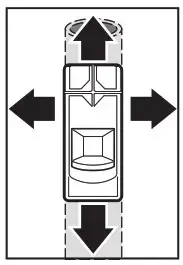 Do not dispose of measuring tools or batteries with household waste.
Only for EU countries:
According to the Directive 2012/19/EU, measuring tools that are no longer usable, and according to the Directive 2006/66/EC, defective or used battery packs/batteries, must be collected separately and disposed of in an environmentally correct manner.
Robert Bosch Power Tools GmbH
70538 Stuttgart
GERMANY
www.bosch-pt.com
![]()
Explanation of symbols and safety information
Key to symbols
Warnings
In warnings, signal words at the beginning of a warning are used to indicate the type and seriousness of the ensuing risk if measures for minimising danger are not taken.
The following signal words are defined and can be used in this document:
DANGER indicates a hazardous situation which, if not avoided, will result in death or serious injury
WARNING indicates a hazardous situation which, if not avoided, could result in death or serious injury.
CAUTION indicates a hazardous situation which, if not avoided, could result in minor or moderate injury
NOTICE is used to address practices not related to personal injury.
Important information
The info symbol indicates important information where there is no risk to people or property.
Additional symbols
| Symbol | Meaning |
| ▶ | a step in an action sequence |
| → | a reference to a related part in the document |
| • | a list entry |
| – | a list entry (second level) |
Safety information
CAUTION:
Risk of electric shock!
When using electrical appliances, safety precautions to reduce the risk of fire, electric shock or injury to persons should be followed, including:
READ ALL INSTRUCTIONS BEFORE USING THIS WATER HEATER.
- This water heater must be grounded. Connect only to properly grounded outlet. See “GROUNDING INSTRUCTIONS” found on “INSTALLATION INSTRUCTIONS” .
- Install or locate this water heater only provided installation instructions.
- Use this water heater only for its intended use as described in this manual.
- The models ES2.5 and ES4 come equipped with a power cord. Do not use an extension cord. If no outlet is available adjacent to the water heater, contact a qualified electrician to have one properly installed near the heater.
The model ES8 must be hard-wired. See installation instructions. - As with any appliance, close supervision is necessary when used by children.
- Do not operate this water heater if it is has a damaged cord or plug, if it is not working properly, or if it has been damaged or dropped.
- This water heater should be serviced only by qualified service personnel.
Contact a service person for examination, repair or adjustment. - Failure to inspect the anode rod at least once a year could cause the tank to fail and leak. This condition is not covered under the manufacturer’s warranty.
- Any water heater should be installed in such a manner that if it should leak, the resulting flow of water will not cause damage to the area in which it is installed. National Plumbing codes require a drain pan for any water heater installation. Failure to install one is the sole responsibility of owner and/or installer. Reference UPC 2006 (Uniform Plumbing Code) Section 508.1, or IPC 2006 (International Plumbing Code) Section 504.7.
NOTICE
- The installer should review the contents of this manual with the owner upon completion of installation, and the manual should be left with the owner and placed in a location close to the installation.
- The manufacturer cannot be responsible for the damages caused by improper installation or by failure to follow instructions in this manual. Comply with the installation instructions before completing electric connection.
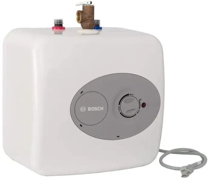
DANGER:
Hydrogen gas can be produced in a hot water system served by this heater that has not been used for a long period of time (generally 2 weeks or more). Hydrogen gas is extremely flammable. To reduce the risk of injury under these conditions, it is recommended that the hot water faucet be opened for several minutes at the kitchen sink before using any electrical appliance connected to the hot water system. If hydrogen gas is present, there will probably be an unusual sound such as air escaping through the pipe as the water begins to flow. There should be no smoking or open flame near the faucet at the time it is open.
CAUTION:
Any water heater should be installed in such a manner that if it should leak, the resulting flow of water will not cause damage to the area in which it is installed. National
Plumbing codes require a drain pan for any water heater installation. Failure to install one is the sole responsibility of owner and/or installer. Reference UPC 2006 (Uniform Plumbing Code) Section 508.1, or IPC 2006 (International Plumbing Code) Section 504.7.
CAUTION:
Prior to connecting the power supply, ensure tank is full of water and system is purged of air.
NOTICE:
Tank failure due to neglecting to maintain the anode rod is not covered under warranty (see Section 5 Maintenance).
Information about the product
Models overview
Models ES2.5 and ES4
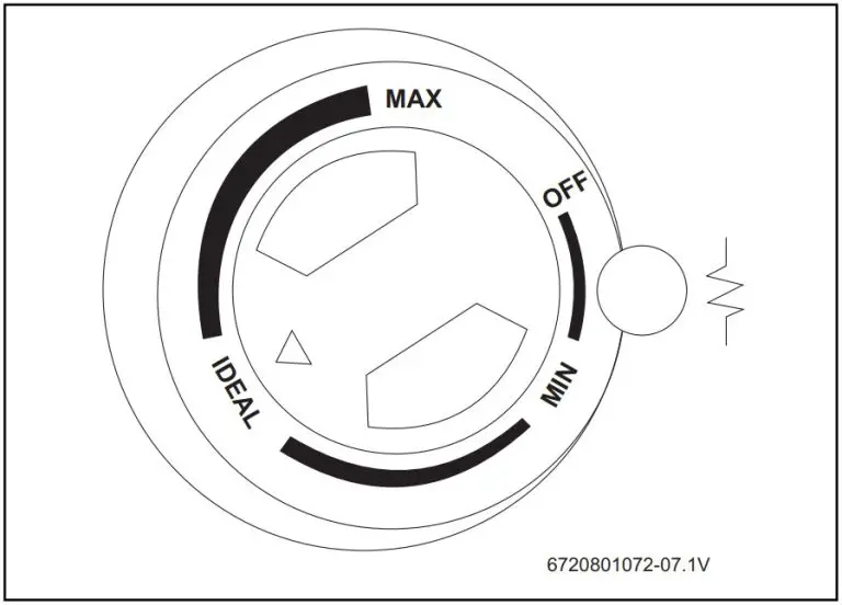
- Temperature & pressure relief valve, ¾ NPT male
- Cold water inlet ½ NPT male
- Thermostat
- Temperature & pressure relief valve discharge line to drain
- ¾ NPT female tapping for relief valve
- Hot water outlet ½ NPT male
Models ES8 (Horizontal installation)
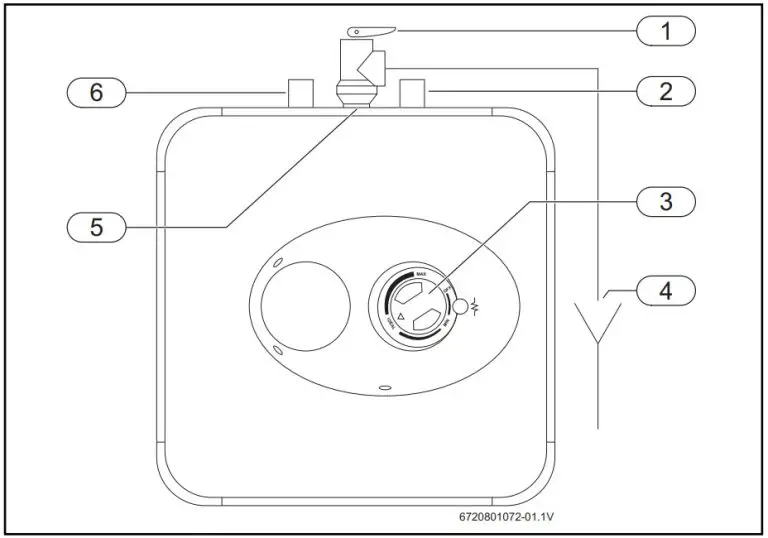
- Temperature & pressure relief valve, ¾ NPT male
- Cold water inlet ¾ NPT male
- Thermostat
- Temperature & pressure relief valve discharge line to drain
- ¾ NPT female tapping for relief valve
- Hot water outlet ¾ NPT male
- ¾ NPT male plug
- ¾ NPT female tapping for tap
Models ES8 (Vertical installation)
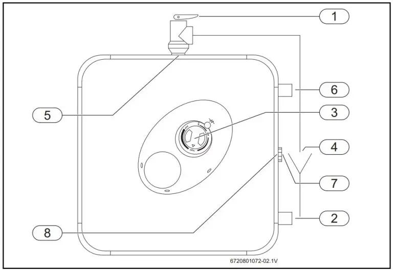
- Temperature & pressure relief valve, ¾ NPT male
- Cold water inlet ½ NPT male
- Thermostat
- Temperature & pressure relief valve discharge line to drain
- ¾ NPT female tapping for relief valve
- Hot water outlet ½ NPT male
- Hot water outlet ½ NPT male
- Hot water outlet ½ NPT male
Dimensions
- Models ES2.5 and ES4 (Vertical installation only)
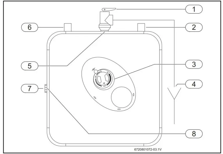
- Models ES8 (Horizontal installation only)
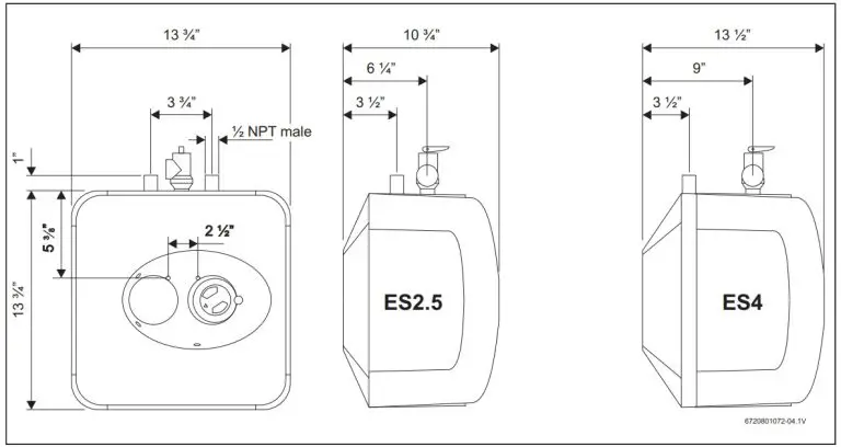
- Models ES8 (Vertical installation only)

Technical data
| Technical data | Units | ES 2.5 | ES 4 | ES 8 |
| Capacity | gallons | 2.7 | 4.0 | 7.0 (Hor.) / 5.1 (Vert.) |
| Voltage | VAC | 110/120 for each model | ||
| Power at 120 VAC | Watts | 1440 | ||
| Maximum water pressure | psi | 150 | ||
| Weight (empty) | Lbs | 15.5 | 17.3 | 29.5 |
| Amperage | Amps | 12.0 for each model | ||
| Phases | 1 | |||
| Temperature range | °F | 65 – 145 | ||
| Recovery rate | gallons/hour | 6.8 | ||
Installation instructions
The ES2.5 and ES4 water heaters are designed to be installed under the sink.
Mounting the heater
Wall mounting
NOTICE:
The ES2.5 and ES4 water heaters come equipped with a power cord.
- Ensure the circuit breaker supplying the electrical outlet for the water heater is properly sized to handle the load of both the water heater and another appliance (e.g. dishwasher).
See Table 2 for water heater electrical specifications. - Fasten the supplied mounting bracket to the wall.
NOTICE:
Material damages!
- Use screws that are suitable for the wall material and the weight of the heater.
- Hang the water heater on the bracket.
- Tug down wards on the heater to ensure that both “fingers” of the bracket are seated in the mounting slots.
Floor mounting
- Heater can sit on floor.
Pipe connections
- Connect the cold water inlet pipe to the inlet tapping (marked with a blue ring).
- Ensure a isolation valve is installed on the cold water supply to the water heater.
- Connect the hot water outlet pipe to the outlet tapping (marked with a red ring).
The model ES8 can be piped horizontally from the side or vertically from the top.
Horizontal installation – ES8 Model Only
If you wish to install the unit horizontally, with the piping connections on the right side:
- Install supplied brass plug into tap between hot and cold water connections.
- The supplied Temperature and Pressure Relief Valve will need to be installed on top. See location of T&P relief valve.
Vertical installation
If you wish to install the unit vertically, with the piping connections on top:
- Install supplied brass plug into tap on side of water heater.
- The supplied Temperature and Pressure Relief Valve will need to be installed on top. See location of T&P relief valve
CAUTION:
To reduce the risk of excessive pressures and temperatures in this water heater:
- Install the supplied temperature and pressure protective equipment required by local codes but not less than a combination temperature and pressure relief valve certified by a nationally recognized testing laboratory that maintains periodic inspection of production of listed equipment or materials, as meeting the requirements for Relief Valves and Automatic Gas Shut-off Devices for Hot Water Supply Systems, ANSIZ21.22.
The supplied temperature and pressure relief valve is marked with a maximum set pressure (150 psi) that does not exceed the marked maximum working pressure of the water heater.
- Install the valve in the opening provided and marked for this purpose in the water heater.
- Orient it or provide tubing so that any discharge from the valve will exit within 6 inches above, or at any distance below, the structural floor, and cannot contact any live electrical part. The discharge opening must not be blocked or reduced in size under any circumstances.
National Plumbing codes may require a drain pan for the water heater installation. Failure to install one is the sole responsibility of owner and/ or installer. Reference UPC (Uniform Plumbing Code), or IPC (International Plumbing Code).
Closed system thermal expansion
Periodic discharge of the temperature and pressure relief valve or failure of the element gasket may be due to thermal expansion in a closed water supply system. The water utility supply meter may contain a check valve, back flow preventer or water pressure reducing valve which will create a closed water system.
During the heating cycle of the water heater, the water expands causing pressure inside the water heater to increase. The temperature and pressure relief valve may discharge hot water under these conditions which results in a loss of energy and a build-up of lime on the relief valve seat.
To prevent this from happening, there are two recommendations:
Install a diaphragm-type expansion tank that is suitable for potable water on the cold water supply line. A minimum 0.5 gallon expansion tank should be used.
Contact the local water supplier or plumbing inspector for information on how to control this situation. Do not plug the temperature and pressure relief valve.
Electrical connections
The ES8 model must be hard wired. As per the National Electric Code the ES8 needs to be wired with 12 GA. wire to a 20 amp branch circuit.
- Unscrew the junction box cover and remove it.
- Insert 12 AWG through conduit into junction box and secure with conduit strain relief (not supplied).
- Connect the wires and screw on the cover of the junction box.
- Make appropriate wiring connections to the water heater per the National Electric Code.
The unit must be grounded with supplied grounding cable inside junction box.
- Secure junction box cover once wiring connections have been made
When the ES8 is not within sight of the electrical circuit breakers, a circuit breaker lockout or additional local means of disconnection for all non grounded conductors must be provided that is within sight of the appliance. [REF NEC 422.31].
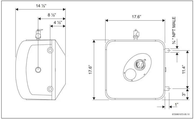
- Cable housing (internal to the unit)
- Wiring
- Protection ring for wiring.
- Additional grounding cable AWG16 (minimum length 152mm)
- Junction box left cover
- Nº3 self tapping screw for junction box covers fixing (with lock washer or serrated head)
- Junction box right cover
- Nº1 self tapping screw for grounding (with lock washer or serrated head)
- Nº4 screws for junction box fixing
- Junction box
Use
Starting and testing
CAUTION:
DO NOT supply power to water heater until filled with water.
To fill the heater:
- Open supply valve for water heater to fill with water.
- Open hot water tap(s) supplied by the water heater to purge air out of the system. Once air is purged, close hot water tap.
- Visually check for any leaks.
Turning heater on
For models which are not fitted with a switch:
- Supply power to the water heater by plugging in the power cord (models ES2.5, ES4) or turning on the circuit breaker (model ES8). If the light does not come on, turn the control knob in a clockwise direction.
The light will come on until water temperature has reached the thermostat temperature setting. The light will come back on any time the water temperature inside the tank drops below the thermostat setting.
Temperature setting
The temperature of the hot water is adjusted by rotating the knob M located on the front cover. Temperature range is 65 -145 °F.
- Turn the knob clockwise to increase temperature.
- Turn the knob counter-clockwise to decrease temperature.
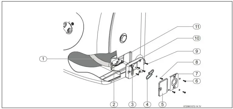
Maintenance
CAUTION:
Do not attempt to repair this water heater yourself. Call a service person for assistance. Always turn off the power supply to the heater prior to servicing or draining the heater.
Periodic maintenance
For most of these operations, the water will have to be drained from the heater. For all of these operations the cord should be disconnected (ES2.5 and ES4 only) and the front cover removed.
Removing the cover
- Pry off the round cover plate [V] from its right hand edge [W] with a small flat-head screwdriver.
- Remove the Phillips screw revealed beneath the round cover plate.
- The cover [C] can now be removed by pulling out its left hand edge. When reassembling, work in the opposite way being careful to insert the tongue of the cover into the slot.
Draining the heater
If the heater has been installed with flexible hoses:
- Shut off the power supply.
- Turn the heater upside down over a sink to drain the water out of it.
-or
If the heater has been installed with rigid piping:
- Siphon the water out through any (lower) service valve on the (inlet side).
- Keep a hot water faucet open while siphoning the water out.
Inspecting the anode rod
The purpose of the anode rod is to protect the tank against corrosion. It is critical that the anode rod be inspected once a year to determine whether it requires replacement. To access the anode rod, the heating element must be removed (see Section 5.4 Removing the heating element). Upon inspection, the anode rod surface should appear smooth. If the rod surface appears pitted, bumpy, rusty, or if the rod is missing completely, then it must be replaced.
To access the anode rod:
- Remove the heating element (see Section 5.4 Removing the heating element).
Original anode rod sizes
- ES2.5, ES4: length 6½”, diameter 5/8″
- ES8:length 8¼”, diameter 5/8″
Certain installations may require more frequent replacement of the anode rod:
- recirculation applications;
- poor water quality;
- galvanic/electrolytic corrosion
- high flow applications
In the event of poor water quality, Bosch recommends consulting a local water treatment professional for water treatment options. Always ensure the water heater is grounded.
Models ES2.5 and ES4 must be connected only to a properly grounded outlet. Damage resulting from poor water quality or failure to replace the anode rod is not covered under the manufacturer’s warranty. For additional questions, please call Bosch Technical Service.
Removing the heating element
- Turn off power supply and drain the heater (see previous section).
- Remove the front cover plate, disconnect terminals X, Y andT.
- Unscrew the 4 heating element retaining nuts F.
- Remove thermostat temperature sensor from well [B] located on the element assembly.
- Remove the element G.
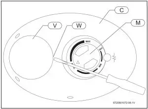
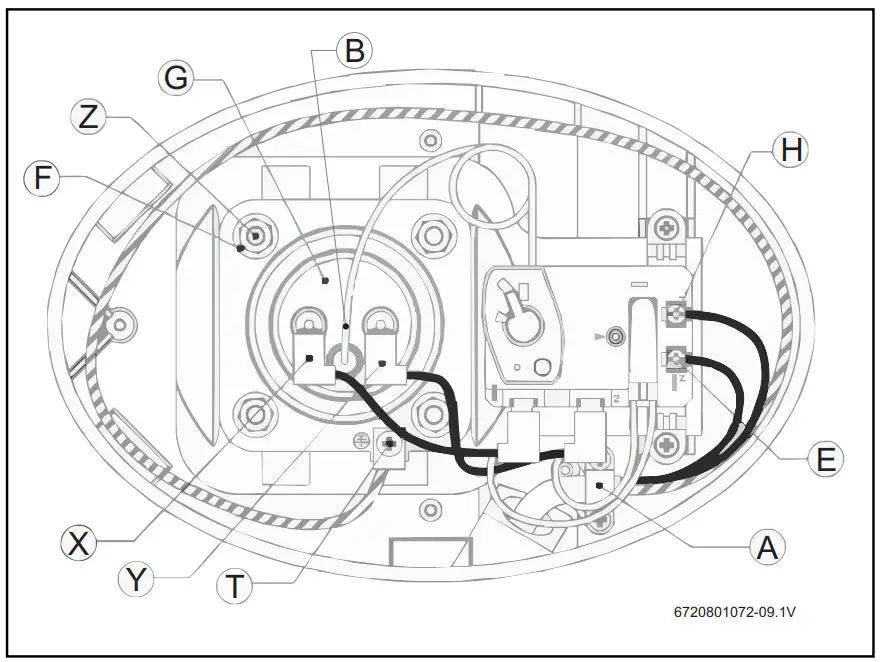
Descaling the heating element
Scale deposits can affect the heating capability of the element.
Heavy scale can even cause damage to the element. The element can be descaled either chemically or manually:
- Soak the element in white vinegar or other descalingsolution.
- Once descaled, rinse well with fresh water, to which you should add some baking soda,
-or
- Once the element has dried, use a soft brush (non metallic to prevent damaging the stainless steel sheath) on element.
- Brush the dried mineral off.
- Reinstall the element with gasket and make the wire connections.
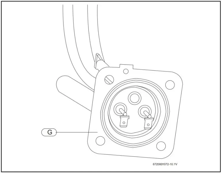
NOTICE
Make sure the tank has been refilled with water before restoring power.
Replacement of parts
Changing the anode rod
- Turn off the power supply and drain the heater (see Draining the Heater).
- Remove heating element (see previous section).
- Unscrew anode rod from threaded connection.
- Remove and replace the anode rod .
- Reinstall heating element.
- Refill tank with water before restoring power
Changing the heating element
- Turn off power supply and drain the heater (see Draining the Heater).
- Remove the heating element (see section on Removing the Heating Element)
- Install new element with gasket, making sure the gasket and element are positioned correctly. Tighten the retaining nuts and make the wire connections.
- Ensure that the thermostat temperature sensor is inserted into the well located on the element assembly and secured with black rubber grommet.
- Refill tank with water before restoring power.
Changing the thermostat
- Turn off power supply.
- Disconnect the 2 wire connectors on thermostat.
- Loosen the two brass screws at right side of thermostat and pull wires out.
- Remove thermostat temperature sensor from well located in element assembly.
- Unscrew and remove the two Phillips screws holding the thermostat onto the tank.
- Install new thermostat and re-attach wiring and screws.
- Ensure that the thermostat temperature sensor is inserted into the well located on the element assembly and secured with black rubber grommet.
Troubleshooting
| Problem | Solution |
| Water does not get hot. | Make sure the power supply is on and working. |
| If light does not come on, check that the high limit reset button is pushed in; follow steps in section 7.1. | |
| If the indicator light works properly but temperature does not get hot at the tap, test for a plumbing crossover; shut off cold supply to heater and open hot water tap. There should be no water flowing. Any continued flow indicates a crossover which will effect the temperature and will need to be corrected. | |
| Call a qualified service technician to test the resistance of the heating element (8-10 ohms). Heating element should be replaced if readings are outside these values. | |
| Light not on. | If the light does not come on, but water gets hot, check for faulty bulb. |
| Check high limit reset button; follow steps in section 7.1; | |
| Brown water. | Brown or rusty water indicates a “spent” anode rod and possible deterioration of the tank body. Inspect the tank for leaks. Check anode rod (see section on changing the anode rod). |
| Odor in water. | Smelly water could be due to an unusual reaction between local water and the heater’s anode rod. Check anode rod (see section 6.1 Changing the anode rod). Failure to do so may result in damage to the tank and leaks. |
| Leaking | Check water fittings and T & P fitting on top of tank. |
| Remove front cover and inspect heating element gasket. | |
| If tank is leaking call Bosch Water Heating for warranty claim if still within warranty period. | |
| Check anode rod (see section 6.1 Changing the anode rod). |
Resetting High Limit Switch
Occasionally, the high temperature limit shut off device may trip the reset. This occurs when water temperature exceeds 190 °F. The shut off device may also trigger from a power outage or electrical storm.
To reach the thermostat:
- Disconnect power cord (or shut off circuit breaker – model ES8) and remove the front cover.
- Firmly press reset button [B] with the tip of a ball point pen or similar object.
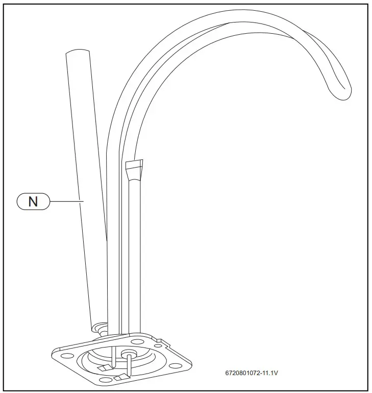
A click indicates the reset was tripped.
- Reconnect power.
IMPORTANT: Check the operation of the thermostat: - Turn temperature dial from high to low.
If the red light does not go off on low setting: - Turn off power supply and call a service person to replace the thermostat.
If the red light does go off the thermostat is working well: - Place dial setting to desired setting.
A lower setting is more economical and reduces the risk of scalding.
- Re place cover plate.
CAUTION:
Call a technician if the high limit needs to be reset frequently.
Bosch interior component diagram
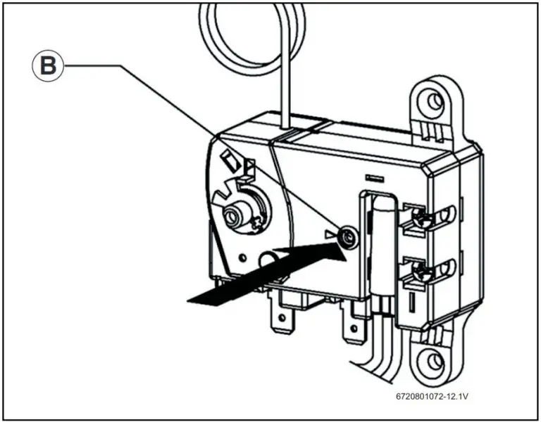
| Part | Description | TTNR | Model |
| 1 | HEATING ELEMENT 1440W | 8 738 704 439 0 | ES 2.5 / ES 4 |
| HEATING ELEMENT 1440W | 8 738 704 440 0 | ES 8 | |
| 3 | WIRED THERMOSTAT | 8 738 711 260 0 | ES 2.5 / ES 4 |
| WIRED THERMOSTAT | 8 738 711 261 0 | ES 8 | |
| 7 | HEATER WALL HANGING BRACKET | 8 738 704 443 0 | ES 2.5 / ES 4 / ES 8 |
| 14 | PLASTIC COVER | 8 738 704 446 0 | ES 2.5 / ES 4 / ES 8 |
| 18 | KNOB | 8 738 704 444 0 | ES 2.5 / ES 4 / ES 8 |
| 22 | VALVE T&P ¾ | 8 738 704 445 0 | ES 2.5 / ES 4 / ES 8 |
| 23 | MAGNESIUM ANODE D:14 L:155 M4 | 8 738 704 447 0 | ES 2.5 / ES 4 |
| MAGNESIUM ANODE D:16 L:195 | 8 738 704 448 0 | ES 8 | |
| 31 | LOCK NUT M6 | 8 738 704 449 0 | ES 2.5 / ES 4 / ES 8 |
| 33 | GASKET WITH 4 BOLTS | 8 738 704 450 0 | ES 2.5 / ES 4 / ES 8 |
| 38 | SIGNAL LAMP CAP | 8 738 704 451 0 | ES 2.5 / ES 4 / ES 8 |
| 44 | CABLE CLAMP | 8 738 704 452 0 | ES 2.5 / ES 4 / ES 8 |
| 50 | POWER CABLE | 8 738 704 453 0 | ES 2.5 / ES 4 |
| 70 | LEVER THERMOSTAT | 8 738 704 454 0 | ES 2.5 / ES 4 / ES 8 |
Bosch Tronic 3000T LIMITED WARRANTY
MODELS COVERED
This limited warranty is provided by Bosch Thermotechnology Corp. (“BTC”) and covers Bosch Tronic 3000T heaters Models ES2.5, ES4 and ES8 (hereinafter referred to as “Water Heater”). This warranty is provided to the original purchaser of the Water Heater as long as the Water Heater remains installed at its original place of installation.
WARRANTY COVERAGE
Limited Warranty
Water Heater Inner Tank (“Inner Tank”) – BTC warrants that the Inner Tank shall remain free of leaks for six (6) years from the date of installation or from date of manufacture if proof of installation is not available, provided it is properly installed and maintained and the other conditions of this warranty are met. If BTC determines that the Product has a defect in workmanship or materials, BTC, at its option, will repair or replace the defective part.
OTHER WATER HEATER COMPONENTS (“Other Components”)
BTC warrants that Other Components will remain free from defects in workmanship and materials for two (2) years from date of original installation or from date of manufacture if proof of installation is not available.
ITEMS NOT COVERED
This limited warranty does not cover the following circumstances:
- Components or parts not provided by BTC.
- Scratches in or discoloration of finishes.
- Serviceable items and normal maintenance as required per the Installation and Maintenance Manual.
- The workmanship of any installer. BTC disclaims and does not assume any liability of any nature for unsatisfactory performance caused by improper installation, repair or maintenance.
- Any labor or material costs for removal, reinstallation, repair and replacement of the defective component or part.
- Electricity or fuel costs, or any increases or unrealized savings in same, for any reason whatsoever.
- Damage caused by abuse, accident, neglect, excessive temperatures or pressures, electrochemical reaction, water and air impurities, electrical failures, flooding or acts of God.
- Damage caused by lack of maintenance of anode rod. See Installation Manual for details.
- Shipping charges, delivery expenses or administrative fees incurred by the purchaser in repairing or replacing the Water Heater.
CONDITIONS OF WARRANTY
The warranty herein is void under the following circumstances:
- Failure or malfunction resulting from improper or negligent operation, accident, abuse, freezing, electrical imbalance characteristics, misuse, unauthorized alteration, incorrect electrical supply, electrical surges, or improper installation, repair or maintenance. See the Installation Manual for installation and maintenance information.
- Failure or malfunction resulting from contaminated or corrosive air or liquid supply, the addition of unapproved chemicals, operation at abnormal temperatures, pressures or flow rates, or any attachment, accessory or component not authorized and approved by BTC. See the Installation Manual for installation and maintenance information.
- Failure or malfunction resulting from operation of Water Heater not supplied with potable water or is operated with water that may cause deposits or corrosion.
- Work performed without prior authorization or approval and without authorization/requisition number and without proper documentation verifying compliance with above terms.
LIMITED WARRANTY
OTHER THAN THE OBLIGATIONS OF BTC EXPRESSLY SET FORTH HERIN, BTC DISCLAIMS ALL WARRANTIES, EXPRESS OR IMPLIED, INCLUDING BUT NOT LIMITED TO ANY IMPLIED WARRANTIES OF MERCHANTABILITY OR FITNESS FOR A PARTICULAR PURPOSE. BTC’S SOLE OBLIGATION WITH RESPECT TO THE PRODUCT AND PURCHASER’S EXCLUSIVE REMEDIES ARE SET FORTH IN THE FOREGOING LIMITED WARRANTY. BTC SHALL NOT BE LIABLE FOR ANY INDIRECT, PUNITIVE, INCIDENTAL, SPECIAL, CONSEQUENTIAL OR SIMILAR DAMAGES INCLUDING, WITHOUT LIMIITATION, INJURY OR DAMAGE TO PERSONS OR PROPERTY OR DAMAGES FOR LOSS OF USE, LOST PROFITS, INCONVENIENCE OR LOSS OF TIME.NOTE THAT ANY REPAIRED OR REPLACED PRODUCT WILL BE WARRANTED FOR ONLY THE UNEXPIRED TERM OF THE ORIGINAL WARRANTY.
Some states do not allow the exclusion of limitation of damages, or limitations on how long an implied warranty lasts, so the above limitations and exclusions may not apply to you.
WARRANTY CLAIMS PROCESS
If you have a warranty claim you should notify the dealer who sold the Water Heater or submit the warranty claim directly to BTC at Bosch Thermotechnology Corp., 50 Wentworth Avenue, Londonderry, NH 03053. To process your claim, you will need a copy of your original invoice or other proof of purchase and documentation showing the Water Heater Model number,
Serial Number, original installation date, place of purchase, and installer’s name. The alleged defective components or parts must be returned to BTC in accordance with BTC procedure then in force for handling goods returned for the purpose of inspection to determine cause of failure (contact BTC if you
have questions regarding the return process). If BTC determines that the returned components and/or parts are defective and that this warranty applies, BTC will furnish the repaired or replacement components and/ or parts to an authorized BTC distributor who, in turn, will forward the components and/or parts to the heating contractor who installed your Water Heater.This Warranty applies to Product installed in the Continental United States and Canada only