BOSCH Universal Oxygen Sensor Installation Guide
Bosch Universal Oxygen Sensor Installation Instructions
Please read these instructions carefully before removing the installed oxygen sensor from your vehicle
Tools required to perform installation:
Oxygen sensor removal tool or 22mm wrench
Wire cutter
Wire stripper
Tape measure
Contents of Bosch Universal Oxygen Sensor Connector Kit:
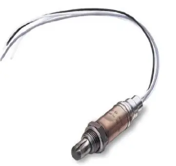
Bosch Universal Oxygen Sensor (Qty. 1)
Connector Body (Qty. 1)
Connector Cap (Qty. 1)
Posi-Lock* connectors (Qty. 4) *(Posi-Lock is a registered trademark of Swenco Co.)
Wire seals (Qty. 8)
Important Installation Notes (Please read these notes before the installation):
Before removing the original equipment oxygen sensor (hereinafter OE Sensor) from your vehicle, make note of the location of the connectors joining the oxygen sensor and vehicle wiring. The vehicle manufacturer has deemed this to be a suitable environment for a connection and it is recommended that the universal connector be installed close to the OE Sensor connection point if possible. Also note the
routing of the OE Sensor to ensure the Bosch Universal Oxygen Sensor is routed the same way.
Do not cut the wiring while removing the OE Sensor from the vehicle, as it is necessary to utilize a portion of this wiring on the Bosch Universal Oxygen Sensor.
Installation Steps:
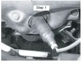
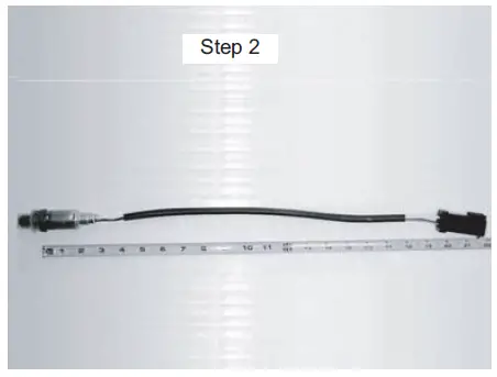
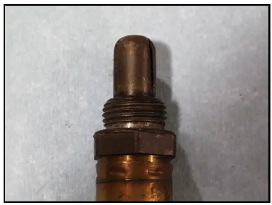
Remove the OE Sensor from vehicle. This is a sample installation location. Oxygen sensors can be located in a manifold or exhaust pipe.

If there are special clips or grommets attached to the OE Sensor, proceed to Step 3. Otherwise, if the length from the hex/flange face to end of OE Sensor connector housing
is less than 29 1/2″, proceed to Step 4, otherwise, proceed to Step 5.
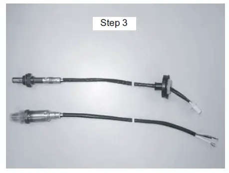
Cut the OE Sensor harness so as to include special clips or grommets. Lay the Bosch Universal Oxygen Sensor beside the OE Sensor and cut the Bosch Universal Oxygen Sensor wiring to the length of the OE Sensor,
but do not cut to less than 5″ (hex/flange face to end of sensor wire). Proceed to Step 6.
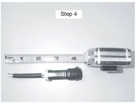
Cut the wiring of OE Sensor 4″ from end of connector as illustrated. Lay the Bosch Universal Oxygen Sensor beside the OE Sensor and cut the Bosch Universal Oxygen
Sensor wiring to the length of the OE Sensor. Proceed to Step 6.
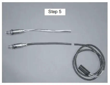
Lay the OE Sensor beside the Bosch Universal Oxygen Sensor and cut the OE Sensor wires to the same length as the Bosch Universal Oxygen Sensor length. Cut the wire
tie from the end of the Bosch Universal Oxygen Sensor wiring. Proceed to Step 6.
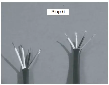
Strip 3/8″ of wire insulation from all wire ends. Use proper tools to ensure stripping only the insulation.
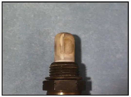
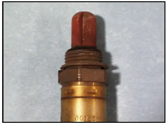
Oxygen Sensor Faces
External Oil Contamination
Fuel Contamination
Coolant Contamination
Oil Contamination
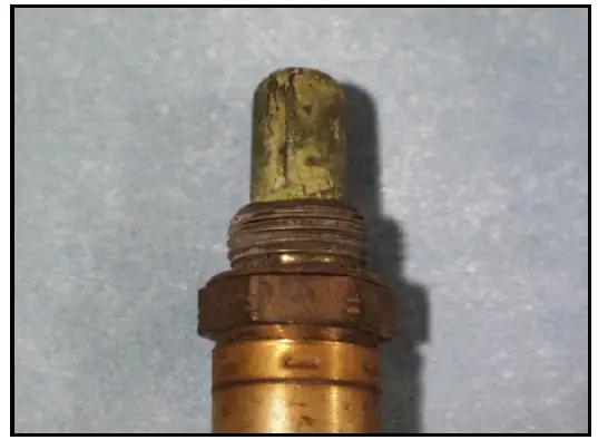
Fuel Contamination
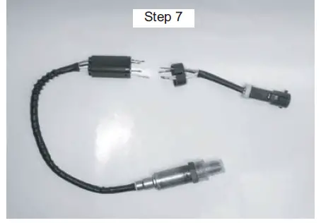
Utilizing “Wire Color Reference Table”, match the wires of the OE Sensor connector (column A) to the wires of Bosch Universal Oxygen Sensor (column B). Install the Connector Cap over the wires of the OE Sensor connector. Install the Connector Body over the wires of the Bosch Universal Oxygen Sensor.
Install a wire seal over each wire so that the unribbed end of the seal is facing the Connector Body and Cap. Check that the wires are aligned properly before proceeding.
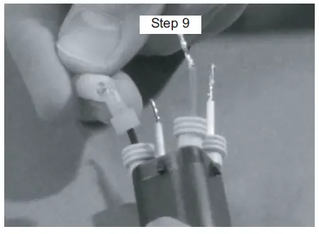
Insert a wire of the Bosch Universal Oxygen Sensor into the male end of the Posi-Lock connector. Keeping slight pressure on the wire, hand tighten the male end into the Posi- Lock barrel. Repeat for the remaining wires of the Bosch Universal Oxygen Sensor, and insert wires of the OE Sensor connector into the male ends of the Posi-Lock connectors.
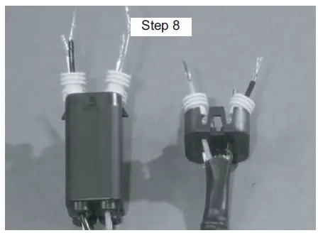
Utilizing “Wire Color Reference Table”, begin connecting the wires of the OE Sensor connector harness as described in Step 7. Be sure to avoid criss-crossing the wires. Grasp the wire on each side of the Posi-Lock
connector and pull firmly to insure proper assembly.
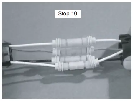
Push the wire seals against the Posi-Lock connector. Insert the Posi-Lock and wire seals into the Connector Body. Push the Connector Cap down onto the Connector Body until both
tabs lock into position.
Remove the protective cap from the Bosch Universal Oxygen Sensor and re-install onto vehicle. It is critical to locate wires away fromb sources of extreme heat and possible
abrasion, utilizing any clips or grommets from the OE Sensor wire harness.
Wire Color Reference Table:
|
OE Sensor Types |
Signal Wire | Heater Wires* (2 wires) | Ground Wire (optional) | |||
|
OE Sensor (A)** |
Bosch Universal Oxygen Sensor (B)** |
OE Sensor (A)** |
Bosch Universal Oxygen Sensor (B)** |
OE Sensor (A)** |
Bosch Universal Oxygen Sensor (B)** | |
| Bosch | Black |
Black |
White |
White |
Gray |
Gray |
| Type A | Purple | Dark Brown | Light Brown | |||
| Type B | Blue | Black | White | |||
| Type C | White | Black | Green | |||
| Type D | Black | White | Gray | |||
| 1996-95 Mazda Millenia (V6-2.5L)
1996-95 Ford Probe, Mazda 626 (V6) |
Black | White | Red | |||
| 1995-91 Geo Tracker, Suzuki
Sidekick |
Black | Red | No Ground | |||
* Since there is no polarity to the heaters, it is only important to match the color of the heater wires.
** Wire color(s) of column (A) in each wire type should match wire color(s) of column (B).