Bushnell® 201360/201361 Tour V3 Slope Laser Rangefinder User Guide
Literature #: 98-2389/06-13
CONGRATULATIONS ON YOUR PURCHASE OF THE BUSHNELL® TOUR V3™
INCORPORATING PINSEEKER™ TECHNOLOGY WITH JOLT™. The TOUR V3 is a precision Laser Rangefinding optical instrument designed to provide many years of enjoyment. This booklet will help you achieve optimum performance by explaining its adjustments and features as well as how to care for this precise laser rangefinding optical instrument. To ensure optimal performance and longevity, please read these instructions before using your TOUR V3.
INTRODUCTION
Your Tour V3 is Bushnell’s newest addition to an award winning line of golf laser rangefinders specifically made for golfers. Tour V3 features PinSeeker™ technology with JOLT™, allowing the golfer to easily and quickly “zero” in on the flag without acquiring background targets. The Tour V3 weighs a mere 6.6 ounces and made to fit into the palm of your hand. Tour V3 also features an adjustable eyepiece, 5X magnification, and is capable of providing distance from 5 to 1000 yards with incredible one yard accuracy! Like other Bushnell laser rangefinders, the Tour V3 is not dependent upon reflectors, and will provide distance to trees, bunkers, and virtually any object on any golf course in the world.
HOW OUR DIGITAL TECHNOLOGY WORKS
The TOUR V3 WITH PINSEEKER emits invisible, eye safe, infrared energy pulses. The TOUR V3’s Advanced Digital microprocessor and ASIC chip (Application-Specific Integrated Circuit) results in instantaneous and accurate readings every time. Sophisticated digital technology instantaneously calculates distances by measuring the time it takes for each pulse to travel from the rangefinder, to the target, and back.
RANGING ACCURACY
The ranging accuracy of the TOUR V3 is plus or minus one yard/meter under most circumstances. The maximum range of the instrument depends on the reflectivity of the target. The maximum distance for most objects is 700 yards/640 meters while for highly reflective objects the maximum is 1000 yards/914 meters. Note: You will get both longer and shorter maximum distances depending on the reflective properties of the particular target and the environmental conditions at the time the distance of an object is being measured.
The color, surface finish, size and shape of the target all affect reflectivity and range. The brighter the color, the longer the range. Red is highly reflective, for example, and allows longer ranges than the color black, which is the least reflective color. A shiny finish provides more range than a dull one. A small target is more difficult to range than a larger target. The angle to the target also has an effect. Shooting to a target at a 90 degree angle (where the target surface is perpendicular to the flight path of the emitted energy pulses) provides good range while a steep angle on the other hand, provides limited ranging. In addition, lighting conditions (e.g. the amount of sunlight) will affect the ranging capabilities of the unit. The less light (e.g. overcast skies) the farther the unit’s maximum range will be. Conversely, very sunny days will decrease the unit’s maximum range.
GETTING STARTED
INSERTING THE BATTERY
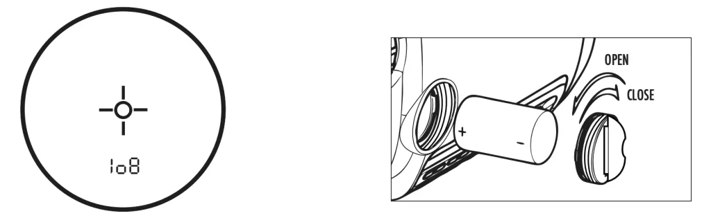
Remove the battery cap by lifting the battery cap tab and then rotating counter clockwise. Insert a CR-2 3-volt lithium battery into the compartment positive end first, then replace the battery cap.
NOTE: It is recommended that the battery be replaced at least once every 12 months.
Low Battery Indicator: If “ “ is displayed within the in-view readout, this means “low battery” or battery charge is getting low and the 3-volt lithium battery should be replaced.
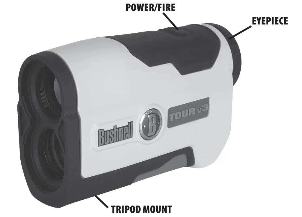
ADJUSTING THE EYEPIECE
Your TOUR V3 is constructed with an adjustable eyepiece (+/- 2 Diopter Adjustment) that allows one to focus the LCD display relative to the image. Simply rotate the eyepiece until the reticle and object distanced to are both in focus to your eye.
OPERATIONAL SUMMARY
While looking through the 5x eyepiece, depress the POWER/FIRE button once to activate the in-view Liquid Crystal Display (LCD). Place the aiming circle (located in the center of the field of view) upon a target at least 5 yards away, depress and hold the POWER/FIRE button down until the range reading is displayed near the bottom of the in-view display. Crosshairs surrounding the aiming circle indicate that the laser is being transmitted. Once a range has been acquired, you can release the POWER/FIRE button. The crosshairs surrounding the aiming circle will disappear once the POWER/FIRE button has been released (i.e. the laser is no longer being transmitted). Note: Once activated, the LCD will remain active and display the last distance measurement for 30 seconds. You can depress the power button again at any time to distance to a new target. As with any laser device, it is not recommended to directly view the emissions for long periods of time with magnified lenses. The maximum time the laser is transmitted (fired) is 10 seconds. To re-fire, press the POWER/FIRE button down again.
LIQUID CRYSTAL DISPLAY (LCD) INDICATORS
Your TOUR V3 ’s LCD incorporates illuminated icons or symbols that indicate the selected unit of measure, when the laser is actively firing, when a target has been acquired, and targeting modes. A summary of these features follows:
MODE and UNIT OF MEASURE OPTIONS
The TOUR V3 can be used to measure distances in yards or meters. The unit of measure indicators are located in the lower right portion of the LCD. To select between yards and meters, press and hold the POWER/FIRE button. The display will begin to cycle through the setup options: Yards w/JOLT, Yards, Meters w/JOLT, Meters (for details on the JOLT feature, see “About JOLT”). When the units and JOLT mode you want to use are displayed, release the POWER/FIRE button to select it. If you are changing from yards to meters, a change in unit of measure will be indicated by the illumination of the M for meter indicator while the Y for Yard indicator is turned off. If you are changing from meters to yards, the opposite will occur. The TOUR V3 will return to the last unit of measure setting used each time the unit is turned on.
ACTIVE LASER
Crosshairs surrounding the aiming circle indicate that the laser is being transmitted. Once a range has been acquired, you can release the POWER/FIRE button. The crosshairs surrounding the circle will disappear once the POWER/FIRE button has been released (i.e. the laser is no longer being transmitted).
PinSeeker (LCD Indicator –  ) Ever have trouble getting distance to the flag? This advanced mode allows easy acquisition of the flag without inadvertently getting distances to background targets (i.e. trees) that have stronger signal strength.
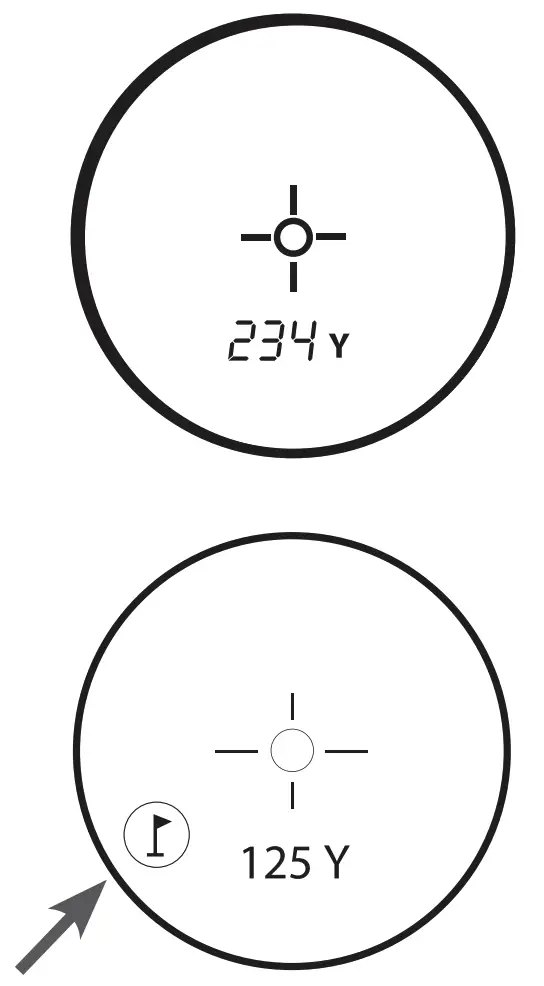 Press the POWER/FIRE button to turn the unit on. Next, align the aiming circle reticle onto the flag that you want distance to. Then, press and hold the POWER/ FIRE button and move the laser slowly over the flag or desired object until a circle surrounds the flag indicator. If the laser beam recognized more than one object (i.e. flag and background trees), distance of the flag will be displayed and a circle will surround the PinSeeker indicator informing the user that distance to the flag (i.e. closer object) is being displayed in the LCD (as seen below). There may be times when only the laser beam only sees one object in its path. In this case, the distance will be displayed, but because more than one object was not acquired, a circle will not surround the flag indicator.
TIP: While pressing the POWER/FIRE button, you can move the device slowly from object to object and intentionally force the laser to hit multiple objects to ensure that you are only displaying the closest of the objects recognized by the laser.
Once the device has shut off, the unit will always default back to the last mode used.
About JOLT
The new JOLT feature allows you to enable (at your option-see “Unit of Measure Options”) a vibration signal (similar to setting a cell phone to “vibrate”) that will be felt when the Pinseeker technology indicates the flag has been detected and the distance to it is displayed in the LCD.
Tour V3 – Slope Edition (LCD Indicator –  ) This advanced and patented technology found on SLOPE EDITION models features a built-in accelerometer-based inclinometer that digitally displays the exact slope angle from -20 to +20 degrees of elevation and is +/- 1.0 degree accurate. The Slope +/-™ Edition models will automatically compute an angle compensated range based upon distance and slope angle determined by the laser rangefinder and built-in inclinometer. This data is then combined with internal algorithmic formulas dealing with average club use and ball trajectories. The angle compensated range provides direction on how to play the shot (i.e. add distance if an incline, subtract distance if a decline).
How Slope™ Works
 Press the POWER/FIRE button to obtain distance to the flag or other objects. Once the range is acquired, release the POWER/FIRE button. Once you have released the power button, a degree of angle and compensated range will be displayed beneath the standard distance as seen below.
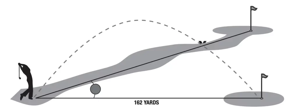
n the example on the right, the true distance is 162 yards, slope is +4 degrees, and the compensated range is 173 yards. The “ ” symbol means “Play-As”, so instead of playing as 162 yards, “play-as” 173 yards.
The Advantage of Slope Edition
The distance to flag A in the drawing below is 162 yards. It is also 162 yards to flag B although it is on a slope. However, if you were to play this hole as 162 yards, the ball (X) would fall short of the hole/flag because you did not take slope into account.
OPTICAL DESIGN
Magnification and Coatings
The TOUR V3 features 5x magnification and Multi-Coated optics. A liquid crystal display (LCD) is mounted within the optical system and when activated, displays a reticle for targeting, yards/meters, and Mode indicators. Inherent in the manufacturing process are small black spots that appear in the optical system. These are a natural characteristic of the LCD and cannot be fully eliminated in the manufacturing process. They do not affect the distancing performance of the unit.
TRIPOD MOUNT
Molded into the bottom of your TOUR V3 is a threaded tripod mount that will allow you to attach to the following Bushnell Golf Accessories:
Golf Cart Mount: Attaches the rangefinder to your golf cart for easy access. Quick release clamp attaches to a golf cart and can be easily removed afterwards.
Push/Pull Cart Monopod: Steady your hand with this telescoping monopod. Simply attach rangefinder to the monopod and insert into cart umbrella holder.
SPECIFICATIONS:
Dimensions: Measuring 4.3 x 2.8 x 1.6 inches
Weight: 6.6 oz.
Ranging Accuracy: +/- 1 yard
Range: 5-1000 Yards / 5-914 Meters
Magnification: 5x
Objective Diameter: 24 mm
Optical Coatings: Multi-Coated
Display: LCD
Power Source: 3-volt lithium (included)
Field Of View: 367 ft. @ 1000 yards
Extra Long Eye Relief: 21mm
Exit Pupil: 4.8 mm
Built-In Tripod Mount
Includes battery & carrying case
Patent #’s: 6,445,444 | 5,612,779 | 6,057,910 | 6,226,077 (Slope Edition) | 7,239,377 | 7,859,650 | 7,535,553
CLEANING
Gently blow away any dust or debris on the lenses (or use a soft lens brush). To remove dirt or fingerprints, clean with a soft cotton or microfiber cloth, rubbing in a circular motion. Use of a coarse cloth or unnecessary rubbing may scratch the lens surface and eventually cause permanent damage. For a more thorough cleaning, photographic lens tissue and photographic-type lens cleaning fluid or isopropyl alcohol may be used. Always apply the fluid to the cleaning cloth – never directly on the lens.
TROUBLESHOOTING
If unit does not turn on – LCD does not illuminate:
- Depress POWER/FIRE button.
- Check and if necessary, replace battery.
If unit does not respond to key presses, replace the battery with a good quality 3 volt lithium battery.
If unit powers down (display goes blank when attempting to power the laser):
- The battery is either weak or low quality. Replace the battery with a good quality 3 -volt lithium battery.
If target range cannot be obtained:
- Make sure LCD is illuminated.
- Make sure that the POWER/FIRE button is being depressed.
- Make sure that nothing, such as your hand or finger, is blocking the objective lenses (lenses closest to the target) that emit and receive the laser pulses.
- Make sure unit is held steady while depressing the POWER/FIRE button.
NOTE: The last range reading does not need to be cleared before ranging another target. Simply aim at the new target using the LCD’s reticle, depress the POWER/FIRE button and hold until new range reading is displayed.
Specifications, instructions, and the operation of these products are subject to change without notice.
FCC NOTE
This equipment has been tested and found to comply with the limits for a Class B digital device, pursuant to Part 15 of the FCC Rules. These limits are designed to provide reasonable protection against harmful interference in a residential installation. This equipment generates, uses and can radiate radio frequency energy and, if not installed and used in accordance with the instructions, may cause harmful interference to radio communications. However, there is no guarantee that interference will not occur in a particular installation. If this equipment does cause harmful interference to radio or television reception, which can be determined by turning the equipment off and on, the user is encouraged to try to correct the interference by one or more of the following measures:
- Reorient or relocate the receiving antenna.
- Increase the separation between the equipment and receiver.
- Connect the equipment into an outlet on a circuit different from that to which the receiver is connected.
- Consult the dealer or an experienced radio/TV technician for help.
Shielded interface cable must be used with the equipment in order to comply with the limits for a digital device pursuant to Subpart B of Part 15 of FCC Rules.
Specifications and designs are subject to change without any notice or obligation on the part of the manufacturer.
FDA SAFETY
Class 1 laser product in accordance with IEC 60825-1:2007.
Complies with 21 CFR 1040.10 and 1040.11 for laser products except for deviations pursuant to Laser Notice No. 50, dated June 24, 2007.
Caution: There are no user controls, adjustments or procedures. Performance of procedures other than those specified herein may result in access to invisible laser light.

![]()
www.bushnellgolf.com
9200 Cody, Overland Park, KS 66214
4 rue Diderot, Suresnes, France 92150
©2012 Bushnell Outdoor Products
Bushnell,™, ®, denotes trademark of Bushnell Outdoor Products
Literature #: 98-2389/06-13