
CNDY Shield GRBL CNC Arduino UNO User Guide
V1.2
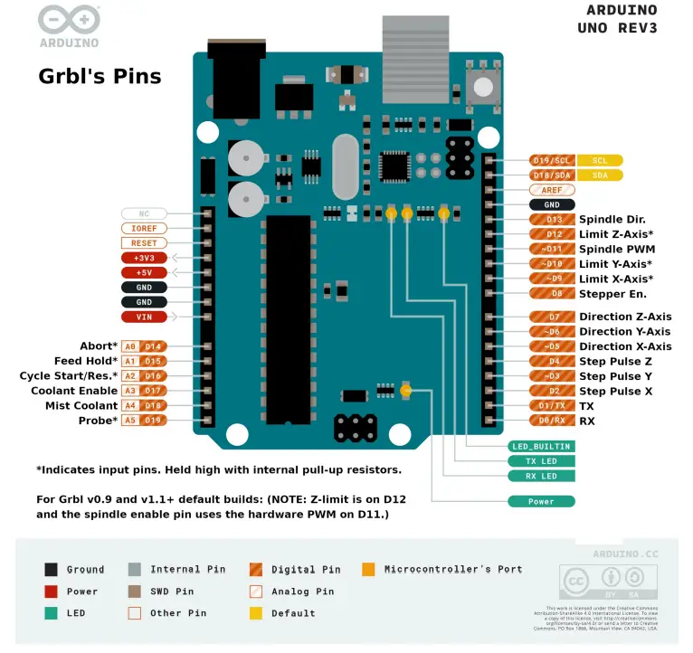
GRBL pinout on the Arduino Uno
Analog 0 = Abort Button*
Analog 1 = Feed Hold Button* (SAFETY_DOOR is shared with feed hold. Enabled by config define)
Analog 2 = Cycle Start / Restart Button*
Analog 3 = Coolant Enable Output
Analog 4 = (Optional) Mist Coolant Output (or ALARM_STATE diagnostic light**)
Analog 5 = Probe Input*
Digital 13 = Spindle Direction
Digital 12 = Limit Switches Z-Axis*
Digital 11 = Spindle / Laser Enable PWM
Digital 10 = Limit Switches Y-Axis*
Digital 9 = Limit Switches X-Axis*
Digital 8 = Stepper Motors Enable / Disable
Digital 7 = Direction Z-Axis
Digital 6 = Direction Y-Axis
Digital 5 = Direction X-Axis
Digital 4 = Step Pulse Z-Axis
Digital 3 = Step Pulse Y-Axis
Digital 2 = Step Pulse X-Axis
Optional dual axis feature
Uno Analog Pin 3 = A-axis DUAL_DIRECTION (used to be Coolant Enable Output)
Uno Analog Pin 4 = A-axis DUAL_STEP (used to be Optional Mist Coolant Output)
Uno Digital 13 = Coolant (replacing spindle direction.)
After installing the grbl repository as a library in Arduino, uncomment out the following lines in config.h file in the grbl library folder.
#define ENABLE_DUAL_AXIS // Default disabled. Uncomment to enable.
// Select the one axis to mirror another motor. Only X and Y axis is supported at this time.
#define DUAL_AXIS_SELECT Y_AXIS // Must be either X_AXIS or Y_AXIS
NOTE: Dual axis limit is shared with the (Z-Axis) limit pin by default.
Dual axis feature requires an independent step pulse pin to operate. The independent direction pin is not absolutely necessary but facilitates easy direction inverting with a Grbl $$ setting. These pins replace the spindle direction and optional coolant mist pins.
This optional dual axis feature is primarily for the homing cycle to locate two sides of a dual-motor gantry independently, i.e. self-squaring. This requires an additional limit switch for the cloned motor. To self square, both limit switches on the cloned axis must be physically positioned to trigger when the gantry is square. Highly recommend keeping the motors always enabled to ensure the gantry stays square with the $1=255 setting.
For Grbl on the Arduino Uno, the cloned axis limit switch must to be shared with and wired with z-axis limit pin due to the lack of available pins. The homing cycle must home the z-axis and cloned axis in different cycles, which is already the default config.
The dual axis feature works by cloning an axis step output onto another pair of step and direction pins. The step pulse and direction of the cloned motor can be set independently of the main axis motor. However to save precious flash and memory, this dual axis feature must share the same settings (step/mm, max speed, acceleration) as the parent motor. This is NOT a feature for an independent fourth axis. Only a motor clone.
WARNING: Make sure to test the directions of your dual axis motors! They must be setup to move the same direction BEFORE running your first homing cycle or any long motion! Motors moving in opposite directions can cause serious damage to your machine! Use this dual axis feature at your own risk.
NOTE: This feature requires approximately 400 bytes of flash. Certain configurations can run out of flash to fit on an Arduino 328p/Uno. Only X and Y axes are supported. Variable spindle/laser mode IS supported, but only for one config option. Core XY, spindle direction pin, and M7 mist coolant are disabled/not supported.
To prevent the homing cycle from racking the dual axis, when one limit triggers before the other due to switch failure or noise, the homing cycle will automatically abort if the second motor’s limit switch does not trigger within the three distance parameters defined below. Axis length percent will automatically compute a fail distance as a percentage of the max travel of the other non-dual axis, i.e. if dual axis select is X_AXIS at 5.0%, then the fail distance will be computed as 5.0% of y-axis max travel. Fail distance max and min are the limits of how far or little a valid fail distance is.
#define DUAL_AXIS_HOMING_FAIL_AXIS_LENGTH_PERCENT 5.0 // Float (percent)
#define DUAL_AXIS_HOMING_FAIL_DISTANCE_MAX 25.0 // Float (mm)
#define DUAL_AXIS_HOMING_FAIL_DISTANCE_MIN 2.5 // Float (mm)
Note for I2C Port
Analog 4 (A4) and Analog 5 (A5) are used for the I2C port on the Arduino Uno or 328p. This means that as long as you are using the default probe function, mist coolant, dual-axis, or custom ALARM_STATE LED diagnostic light, using I2C will not be possible. Communication with another Arduino to increase functionality will have to be over the serial connection on D0 and D1.
Getting Started (Stepper Drivers)
First, to connect your stepper motors to Grbl, you’ll need some stepper motor drivers to power the steppers and connect your driver inputs to the Arduino controller pins. There are a number of drivers that can do this, available as fully pre-built, partially pre-built, or completely DIY. The stepper drivers will need to share the stepper enable pin (D8) to their respective enable pins, while the direction and step pulse pins (D2-D7) will need to be connected to their respective pins on the drivers. Just make sure that all of your drivers and the Arduino share a common ground (star grounded with your motor driver power). This is about all you’ll need to get started.
Homing and Limit Switches
Afterwards, once you decide that you’re ready or would like to enable homing and/or hard limits, you’ll need to connect a normally-open limit switch to each of the limit pins (D9, D10, and D12). Homing and hard limits use the same switches. These limit pins are already held high with an internal pull-up resistor, so all you have to do is wire them to ground. So when you close a switch, the switch will pull the limit pin to ground. If you’d like to have hard limit switches on both ends of travel of an axis, just wire two limit switches in parallel to the axis limit pin and ground. Make sure you have the switches installed before attempting to perform a homing cycle, and make sure you practice good wiring methods to minimize external electric noise on the input pins.
Good wiring practices might include using shielded cables or clamp-on ferrite cable cores, and using some 0.1uF capacitors in parallel with the limit switches for debouncing / noise filtering. Keeping the motor wires away from the limit switch wires may also be a good idea.
It is possible to configure GRBL to use normally-closed limit switches if you so desire. Some feel that normally closed limit switches may help to reduce a catastrophic crash in the event of a limit switch failure. Many users omit using any limit switches at all and instead opt for software limits instead.
Control Buttons
In Grbl v0.8 and later, there are pin-outs of the cycle start, feed hold, and reset runtime commands, so you can have physical control buttons on your machine. Just like the limit pins, these pins are held high with an internal pull-up resistor, so all you have to do is connect a normally-open switch to each pin and to ground. Again make sure you practice good wiring methods to minimize external electric noise on the input pins.
Spindle and Coolant Pins
If you have a desire or need for spindle (D13) or coolant control (A3 & A4) , Grbl will toggle these output pins high or low, depending on the G-code commands you send to Grbl. With v0.9+ and variable spindle PWM enabled, the D11 pin will output a range of voltages from 0V to 5V depending the spindle speed G-code command. 0V indicates spindle off in this case. Since these pins are all application dependent in how they are used, we’ll leave it to you to determine how to control and use these for your machine. You can also hack the spindle and coolant control source files to easily alter how they work and then compile and upload your modified Grbl through the Arduino IDE.
Diagnostic LED light
Commercial CNC machines often have at least one diagnostic LED beacon in the event of a machine crash or alarm code. For those new to GRBL and DIY CNC machines, this feature is very useful to know when an ALARM_STATE has occurred (such as failing to home the machine with homing and limit switches enabled).
GRBL by default does not have a diagnostic LED light. This is because the Ardunio UNO with the 328p chip has limited programming space and nearly all that space is currently being used (though not all!). Not every desirable feature can be implemented on such a low memory device so sometimes sacrifices have to be made.
Additionally all the available I/O ports are currently being used and at least one I/O pin is needed for such a light. Fortunately this functionality can be easily added by hacking the GRBL C code and there is still about 3% memory available on the 328p chip!
Many machines do not currently use the optional MIST COOLANT feature on Analog 4, so we can easily redefine this pin for our use. An alternate method might be to code such LED lights on an external Arduino which would then have all the I/O ports available where one could wire up as many LED lights / Buzzers as wanted and could communicate over Serial or I2C.
To hack the GRBL source code to use the ALARM LED on the CNDY Shield please do the following:
Step 1: On Linux or Macintosh open up a text editor (on Windows use Notepad++) and edit the cpu_map.h file:
Change this:
// Define flood and mist coolant enable output pins.
#define COOLANT_FLOOD_DDR DDRC
#define COOLANT_FLOOD_PORT PORTC
#define COOLANT_FLOOD_BIT 3 // Uno Analog Pin 3
#define COOLANT_MIST_DDR DDRC
#define COOLANT_MIST_PORT PORTC
#define COOLANT_MIST_BIT 4 // Uno Analog Pin 4
To this:
// Define flood and mist coolant enable output pins.
#define COOLANT_FLOOD_DDR DDRC
#define COOLANT_FLOOD_PORT PORTC
#define COOLANT_FLOOD_BIT 3 // Uno Analog Pin 3
//#define COOLANT_MIST_DDR DDRC
//#define COOLANT_MIST_PORT PORTC
//#define COOLANT_MIST_BIT 4 // Uno Analog Pin 4
//////////////////
// Define ALARM LED OUTPUT
#define SIGNAL_LIGHT_DDR DDRC
#define SIGNAL_LIGHT_PORT PORTC
#define SIGNAL_LIGHT_BIT 4 // Uno Analog Pin 4
// #define signal_light(on) (SIGNAL_LIGHT_DDR |= (1<<SIGNAL_LIGHT_BIT), SIGNAL_LIGHT_PORT &= (1<<SIGNAL_LIGHT_BIT), SIGNAL_LIGHT_PORT |= (1<<SIGNAL_LIGHT_BIT) )
// #define signal_light_init() signal_light(off)
#define signal_light_init signal_light_off
#define signal_light_on (SIGNAL_LIGHT_DDR |= SIGNAL_LIGHT_PORT |= (1<<SIGNAL_LIGHT_BIT) )
#define signal_light_off (SIGNAL_LIGHT_DDR |= SIGNAL_LIGHT_PORT &= ~(1<<SIGNAL_LIGHT_BIT) )
//////////////////
Step 2: On Linux or Macintosh open up a text editor (on Windows use Notepad++) and edit the protocol.c file:
Change this:
// Executes run-time commands, when required. This function primarily operates as Grbl’s state
// machine and controls the various real-time features Grbl has to offer.
// NOTE: Do not alter this unless you know exactly what you are doing! void protocol_exec_rt_system()
{
uint8_t rt_exec; // Temp variable to avoid calling volatile multiple times.
rt_exec = sys_rt_exec_alarm; // Copy volatile sys_rt_exec_alarm.
if (rt_exec) { // Enter only if any bit flag is true
// System alarm. Everything has shutdown by something that has gone severely wrong. Report
// the source of the error to the user. If critical, Grbl disables by entering an infinite
// loop until system reset/abort.
sys.state = STATE_ALARM; // Set system alarm state
report_alarm_message(rt_exec);
To this:
// Executes run-time commands, when required. This function primarily operates as Grbl’s state
// machine and controls the various real-time features Grbl has to offer.
// NOTE: Do not alter this unless you know exactly what you are doing!
void protocol_exec_rt_system()
{
uint8_t rt_exec; // Temp variable to avoid calling volatile multiple times.
rt_exec = sys_rt_exec_alarm; // Copy volatile sys_rt_exec_alarm.
///////////////////////
// Define ALARM LED OUTPUT
signal_light_init; //init LED in off state
if (sys.state==STATE_ALARM) {signal_light_on;}
else if (sys.state!=STATE_ALARM) {signal_light_off;}
// else {signal_light_off;}
///////////////////////
if (rt_exec) { // Enter only if any bit flag is true
// System alarm. Everything has shutdown by something that has gone severely wrong. Report
// the source of the error to the user. If critical, Grbl disables by entering an infinite
// loop until system reset/abort.
sys.state = STATE_ALARM; // Set system alarm state
report_alarm_message(rt_exec);
What we just did was change the defined function of Analog 4 (A4) from being the optional mist coolant to being our LED light. Then we wrote code in C to be able to write (PC4) Port C 4 (Analog4) high or low depending on whether it was told to be on or off. Then we wrote a simple if-else statement to check the GRBL state machine and tell us whether we are in an active ALARM_STATE, and when we are to turn on the LED.
If all goes well we can then compile in the Arduino IDE, upload the code, and we will now have a working ALARM_STATE LED diagnostic light! We can optionally connect an external LED Beacon Light to place high above the machine that will be visible across the room.
Possible problems
Ideally these changes will be done with the most current grbl source code available and be made BEFORE adding the grbl “library” to the Arduino IDE. If you already have grbl in your Arduino libraries folder you will need to browse manually and delete the grbl folder or edit the files within the arduino library. On my linux machine the “library” is found at: /home/andrew/Arduino/libraries/grbl. The most recent grbl release can be found at https://github.com/gnea/grbl/releases. One can download the available zip file and a folder named grbl-1.1h.20190825 can be found inside. Inside this folder a folder named grbl will be the one you will want to add to the Arduino IDE as a “library” “zip file”. Be sure to make your changes to the cpu_map.h and protocol.c files before you add it to the Arduino IDE. Otherwise you will need to edit the files within your libraries/grbl folder. There is a known bug for the dual axis feature in the grbl-1.1h zip file, it is fixed if you instead download the main grbl branch instead. https://github.com/gnea/grbl
CNDY Shield updates and errors
*V1.1: has a small silkscreen error where Spindle PWM and Spindle Direction are swapped. This has been corrected in V1.2.
V1.2 no longer has the optional noise reduction capacitors on the 5v line, and has new ones on the other input button lines. V1.2 has an optional LED wired in parallel to the Spindle PWM. This may be useful for laser setups for safety.
Updated Aug-28-2021
Additional Information can be found at RabbitMountainResearch.com.