![]()
![]() User Manual
User Manual
BEFORE YOU START
- This User Manual is intended for healthcare professionals.
- This User Manual applies to AIRVO 2 units with LOT numbers 130621 and above.
- Read this User Manual including all warnings. Failure to do so may result in injury. In addition, watch the AIRVO 2 Video Guide. Keep them both in a safe place for future reference.
- Before the AIRVO 2 is used for the first time, it must be set up according to the instructions in the AIRVO 2 Technical Manual.
- The AIRVO 2 must be cleaned and disinfected between patients according to the instructions in the
Disinfection Kit Manual (900PT600). - For further assistance, please contact your Fisher & Paykel Healthcare representative.
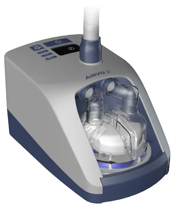
OVERVIEW
The AIRVO 2 is a humidifier with an integrated flow generator that delivers high flow warmed and humidified respiratory gases to spontaneously breathing patients through a variety of patient interfaces.
INTENDED USE
The AIRVO 2 is for the treatment of spontaneously breathing patients who would benefit from receiving high-flow warmed and humidified respiratory gases. This includes patients who have had upper airways bypassed. The flow may be from 2 – 60L/min depending on the patient interface. The AIRVO 2 is for patients in hospitals and long-term care facilities.
USA Federal Law restricts this unit for sale by or on the order of a physician.
![]()
- Nasal delivery of respiratory gases generates flow-dependent positive airway pressure (PAP). This must be taken into account where PAP could have adverse effects on a atient.
- The unit is not intended for life support.
To avoid burns: - The unit should only be used with interfaces, water chambers, and breathing tubes specified in this user manual.
- Using the breathing tube or interface for longer than the specified time can result in serious injury including infection.
- Before using oxygen with the unit, read all warnings in the “Oxygen” section of this manual.
- Never operate the unit if:
• the heated breathing tube has been damaged with holes, tears, or kinks,
• it is not working properly,
• the case screws have ever been loosened. - Do not block the flow of the air through the unit and breathing tube.
- The unit should be located in a position where ventilation around the unit is not restricted.
- Never block the air openings of the unit or place it on a soft surface such as a bed or couch/sofa, where the filter area may be blocked. Keep the air openings free of lint, hair, etc.
To avoid electric shock: - Do not store or use the unit where it can fall or be pulled into the water. If water has entered the unit enclosure, disconnect the power cord and discontinue use.
- Never operate the unit if:
• it has been dropped or damaged,
• it has a damaged power cord or plug,
• it has been dropped into water. - Avoid unnecessary removal of the power cord from the rear of the device. If removal is necessary, hold the connector during removal. Avoid pulling on the power cord.
- Return the unit to an authorized service center for examination and repair, except as outlined in this manual.
To avoid choking or inhalation of a foreign object: - Ensure an air filter is fitted when operating your unit.
- Never drop or insert any object into any opening or tube.
Miscellaneous: - Do not use the unit when the room temperature exceeds 30°C (86°F) or is below 10°C (50°F) as the unit may switch off. Humidity output will be compromised below 18°C (64°F) and above 28°C (82°F).
- The unit is not suitable for use in the presence of a flammable, anesthetic mixture with air or oxygen or nitrous oxide.
AIRVO 2 AND ACCESSORIES
Tube and chamber kits and patient interfaces
| Tube & chamber kit | Interfaces | |||
| 900PT531 | Heated breathing tube, MR290 auto-fill chamber, and adapter (10-Pack) | OPT316 OPT318 |
Nasal Cannula – Infant (20-Pack) Nasal Cannula – Pediatric (20-Pack) | |
| 900PT501 | Heated breathing tube, MR290 auto-fill chamber, and adapter (10-Pack) | OPT842 OPT844 OPT846 OPT870 RT013 |
Nasal Cannula – Small (20-Pack) Nasal Cannula – Medium (20-Pack) Nasal Cannula – Large (20-Pack) Tracheostomy Direct Connection (20-Pack) Mask Interface Adapter – 22mm (20-Pack) |
|
Cleaning and Disinfection
| 900PT600 | Disinfection Kit |
| 900PT601 | Disinfection Filter (2-Pack) |
| 900PT602 | Cleaning Sponge-Stick (20-Pack) |
| 900PT603 | Clean Storage Cover (20-Pack) |
Miscellaneous
| 900PT405 | Pole mounting tray |
| 900PT421 | Hospital stand |
| 900PT422 | Oxygen inlet extension kit |
| 900PT912 | Filter holder |
| 900PT913 | Air filter (2-Pack) |
| OPT012 | Wigglepads (OPT316/OPT318) (20-pack) |
| OPT014 | Oxygen Tubing (Optiflow Junior) |
SETTING UP ARVO 2
BEFORE YOU BEGIN
The AIRVO 2 should be fixed on a pole mounting tray (900PT405) below the patient head height.
Open the packaging of the tube & chamber kit (heated breathing tube, MR290 auto-fill chamber, and adapter).
INSTALL WATER CHAMBER
Remove the blue port caps from the chamber by pulling the tear tab upwards then remove the bracket holding the water supply tube.
Fit the supplied adapter over the two vertical ports on the chamber and push on fully then clip the water supply tube into position.
Fit the water chamber to the unit by pressing down the finger guard and sliding the chamber on, carefully aligning with the blue chamber portends.
Push the chamber on firmly until the finger guard clicks into place.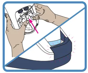
![]()
To avoid burns:
- Do not start the unit without the water chamber in place.
- The water in the chamber becomes hot during use. Exercise caution when removing and emptying the chamber.
- Do not touch the heater plate, water chamber, or chamber base during use.
To avoid electric shock: - When handling the unit with the water chamber in place, avoid tilting the machine to prevent any chance of water entering the unit enclosure.
- Empty all the water from the water chamber before transporting the unit.

To ensure optimal therapy (MR290 only): - Do not use the auto-fill MR290 chamber if it has been dropped or been run dry
and the “water out” alarm has been activated.
CONNECT WATER BAG
Attach the sterile water bag to the hanging bracket 20cm (8”) above the unit, and push the bag spike into the fitting at the bottom of the bag.
Open the vent cap on the side of the bag spike. The chamber will now automatically fill to the required level and maintain that level until the water bag is empty.
To ensure continual humidification, always ensure that the water chamber and/or water bag are not allowed to run out of water.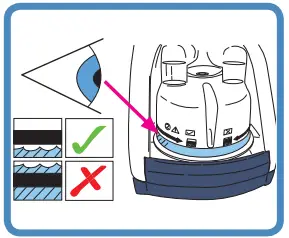
Check that water flows into the chamber and is maintained below the fill line. If the water level rises above the fill line, replace the chamber immediately.
MR290: Flow setting vs usage time (2-liter sterile water bag)
| L/min | 2 | 5 | 10 | 15 | 20 | 25 | 30 | 35 | 40 | 45 | 50 | 55 | 60 |
| hrs | 379 | 152 | 76 | 51 | 38 | 30 | 25 | 22 | 19 | 17 | 15 | 14 | 13 |
INSTALL HEATED BREATHING TUBE
One end of the heated breathing tube has a blue plastic sleeve. Lift the sleeve and slide the connector onto the unit. Push the sleeve down to lock.
![]()
To avoid burns:
- Do not modify the breathing tube or interface in any way.
- Do not allow the breathing tube to remain in direct contact with the skin for prolonged periods of time.
- Adding heat, above ambient levels, to any part of the breathing tube or interface e.g. covering with a blanket, or heating it in an incubator or overhead heater for a neonate, could result in serious injury.
- Do not use an insulating sleeve or any similar accessories which are not recommended by Fisher & Paykel Healthcare.
- Position the heated breathing tube away from any electrical monitoring leads (EEG, ECG/EKG, EMG, etc), to minimize any possible interference with the monitored signal.
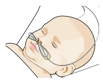
SELECT PATIENT INTERFACE
The AIRVO 2 can be used with a variety of patient interfaces. Read the separate user instructions for the patient interface that will be used, including all warnings.
| Nasal cannula | Tracheostomy interface | Mask interface adapter | |
 |
 |
 |
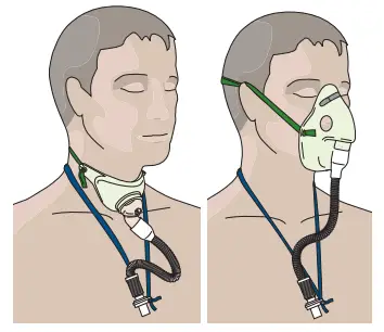 |
| OPT842 OPT844 OPT846 |
VO AIR OPT316, OPT318 (Refer to “Using AIRVO 2” – ”Junior Mode”) | OPT870 | RT013 (with mask) Note that the RT013 Mask Interface Adapter is designed to be used with ented masks only. Do not use sealed masks. |
The following table shows the target dew-point temperature settings and target flow settings able to be used with these interfaces.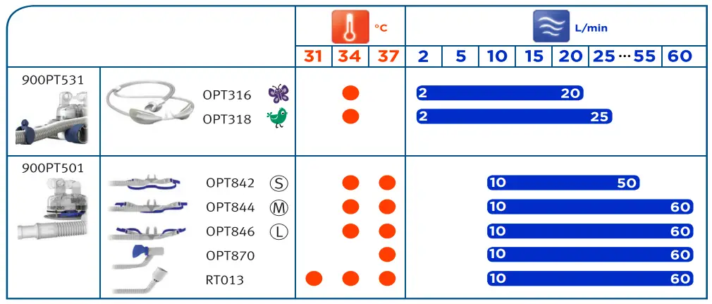
Low-temperature ambient conditions may prevent the unit from reaching a 37 °C target temperature setting at high target flow settings. In these cases, consider decreasing the target flow setting.
WARNINGS
To avoid burns:
- Do not modify the breathing tube or interface in any way.
- Do not use any patient interfaces not listed here.
USING AIRVO 2
SWITCH ON UNIT
Plug the unit’s power cord into the main power supply. The connector at the other end of the power cord should be well secured to the rear of the unit.
WARNINGS
To avoid electric shock:
- Ensure that the unit is dry before plugging into the power socket. Switch on the unit by pressing the On/Off button.
CHECK DISINFECTION STATUS
The unit will show you whether it is safe for use on a new patient.
| This AIRVO 2 is safe for use on a new patient. | |
| This AIRVO 2 has not been cleaned and disinfected since its last use. This AIRVO 2 is NOT safe for use on a new patient. |
WARM-UP
The unit will begin to warm up. You will see numbers showing the current output dew-point temperature, flow and oxygen values. These numbers will pulse until they approach their target settings. This screen is called the “Summary screen”.
JUNIOR MODE
If the patient will be using an Optiflow Junior nasal cannula (OPT316/ OPT318), you must activate Junior Mode.
Junior Mode limits the target settings to 34 °C and 2 – 25 L/min, in increments of 1 L/min.
To activate Junior Mode:
 |
Hold the Mode button for 5 seconds. |
| New target settings The target settings for dew-point temperature and flow will be changed automatically. The colorful icons in the corners of the screen indicate that this unit is in Junior Mode. |
|
| To deactivate Junior Mode, follow the same procedure: hold the Mode button for 5 seconds. |
CONFIGURE TARGET SETTINGS
Press the Mode button to view target settings.
![]() These settings are locked by default.
These settings are locked by default.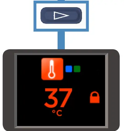
TARGET DEW-POINT TEMPERATURE
You can set the AIRVO 2 to three target dew-point temperature settings:
- 37°C (98.6°F)
- 34°C (93°F) [if compliance at 37°C is a problem]
- 31°C (88°F) [for face masks only].
You may not have access to all settings, if: - the unit is in Junior Mode (limited to 34 °C),
- the unit was initially set up with tighter limits.
The AIRVO 2 will return to its default setting (37°C) after every disinfection cycle.
To change the target dew-point temperature setting:
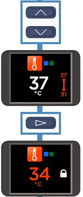 |
Hold the Up and Down buttons for 3 seconds to “unlock” the setting. |
| The lock will disappear and be replaced by an arrow showing the minimum and maximum accessible settings. Press the Up and Down buttons to choose the new setting. | |
| When you have finished, press the Mode button to ‘lock’ the setting again. | |
| The lock will reappear. |
Transport Mode:
![]() If Transport Mode has been enabled, you can activate it on this screen by holding the ”Audio pause” button for 5 seconds. The unit will enter a low-power, low-humidity mode for 20 minutes, designed for use when transporting patients.
If Transport Mode has been enabled, you can activate it on this screen by holding the ”Audio pause” button for 5 seconds. The unit will enter a low-power, low-humidity mode for 20 minutes, designed for use when transporting patients.
For more information, refer to REF 185048130.
To deactivate Transport Mode, follow the same procedure: hold the “Audio pause” button for 5 seconds.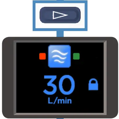
Press the Mode button to move on to the next screen.
TARGET FLOW
You can set the AIRVO 2 to flows between 10 L/min and 60 L/min, in increments of 1 L/min (10-25 L/min) and 5 L/min (25-60 L/min).
You may not have access to all settings, if:
- the unit is in Junior Mode (limited to 2 – 25 L/min, in increments of 1 L/min),
- the unit was initially set up with tighter limits.
The AIRVO 2 will remember its target flow setting when you switch it off.
To change the target flow setting:
Follow the same sequence of steps as above in “To change the target dew-point temperature setting”.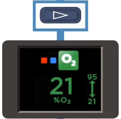
Press the Mode button to move on to the next screen.
OXYGEN
You can connect supplementary oxygen to the AIRVO 2 (up to 60 L/min). The AIRVO 2 contains an oxygen analyzer to help you determine the oxygen fraction you are delivering to the patient. Your unit may have been initially set up with tighter limits.
Use continuous oxygen monitoring on patients who would desaturate significantly in the event of a disruption to their oxygen supply.
![]()
Before using the AIRVO 2 with oxygen, read all of the following warnings:
- The use of oxygen requires that special care be taken to reduce the risk of fire. Accordingly, for safety, it is necessary that all sources of ignition be kept away from the unit and preferably out of the room in which it is being used. Oxygen should not be used while smoking or in the presence of an open flame. The unit should be located in a position where ventilation around the unit is not restricted.
- A spontaneous and violent ignition may occur if oil, grease, or greasy substances come in contact with oxygen under pressure. These substances must be kept away from all oxygen equipment.
- Ensure that the AIRVO 2 is switched on before connecting oxygen.
- Oxygen must only be added through the special oxygen inlet port on the back of the unit. To ensure that oxygen enters the unit correctly, the oxygen inlet port must be fitted properly to the filter holder and the filter holder must be fitted properly to the unit. The power cord connector should also be well secured.
- Do not connect more than 60L/min O2 to the oxygen inlet port on the back of the unit.
- The oxygen concentration delivered to the patient can be affected by changes to the flow setting, oxygen setting, patient interface, or if the airpath is obstructed.
- When finished, turn off the oxygen source. Remove the output of the oxygen source from the oxygen inlet port on the back of the unit. The oxygen flow must be turned off when the unit is not operating so that oxygen does not build up inside the device.
- The oxygen analyzer within the AIRVO 2 uses ultrasonic measurement technology. It does not require in-field calibration. It is designed for use with pure oxygen – connecting any other gases or mixtures of gases will cause it to function incorrectly.
CONNECT OXYGEN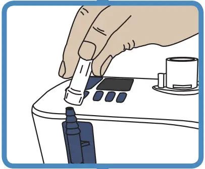
Connect the output from the oxygen source to the oxygen inlet port on the back of the unit. Make sure you push the oxygen tube firmly onto this connection port.
ADJUST OXYGEN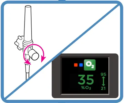
Adjust the level of oxygen from the oxygen source, until the desired oxygen fraction is displayed onscreen. It may take the reading several minutes to settle. You can set the oxygen fraction between the maximum and minimum values displayed above and below the arrow.
If the oxygen fraction exceeds 95%, the oxygen reading will pulse red and the device will beep.
WARNINGS
- Note that if the patient’s peak inspiratory demand exceeds the flow delivered by the unit, the fraction of oxygen inspired by the patient will be lower than the value shown onscreen, due to the additional entrainment of ambient air.
- Check that suitable blood saturation levels are achieved at the prescribed flow.
![]()
Press the Mode button to return to the Summary screen.
6. CONNECT YOUR PATIENT
Wait until the “Ready for use” symbol is displayed on the Summary screen.
![]() The “Ready for use” symbol
The “Ready for use” symbol
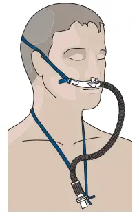
Connect the patient interface to the heated breathing tube.
Monitor the flow and oxygen values displayed on the Summary screen.
Adjust the level of oxygen from the oxygen source as necessary.
When the patient first uses the unit, the air will feel warm. This is normal. The patient should continue to breathe normally through the nose and/or mouth, or tracheostomy.
DURING USE
If the “Ready for use” symbol has been displayed for 1 minute and no button has been pushed in this time, a screensaver will be launched.
If excess condensate accumulates in the heated breathing tube, drain by lifting the patient end of the tube, allowing the condensate to run into the water chamber.
AFTER USE
Switch off the unit by pressing the On/Off button.
ALARMS
The AIRVO 2 has visual and auditory alarms to warn you about interruptions to your patient’s treatment.
These alarms are generated by an intelligent alarm system, which processes information from the sensors and target settings of the unit and compares this information to pre-programmed limits.
ALARM SIGNALS
| Symbols | Meaning | |
| Visual alarm signal | ||
 |
Alarm condition. | |
| Audio paused. | ||
Auditory alarm signal
| 3 beeps in 3 seconds. Repeated every 5 seconds. |
Press this button to mute the auditory alarm for 115 seconds. The auditory alarm can be reactivated by pressing this button again. |
ALARM CONDITIONS
All of the alarms listed below have been assessed as “Medium Priority”. These priorities have been allocated for an operator’s position within 1 meter of the device. The unit also uses an internal priority ranking system. If multiple alarm conditions occur simultaneously, the unit will display the highest-priority alarm.
The following table lists all of the alarm conditions from highest-priority to lowest priority, their causes, possible solutions, and delays. Alarm conditions that affect oxygen delivery require an immediate response to assess the patient’s saturation levels. Alarm conditions that affect humidity delivery require a prompt response to assess the potential drying of mucus and associated blockages.
| Message | Meaning | Affects delivery of: | Delays |
| Fault (E###) | ‘The unit has detected an internal fault and has shut itself down. Switch the unit off and then restart. If the problem persists, note the fault code and contact your Fisher & Paykel Healthcare representative. |
Oxygen, humidity. | < 5 seconds |
| Check tube | The unit cannot detect the heated breathing tube. Check that the heated breathing tube is not damaged and that it is plugged incorrectly. If the problem persists, then change the heated breathing tube. |
Oxygen, humidity. | < 5 seconds |
| Check for leaks | The unit has detected a leak in the system. The most likely cause is that the water chamber has been removed or has not been pushed into place correctly. Check that the heated breathing tube is not damaged and that it is plugged incorrectly. Check that the nasal interface is fitted. Check that the filter is fitted. |
Oxygen, humidity. | < 5 seconds |
| Check for blockages | The unit has detected a blockage in the system. Check the heated breathing tube or patient interface for blockage. Check the air filter and filter holder for blockage. Check whether the unit should be in Junior Mode. If the patient will be using an Optiflow Junior nasal cannula (OPT316/OPT318), you must activate Junior Mode. |
Oxygen, humidity. | <10 seconds |
| 02 too low | The measured oxygen level has fallen below the allowed limit. Check that the oxygen source is still correctly connected. Adjust the level of oxygen from the oxygen source as necessary. | Oxygen | < 20 seconds |
| 02 too high | The measured oxygen level has exceeded the allowed limit. _ Adjust the level of oxygen from the oxygen source as necessary. |
Oxygen | < 20 seconds |
| Message (continued) | Meaning | Affects delivery of: | Delays |
| Cannot reach target flow | The unit cannot reach the target flow setting. Check the heated breathing tube or patient interface for blockage. Check whether the target flow setting is too high for the patient interface being used (refer to “Setting up AIRVO 2” – ”Select Patient Interface”). The unit will choose appropriate new target settings. You will be prompted for acknowledgment. • The oxygen concentration delivered to the patient can be affected by changes to the flow setting. Adjust the level of oxygen from the oxygen source as necessary. |
Oxygen | 10 +/- 1 minutes |
| Check water | The chamber has run out of water. When a chamber runs dry, the chamber float may be damaged. Replace the chamber and water bag. [Twenty seconds after the chamber is removed, the “Check for leaks” alarm is activated (see above). When the chamber is replaced, the unit enters Warm-up Mode and resumes normal operation.] To ensure continual humidification, always ensure that the water chamber and/or water bag are not allowed to run out of water. |
Humidity | Flows above 20 L/min:< 20 minutes Flows of and below 20 L/min: < 40 minutes |
| Cannot reach the target temperature | The unit cannot reach the target temperature setting. You will be prompted for acknowledgment. The most likely cause for this is that the unit is operating at a high flow rate in low ambient conditions. Consider decreasing the target flow setting. • The oxygen concentration delivered to the patient can be affected by changes to the flow setting. Adjust the level of oxygen from the oxygen source as necessary. |
Humidity | 30 +/- 3 minutes |
| Check operating conditions | The unit has detected that it is operating in unsuitable ambient conditions. Do not use the device when the ambient temperature is less than 10°C. Do not use the device when the ambient temperature is greater than 30°C. This alarm may be caused by a sudden change in ambient conditions (eg. storing the unit in a cold place then using it in a warm place). Leave the unit running for 30 minutes. Switch the unit off and then restart. |
Humidity | 60 +/- 6 seconds |
| [Power out] | The unit has been disconnected from the main power supply. No visual alarm. The auditory alarm will sound for 120 seconds. |
Oxygen, humidity. | < 5 seconds |
ALARM LIMITS
Most alarm limits are pre-programmed. The exceptions are listed below. These alarm limits may be changed to other values by authorized personnel. Changes will be preserved during or after any power loss.
| Alarm condition | Factory-set alarm limit | Possible preset values |
| O2 too low | 21% O2 | 21 – 25% O2 |
| O2 too high | 95% O2 | 30 – 100% O2 |
WARNINGS
- A hazard can exist if different alarm presets are used on different units within any single area, eg. an intensive care unit.
- Alarm limits set to extreme values can render the alarm system useless.
CHECKING ALARM SYSTEM FUNCTIONALITY
The functionality of the alarm system can be checked at any time when the unit is turned on.
Remove the heated breathing tube. You should see the “Check tube” visual alarm signal and hear the auditory alarm signal. If either alarm signal is absent, do not use the unit. Contact your Fisher & Paykel Healthcare representative.
AUDITORY INFORMATION SIGNALS
In addition to auditory alarm signals, auditory information signals are provided. These are described below.
| Melody | Meaning |
| Ascending sequence of 5 tones | The “Ready for use” symbol has appeared |
| Ascending sequence of 3 tones | Activation/deactivation of Junior Mode |
| Single-tone every 5 seconds | Measured oxygen level > 95%, OR, Measured oxygen level > 32% at turn-off |
REPROCESSING
The AIRVO 2 must be cleaned and disinfected between patients according to the instructions in the Disinfection Kit Manual (900PT600).
This should take place as soon as possible after use. The unit utilizes warmed water and can pose a risk of bacterial colonization and patient infection if cleaning, disinfection, and replacement procedures are not followed.
Standard aseptic techniques to minimize contamination should be followed when handling the unit and accessories. This includes proper hand-washing, avoiding hand contact with connection ports, safe disposal of the used consumables, and suitable storage of the unit after cleaning and disinfection.
SCHEDULE FOR CHANGING ACCESSORIES
The accessories for the unit must be changed frequently to avoid the risk of infection. Parts should be replaced immediately if they are damaged or discolored; otherwise, they must be replaced within the periods shown in the following table.
| The maximum period of use | Part number and description |
| 1 week (single-patient
use) |
All patient interfaces
OPT316 Nasal Cannula – Infant |
| 2 weeks (single-patient use) | All tube & chamber kits 900PT501 Heated breathing tube, MR290 auto-fill chamber and adapter 900PT531 Heated breathing tube, MR290 auto-fill chamber, and adapter (for use with OPT316/318 only) |
| 3 months or 1000 hours | 900PT913 Air filter (or more often if significantly discolored) |
FILTER REPLACEMENT
If the unit tells you that a filter change is due:
- Take the filter holder from the back of the unit and remove the filter.
- Replace the old filter with a new one.
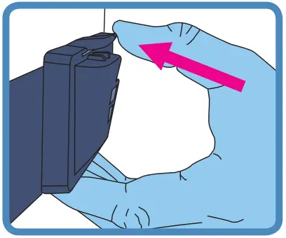
- Reattach the filter holder to the unit (clip the bottom of the filter holder in first, then rotate it upwards until the top clips into place).
- Press the Mode button to move on to the next screen.
SERVICING
This device contains no serviceable parts.
TECHNICAL INFORMATION
SYMBOL DEFINITIONS
| Caution Hot Surfaces | |
 |
Type BF Applied Part |
| ATTENTION Consult accompanying documents | |
| Do not throw away | |
| Drip Proof | |
| ∼ | Alternating Current |
| Class ll Double Insulated | |
| Power On/Off (Standby) | |
| 93/42/EEC Class IIa |
PRODUCT SPECIFICATIONS
| Dimensions | 295 mm x 170 mm x 175 mm (11.6” x 6.7” x 6.9”) |
| Weight | 2.2 kg (4.8 lb) unit only, 3.4 kg (7.5 lb) packaged in bag incl. accessories |
| Supply frequency | 50-60 Hz |
| Supply voltage/current | 100-115 V 2.2 A (2.4 A max) 220-240 V 1.8 A (2.0 A max) |
| Sound pressure level | Alarms exceed 45dbA @ 1 m |
| Auditory alarm pause | 115 seconds |
| Serial port | The serial port is used for downloading product data, using F&P Infosmart™ software. |
| Humidity | >33 mg/L at 37 °C target >10 mg/L at 34 °C target >10 mg/L at 31 °C target |
| Maximum temperature of delivered gas | 43 °C (109 °F) |
| Maximum flow range (default) | 10-60 L/min |
| Maximum flow range (Junior Mode) | 2-25 L/min |
| Maximum oxygen input | 60 L/min |
| Warm-up time | 10 minutes to 31 °C (88 °F), 30 minutes to 37 °C (98.6 °F) using an MR290 chamber with a flow rate of 35 L/min and starting temperature 23 ± 2 °C (73 ± 3 °F) |
| Oxygen analyzer accuracy | < ± (2.5% + 2.5% of gas level) (within the range of 25-95% O2 ) Operating conditions: 18-28 °C (64-82 °F), 30-70% RH |
Designed to conform to the requirements of:
IEC 60601-1
UL 60601-1
CSA C22.2/No. 601.1
AS 3200.1.0
EN 60601-1
The unit complies with the electromagnetic compatibility requirements of IEC 60601-1-2. In certain circumstances, the unit may affect or be affected by nearby equipment due to the effects of electromagnetic interference. If this should happen, try moving the unit or the location of the unit causing interference, or alternatively consult your healthcare provider.
Accessory equipment connected to the serial port of the device must be certified to either IEC 60601-1 or IEC 60950-1. Furthermore, all configurations shall comply with the system standard IEC 60601-1-1. Anyone who connects additional equipment to the signal input part or signal output part configures a medical system and is therefore responsible for ensuring that the system complies with the requirements of the system standard IEC 60601-1-1. If in doubt, consult the technical services department or your local representative.
OPERATING CONDITIONS
| Minimum/maximum ambient temperature | 18 – 28 °C (64 – 82 °F) |
| Humidity | 10 – 95% RH |
| Altitude | 0 – 2000 m (6000 ft) |
| Mode of operation | Continuous operation |
STORAGE AND TRANSPORT CONDITIONS
The unit should be stored and transported in environmental conditions of -10 °C to 60 °C (14 °F to 140 °F), 10 to 95% RH, non-condensing.
DISPOSAL INSTRUCTIONS
 Unit Disposal Instructions This unit contains electronics. Please do not discard with regular waste. Return to Fisher & Paykel Healthcare or dispose of according to local guidelines for disposing of electronics. Dispose of according to Waste Electrical and Electronic Equipment (WEEE) directive in European Union.
![]() Consumables Disposal Instructions Place the interface, breathing tube, and chamber in a waste bag at the end of use. Hospitals should discard according to their standard method for disposing of contaminated products.
Consumables Disposal Instructions Place the interface, breathing tube, and chamber in a waste bag at the end of use. Hospitals should discard according to their standard method for disposing of contaminated products.
For more information please contact your local Fisher & Paykel Healthcare representative
Australia
Fisher & Paykel Healthcare Pty Limited
36-40 New Street,
PO Box 167
Ringwood, Melbourne
Victoria 3134, Australia
Tel: +61 3 9879 5022
Fax: +61 3 9879 5232
Austria
Tel: 0800 29 31 23
Fax: 0800 29 31 22
Benelux
Tel: +31 40 216 3555
Fax: +31 40 216 3554
China
Tel: +86 20 3205 3486
Fax: +86 20 3205 2132
France
Tel: +33 1 6446 5201
Fax: +33 1 6446 5221
Germany
Tel: +49 7181 98599 0
Fax: +49 7181 98599 66
India
Tel: +91 80 4284 4000
Fax: +91 80 4123 6044
Irish Republic
Tel: 1800 409 011
Italy
Tel: +39 06 7839 2939
Fax: +39 06 7814 7709
Spain
Tel: +34 902 013 346
Fax: +34 902 013 379
Sweden
Tel: +46 8 564 76 680
Fax: +46 8 36 63 10
Switzerland
Tel: 0800 83 47 63
Fax: 0800 83 47 54
Taiwan
Tel: +886 2 8751 1739
Fax: +886 2 8751 5625
Turkey
Fisher Paykel Sağlık Ürünleri Ticaret
Limited Şirketi,
Alinteri Bulvari 1161/1 Sokak No. 12-14,
P.O. Box 06371 Ostim,
Ankara, Turkey
Tel: +90 312 354 34 12
Fax: +90 312 354 31 01
UK 
Fisher & Paykel Healthcare Ltd
Unit 16, Cordwallis Park
Clivemont Road, Maidenhead
Berkshire SL6 7BU, UK
Tel: +44 1628 626 136
Fax: +44 1628 626 146
USA/Canada
Tel: +1 800 446 3908
or +1 949 453 4000
Fax: +1 949 453 4001
Manufacturer
Fisher & Paykel Healthcare Ltd
15 Maurice Paykel Place
East Tamaki, Auckland 2013
PO Box 14 348, Panmure
Auckland 1741
New Zealand
Tel: +64 9 574 0100
Fax: +64 9 574 0158
Email: [email protected]
Web: www.fphcare.com
REF 185048127 REV A 2013-June © 2013 Fisher & Paykel Healthcare Limited
![]() 0123
0123
www.fphcare.com