CRAFTMADE UCI-2000-2 Universal Intelligent Control System
GENERAL INFORMATION
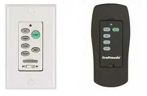
This remote control is designed to separately control your ceiling fan speed and light brightness. There are four buttons to control the fan speed.
The light dimmer button controls the light brightness. The red indicator on the transmitter will light when any button is pressed.
INSTALLATION AND OPERATING INSTRUCTIONS, HANDHELD REMOTE CONTROL
SAFETY PRECAUTIONS
 DANGER: HIGH VOLTAGE! Household electrical power can cause serious injury or death. Disconnect source of electrical power to the ceiling fan by removing fuse or switching off circuit breaker. Make sure all electrical connections comply with local codes, ordinances, the National Electrical Code, and ANSI/NFPA 70-1999. If you are unfamiliar with electrical wiring, please use a qualified and licensed electrician.
- WARNING: To reduce the risk of fire, electrical shock, or personal injury, wire connectors provided with the remote control receiver are designed to accept only one 12-gauge house wire and no more than two lead wires from the receiver. If your house wire is larger than 12-gauge or there is more than one house wire to connect to the two receiver wires, consult an electrician for the proper size wire connectors to use.
- CAUTION: TO REDUCE THE RISK OF FIRE OR ELECTRIC SHOCK, DO NOT USE THE FAN WITH ANY SOLID STATE SPEED CONTROL DEVICE OR CONTROL FAN SPEED WITH A FULL RANGE DIMMER SWITCH.
- Do not use this remote control with solid state ceiling fans, electrical source and fan must be 120 volts, 60 Hz. Maximum fan motor amps: 1.5; Maximum light watts: 300 incandescent Electronic ballast (LED lights or CFL lights) 300VA
- CAUTION: “DO NOT DISPOSE OF BATTERIES IN FIRE, BATTERIES MAY EXPLODE OR LEAK.” –
When disposing of household alkaline batteries, it is best to check with your local and state recycling or household hazardous waste coordinators concerning the specifics of the program in your area. You may also locate a recycling center by calling 1-800-8-BATTERY or 1-877-2-RECYCLE or visit www.epa.gov/epawaste/index.htm or www.earth911.org for more information. - WARNING: Choking Hazard – Small parts. Keep batteries away from children.
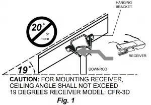
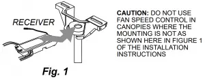
INSTALLATION OF RECEIVER (Please refer to Figure 1 before continuing.)
- Manually set fan speed control to HIGH via pull chain and set light to ON via pull chain.
IMPORTANT: Fan speed and light control will not be activated by remote if pull chains for fan and light are not set to the HIGH and ON positions, respectively. - Disconnect source of electrical power to the ceiling fan by removing fuse or switching off circuit breaker.
- Lower ceiling fan canopy from the hanging bracket.
- Disconnect existing wiring between ceiling fan and supply at electrical outlet box.
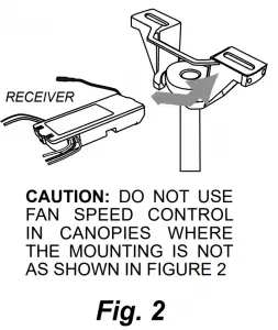
- Lay the black antenna wire on top of the receiver and slide the receiver (flat side up) into the hanging bracket. (Figure 2)
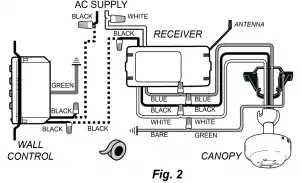
- Using the wire connectors supplied, make wiring connections as follows: (Figure 3)
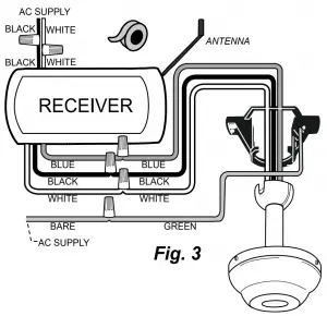
CONNECT: TO: GREEN fan wire BARE supply wire BLACK receiver wire (AC IN L) BLACK supply wire WHITE receiver wire (AC IN N) WHITE supply wire WHITE receiver wire (TO MOTOR N) WHITE fan wire BLACK receiver wire (TO MOTOR L) BLACK fan wire BLUE receiver wire (FOR LIGHT) BLUE light wire (from fan) Wrap each wire connector separately with electrical tape as an extra safety measure. If other fan or supply wires are different colors than those mentioned, have this unit installed by a qualified electrician.
- Push all connected wires up into outlet box. Make sure antenna rests outside of hanging bracket.
- Re-install the canopy on the hanging bracket
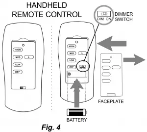
ASSEMBLY OF HANDHELD REMOTE CONTROL
- To use wall control as a handheld remote control, cut each wire on wall control. Use wire cutters to cut off each wire as close to the wall control as possible.
- Place wall control into BOTTOM part of remote control cover, aligning posts in top of remote control cover with post holes in the bottom. Squeeze top and bottom of remote control cover until you hear a click at each end, indicating the remote control cover has closed completely.
- Install 12-volt battery (included). (Figure 4) NOTE: Battery is NOT rechargeable. Remove battery with low or no charge and dispose of properly.
WARNING: Battery is to be inserted with the correct polarity.
CAUTION: Store the handheld remote control away from excess heat or humidity. To prevent damage to handheld remote control, remove the battery if handheld remote control will not be used for long periods.
AUTOMATED LEARNING PROCESS
CAUTION: The transmitter can be programmed to multiple receivers or fans. If this is not desired, turn wall switch off to any other programmable receiver or fan.
- Remove faceplate from transmitter to reveal battery compartment and dimmer switch.
- Setting the dimmer switch:
Locate the dimmer switch above the battery compartment labeled “DIM” and “ON”. Set dimmer switch to ON (DIM) position only if using incandescent bulbs. Set dimmer switch to OFF (ON) position if using LED or compact fluorescent bulbs. NOTE: Most LED or compact fluorescent bulbs are not compatible for use with dimmer controls. - Restore electrical power. Within 30 seconds of restoring electrical power, press the “OFF” button, located on the front of the remote control transmitter, for 5 seconds or until light on fan blinks twice. Test the light and fan functions to confirm the programming (learning process) is complete. (Figure 4)
- Replace faceplate on transmitter. (Figure 4)
TRANSMITTER–CARE AND OPERATION
- If you find that your fan and light kit go on and off without using your remote control, turn power off
and repeat Step D in Section III (Automated Learning Process). - Store the transmitter away from excess heat or humidity.
- To prevent damage to transmitter, remove the battery if not used for long periods.
- Operation buttons on the front panel of the transmitter:
HIGH button for fan HIGH speed / MED button for fan MEDIUM speed / LOW button for fan LOW speed OFF button for fan OFF / L button for light BRIGHTNESS and OFF
The light function is controlled by pressing the L button. Hold button down to increase or decrease light. Tap button quickly to turn light off or on. If you press the button in excess of 0.7 seconds it becomes a dimmer. The light varies cyclically in 0.8 seconds. The light button has auto resume so the light will stay at the same brightness as the last time it was turned off.
INSTALLATION AND OPERATING INSTRUCTIONS, WALL CONTROL
This wall control is designed to separately control your ceiling fan speed and light brightness. There are four buttons (High, Med, Low, Off) to control the fan speed and one button (L1) to control the light. The red indicator on the transmitter will light when any button is pressed.
SAFETY PRECAUTIONS
Please make sure to read “Safety Precautions” on reverse side of page if you have not already done so.
INSTALLATION OF RECEIVER
(Please refer to instructions on reverse side of page if receiver has not yet been installed.)
INSTALLING WALL CONTROL
- Remove wall plate from existing wall switch.
- Disconnect and remove the toggle switch from wall outlet box.
- Using the wire connectors provided, make the electrical connections to the wall control as shown in Figure 2. Wrap each wire connector separately with electrical tape as an extra safety measure.
- Carefully push all connected wires back inside wall outlet box.
- Secure wall control with 2 screws provided. Attach wall plate cover with the 2 original screws.
AUTOMATED LEARNING PROCESS
CAUTION: The wall control can be programmed to multiple receivers or
fans. If this is not desired, turn power off to any other programmable receiver
or fan.
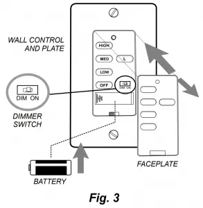
- Remove faceplate to reveal battery compartment and dimmer switch.
- Setting the dimmer switch:
Locate the dimmer switch above the battery compartment labeled “DIM” and “ON”. Set dimmer switch to ON (DIM) position only if using incandescent bulbs.
Set dimmer switch to OFF (ON) position if using LED or compact fluorescent bulbs. (Figure 2)
NOTE: Most LED or compact fluorescent bulbs are not compatible for use with dimmer controls. - Install 12-volt battery (included) IMPORTANT: Wall control will not function unless battery is installed.
NOTE: Battery is NOT rechargeable. Remove battery with low or no charge and dispose of properly. - Restore electrical power, set slider switch on wall control to the ON position.
Within 30 seconds of turning on the wall control, press the “OFF” button, located on the wall control, for 5 seconds or until light on fan blinks twice. Test the light and fan functions to confirm the programming (learning process) is complete. - Replace faceplate on wall control. (Figure 2)
WALL CONTROL–CARE AND OPERATION
- If you find that your fan and light kit go on and off without using your wall control, turn power off and repeat Section IV (Automated Learning Process) above.
- To prevent damage to wall control, remove the battery if not used for long periods of time.
- Operation buttons on the front panel of the wall control (Figure 3):
HIGH button for fan HIGH speed
MED button for fan MEDIUM speed
LOW button for fan LOW speed
OFF button for fan speed OFF
L button for light BRIGHTNESS and OFF
The light function is controlled by pressing the L button. Hold button down to increase or decrease light. Tap button quickly to turn light off or on. If you press the button in excess of 0.7 seconds it becomes a dimmer. The light varies cyclically in 0.8 seconds. The light button has auto resume, so the light will stay at the same brightness as the last time it was turned off.
TROUBLESHOOTING GUIDE
A. Remote and/or wall control fails to operate:
- Make sure there is power to the receiver.
- Make sure the receiver is wired correctly.
- Make sure that the fan is set on the highest speed via pull chain.
- Make sure the light kit is turned on via pull chain.
- Make sure the battery/batteries in the remote/wall control is/are good.
- The learning process between fan and remote and/or wall control may not have been successful. Turn power off and repeat Section IV, C in “Automated Learning Process” on reverse side of page for remote control or Section IV, D in “Automated Learning Process” above for wall control.
B. Transmitter won’t operate at a distance:
If transmitter operates fan and light kit when up close but not at 40 feet away, try placing the black antenna wire higher and make sure the black antenna wire is visible.
| CAUTION:
TO REDUCE THE RISK OF FIRE OR ELECTRIC SHOCK, DO NOT USE THE FAN WITH ANY SOLID STATE SPEED CONTROL DEVICE OR CONTROL FAN SPEED WITH A FULL RANGE DIMMER SWITCH. |