CTEK DC/DC Battery Charger D250SE
SAFETY
CALIFORNIA PROPOSITION 65
WARNING: This product contains chemical known to the state of California to cause cancer or reproductive toxicity.
- The D250SE and SMARTPASS 120S have been developed for 12V lead-acid and LFP batteries. Do not use the unit for any other type of battery.
- Wear protective goggles when connecting and disconnecting batteries.
- Battery acid is corrosive. Rinse with plenty of water immediately if you get acid on your skin or in your eyes. Get medical assistance.
- Never use a charger with damaged electric cables. Check that the cables have not been dama-ged by hot surfaces, sharp edges or in any other way.
- Explosive gases are generated while lead-acid batteries are being charged. Avoid any sparking near the battery. Use in a well-ventilated location.
- Never place the charger above the battery, and avoid covering the charger during charging.
- Disconnect the battery terminal posts before installing.
- The D250SE and SMARTPASS 120S are not spark-free.
- The installation must include a fuse in accordance with the recommendations in the table “CABLE AND FUSE RECOMMENDATIONS”.
Remember that all installations in boats must comply with ISO 10133!
- The cabling from the batteries must have fuses near the batteries.
- The batteries must be securely fastened in a ventilated space.
- The cabling must be run through pipe ducting, separately from 230V/110V wiring (mains power), or secured by clips at every 30 cm/1 ft.
- Cabling in the engine compartment must be temperature rated at 70°C/ 158°F.
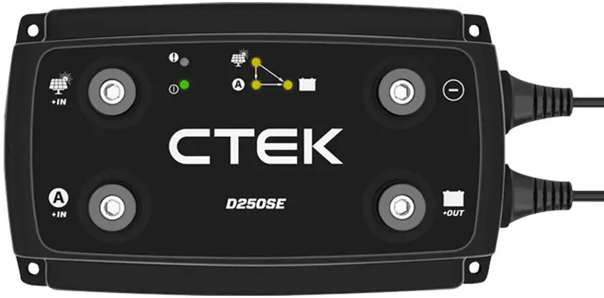
D250SE
- The D250SE is a DC to DC battery charger for a dual battery system with a starter battery and a service battery.
- The D250SE charges the service battery either from an alternator or from a solar panel, or from a combination of both.
- The D250SE separates the batteries in a dual battery system and thereby replaces, for example, a separation relay, VSR (Voltage Sensitive Relay), diode isolator or a mechanical battery selector.
- The D250SE can be used on its own or in combination with SMARTPASS 120S. In combination, the D250SE and SMARTPASS 120S can charge at up to 140A.
- Starter battery is only available as lead-acid battery.
FUNCTIONS
- Charging service battery from a conventional alternator (constant charging voltage)
The D250SE charges a service battery at up to 20A from the start battery when a conventional alternator is running. This function is switched off when the engine is not running to prevent discharge of the starter battery. - Charging of a service battery from a smart alternator (with variable charging voltage)
The D250SE can charge a service battery at up to 20A from the starter battery when a smart alternator is running. This function is switched off when the engine is not running, so as not to discharge the starter battery. The Installation section describes how the D250SE needs to be con-nected in order to activate the smart alternator functions. - Charging a service battery from a solar panel
The D250SE can charge and trickle charge a service battery from a solar panel at up to 20A. The D250SE uses MPPT (Maximum Power Point Tracker) to maximise the power from the solar panel. - Separation of the starter battery and the service battery
The D250SE separates the starter battery from the service battery when the engine is not running. - Temperature compensated charge voltage
The D250SE optimises the charge voltage by increasing the charge voltage at temperatures below 25°C/77°F and reducing it at temperatures higher than 25°C/77°F. The function is active in AGM and NORMAL programs only. - Trickle charging of the starter battery from a solar panel
The D250SE trickle charges the starter battery from a solar panel at intervals of 3 seconds if the service battery is fully charged. - Optimised charging of AGM batteries
The D250SE can provide a suitable charging voltage for optimal charging of AGM (Absorbent Glass Mat) batteries, which require a higher charge voltage than other types of lead-acid battery. The installation section describes how the D250SE needs to be connected in order to activate the AGM battery function. - Optimised charging of Lithium batteries
The D250SE can provide a suitable charging voltage for optimal charging of Lithium batteries.
SMARTPASS 120S
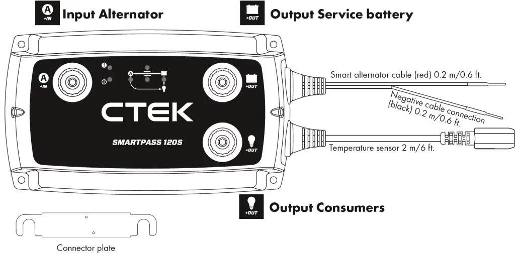
- SMARTPASS 120S is a solution for supplying current to charge and manage consumers in a dual battery system consisting of a starter battery and a service battery.
- SMARTPASS 120S separates the batteries in a dual battery system and thereby replaces, for exam-ple, a separation relay, VSR (Voltage Sensitive Relay), diode isolator or a mechanical battery selector.
- SMARTPASS 120S connects the starter and service batteries together in order to charge them both from the alternator.
- SMARTPASS 120S protects the service battery from deep discharge which would damage the battery.
- SMARTPASS 120S supplies consumers from the alternator instead of from the service battery while the service battery is charging, which permits faster charging.
- SMARTPASS 120S can be used on its own or in combination with D250SE. In combination, the D250SE and SMARTPASS 120S can charge at up to 140A.
FUNCTIONS
- Charging service battery from a conventional alternator (constant charging voltage)
The SMARTPASS 120S charges a service battery at up to 120A from the start battery when a conventional alternator is running. This function is switched off when the engine is not running to prevent discharge of the starter battery. - Charging of a service battery from a smart alternator (with variable charging voltage)
The SMARTPASS 120S can charge a service battery at up to 120A from the starter battery when a smart alternator is running. This function is switched off when the engine is not running, so as not to discharge the starter battery. The Installation section describes how the SMARTPASS 120S needs to be connected in order to activate the smart alternator functions. - Battery guard
SMARTPASS 120S disconnects consumers when the service battery voltage is low in order to avoid deep discharge, which would damage the battery. The consumers are reconnected after the service battery voltage has increased. Connect critical consumers directly to the service battery so they will not be disconnected if the voltage falls to lower than 11.5V. - Start assistance
SMARTPASS 120S automatically connects the service battery to the starter battery for 10 sec to assist, if the starter battery on its own is unable to start the engine. After the start assistance func-tion has been activated, SMARTPASS 120S will display a fault indication until starting has been achieved without using the start assistance function. - Separation of the starter battery and the service battery
SMARTPASS 120S separates the starter battery from the service battery when the engine is not running. - Assigning current source priority
SMARTPASS 120S can sense when the alternator is running and in that case supplies consumers with current from the starter battery to work with the D250SE and maximise charging efficiency. Otherwise the consumers are supplied with current from the service battery. - Dynamic overcurrent protection
SMARTPASS 120S has overcurrent protection to shield the product. Overcurrent protection permits up to 350A to be sent from the alternator temporarily so that charging will be accelerated. - Battery temperature protection
SMARTPASS 120S protects the battery by switching off charging if the service battery temperature rises too high. - Starter battery trickle charging
The service battery trickle charges the starter battery without assistance from the solar panel or alternator to compensate for the self-discharge of the starter battery. The service battery charges in
3- second pulses when its voltage is higher that of the starter battery and the voltage of the starter battery is low.
CABLE AND FUSE REQUIREMENTS
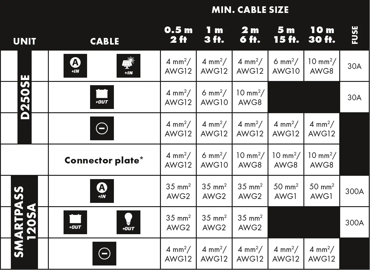
*If the D250SE and SMARTPASS 120S are installed in different locations and the accompanying connector plate is not used, please follow the recommendations in the table.
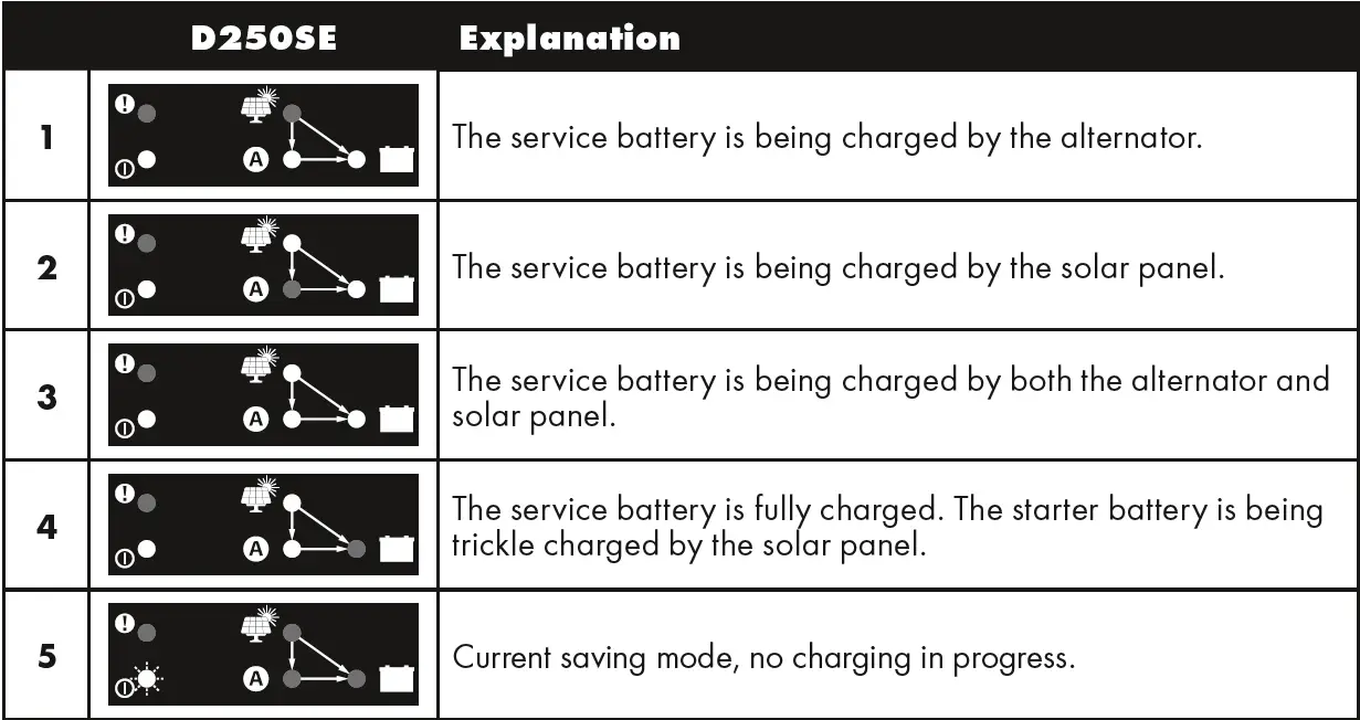
FUNCTION INDICATIONS
D250SE
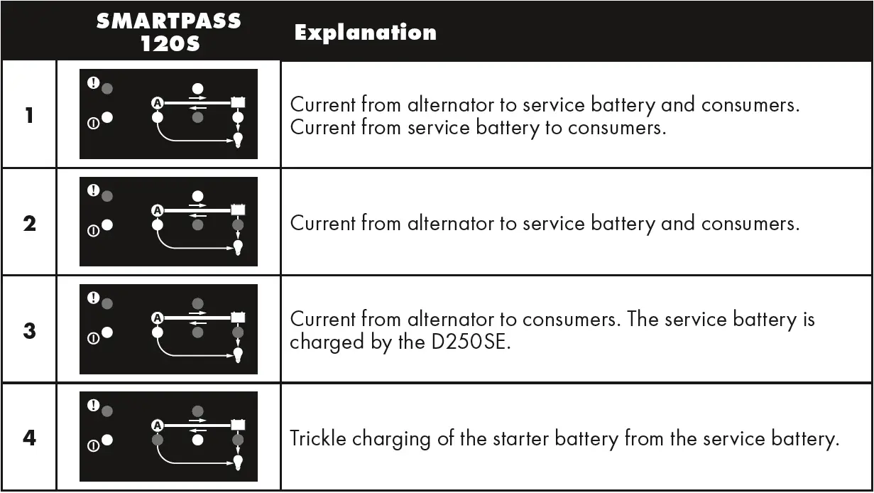
SMARTPASS 120S
INSTALLATION
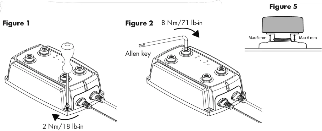
- Install the apparatus on a smooth surface where it can be fi rmly secured and where it is not exposed to fuel, oil or dirt. To obtain the correct distance, start by fi tting the two units together with the accompanying connector plate before they are fi nally fastened to the smooth surface.
- Secure the apparatus with, for example, M4 or ST4.2 screws at each corner.
- Before connecting the cables, ensure that the negative terminal post on the battery is not connected.
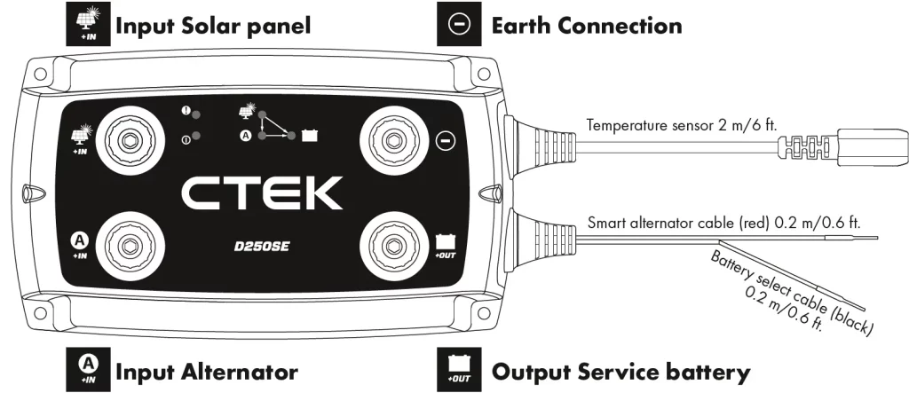
- Connect the cables to the apparatus connections by securing screws (M8).
Use an Allen key – tightening by hand without a tool is not enough. Max 6 mm ring terminals. - Use tape to secure the temperature sensorto a clean flat surface above the service battery. Position the sensor as close to the positive terminal post as possible.
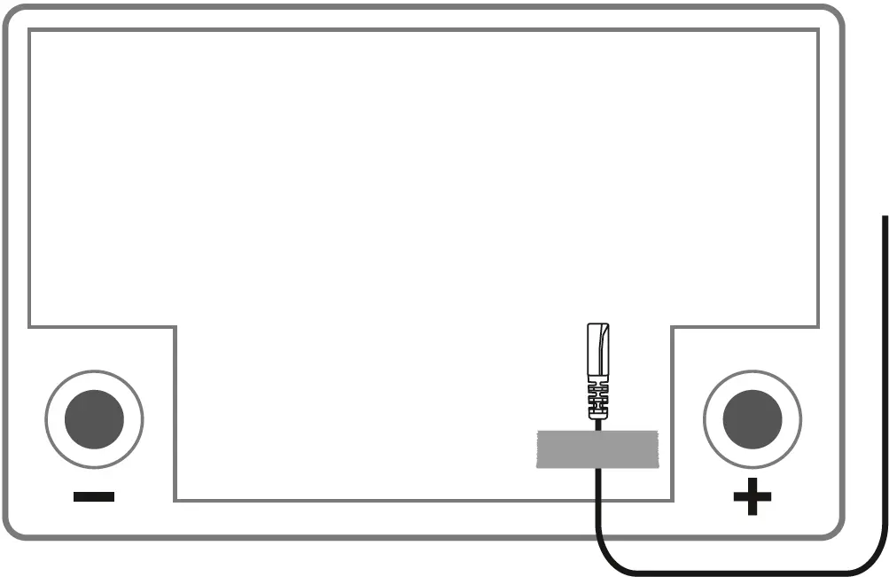
- Connect the battery negative terminal post.
RECOMMENDED TIGHTENING TORQUES
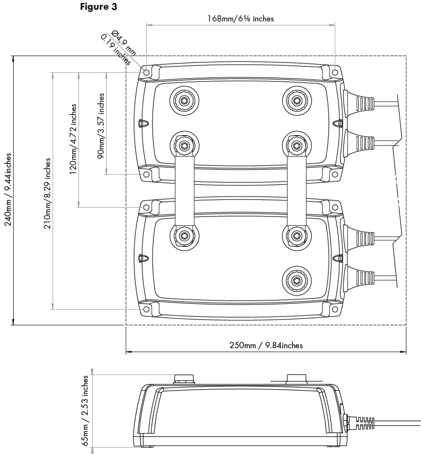
DIMENSIONS
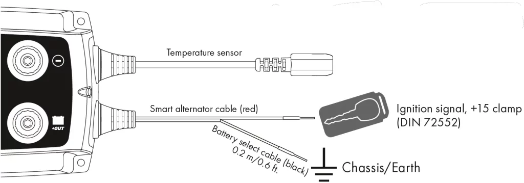
SETTINGS D250SE
| Smart alternator Cable (Red) | Type of Alternator | Battery Select Cable (Black) | Battery Type |
| Not connected | Conventional alternator | Not connected | NORMAL |
| Connected | Smart alternator | Earth | AGM |
| +12V | LITHIUM-ION | ||
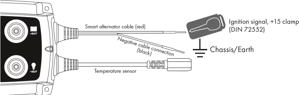
SETTINGS SMARTPASS 120S
| Smart alternator Cable (Red) | Type of Alternator |
| Not connected | Conventional alternator |
| Connected | Smart alternator |
INSTALLATION EXAMPLES
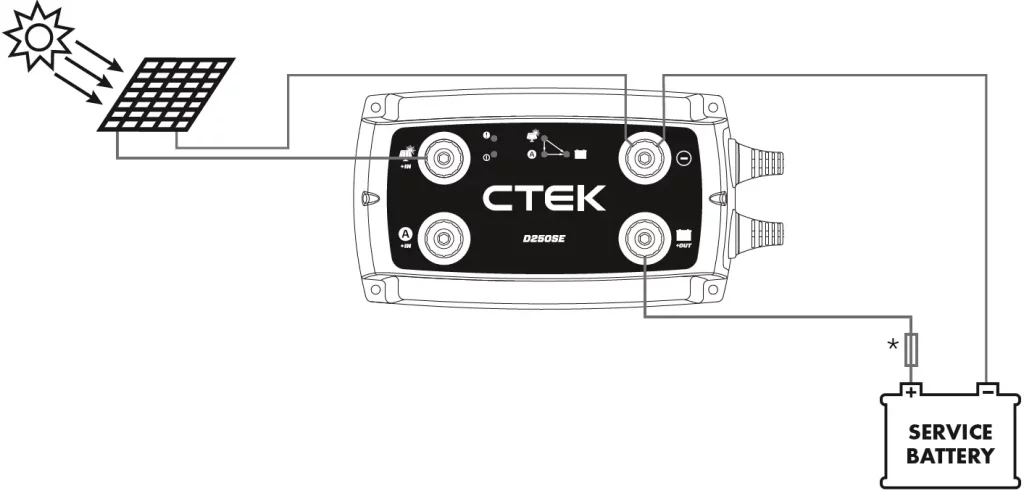
- Solar Panel
PREREQUISITES
Solar panel capable of charging a 40–300Ah service battery. The D250SE uses MPPT (Maximum Power Point Tracker) to maximise the power from a solar panel.
TIP 1: Do not connect two solar panels in series. Max. input voltage 23V.
- Small Service Battery
PREREQUISITES
A dual battery system where the D250SE charges a 40–300Ah service battery from a generator which also charges a starter battery.
It is advantageous to use this installation when:- The alternator is unable to deliver the desired charging voltage.
TIP 2: If the alternator has external voltage detection for the service battery, the voltage detection wiring must be connected to the starter battery.
TIP 3: Complement the D250SE with a SMARTPASS 120S if the service battery capacity is greater than 100Ah or has parallel consumption while charging is in progress. This reduces the charging time.
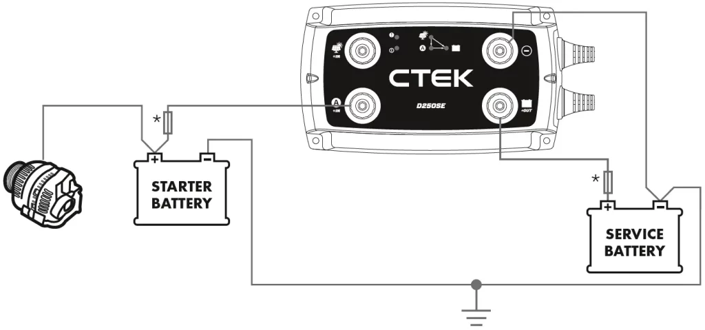
- The alternator is unable to deliver the desired charging voltage.
- Small Service Battery and Solar Panel
PREREQUISITES
A dual battery system where the D250SE char-ges a 40–300Ah service battery from a solar panel, an alternator, or both which also charge a starter battery.
It is advantageous to use this installation when:- The alternator is not able to deliver the desired charge voltage.
- Charging from a solar panel.
See also tips 1, 2 and 3.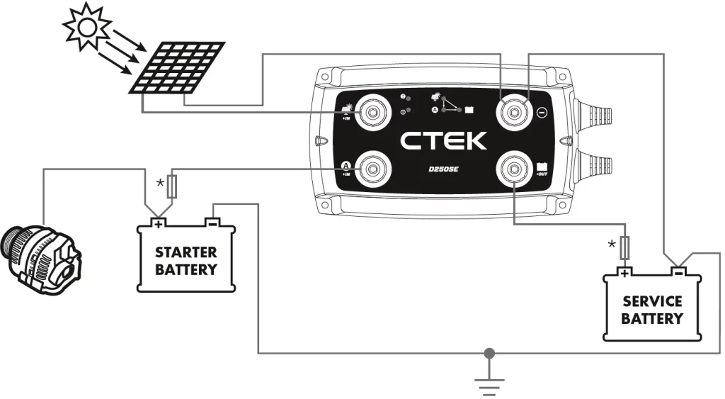
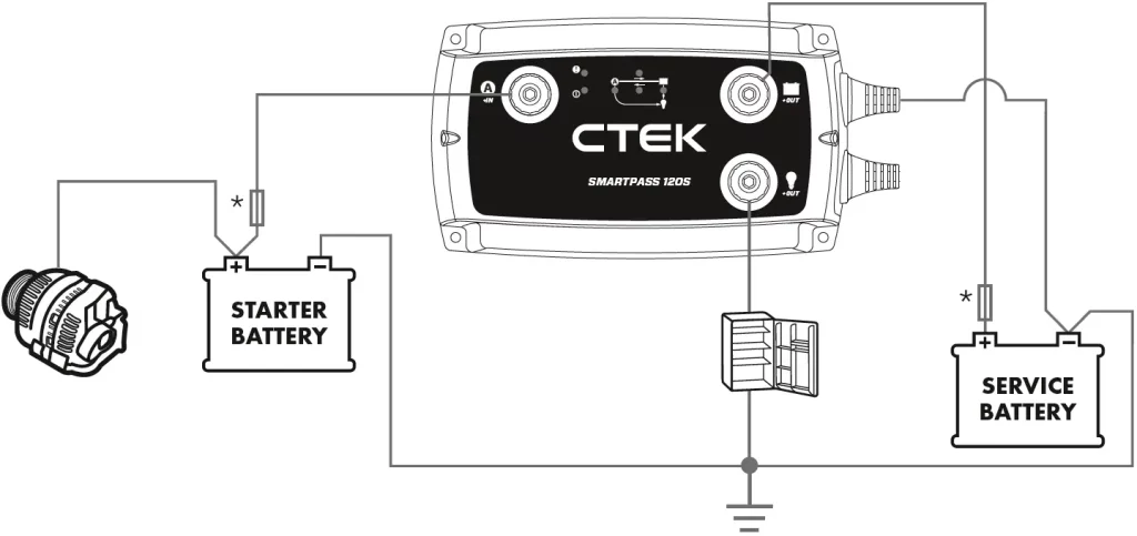
- Service Battery with Parallel Consumers
PREREQUISITES
A dual battery system where the SMARTPASS 120S charges a 28–800Ah service battery from a alternator which also charges a starter battery.
It is advantageous to use this installation when:- The alternator is able to deliver the desired charging voltage.
- The service battery capacity is greater than 100 Ah.
- The consumers are supplied directly from the alternator at the same time as the service bat-tery is being charged.
See also tips 2 and 3.
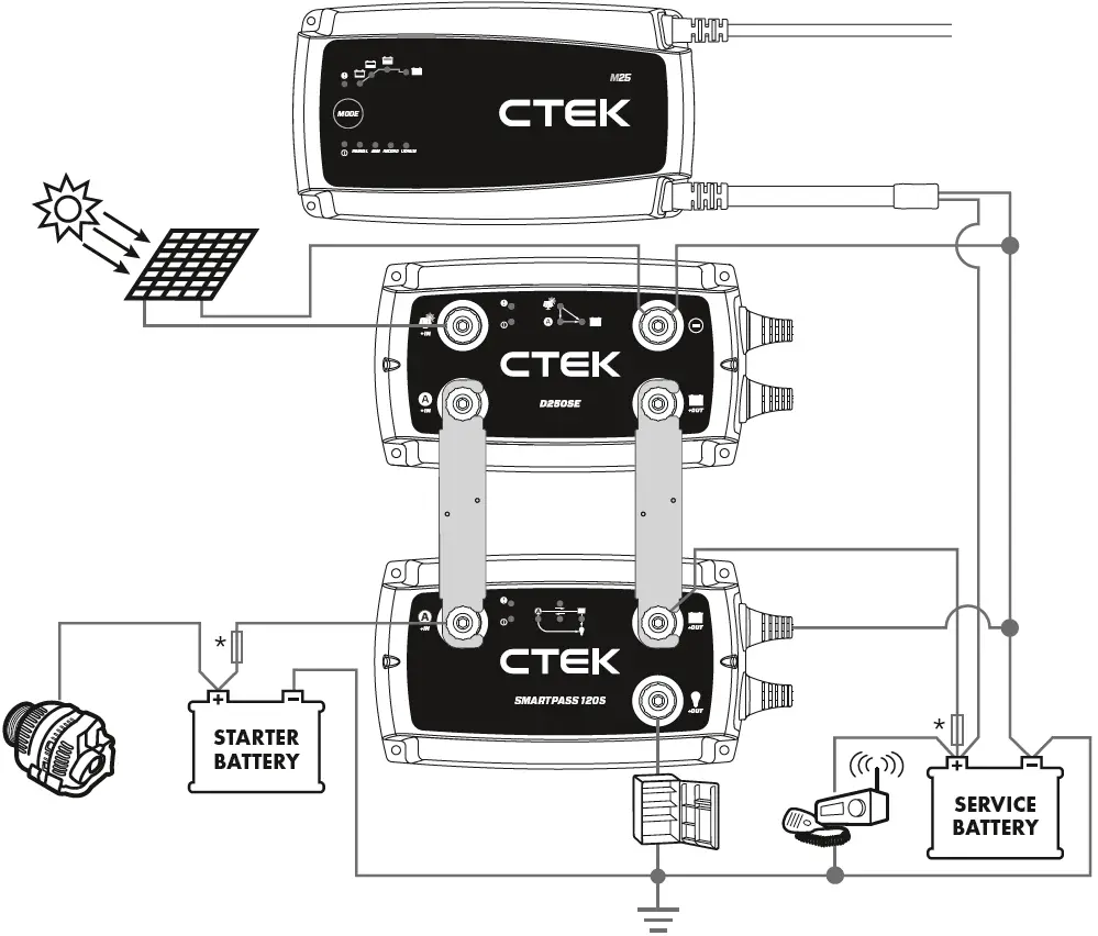
- Large Service Battery with Parallel Consumers
PREREQUISITES
A dual battery system where a D250SE together with a SMARTPASS 120S charges a 100–800Ah service battery. Current is supplied from a solar panel and/or an alternator. The starter battery is charged from an alternator.
It is advantageous to use this installation when:- The alternator is not able to deliver the desired charging voltage.
- The service battery capacity is greater than 100Ah.
Parallel consumption takes place during charging. By connecting the consumers (See TECHNICAL SPECIFICATION) to the Output Consumers on the SMARTPASS 120S, the servi-ce battery will be able to charge without parallel consumption and the consumers will instead be supplied with current from the alternator.- The service battery shall be protected against deep discharge. Connect non-critical consumers to the Output Consumers on the SMARTPASS 120S. Connect critical consumers directly to the service battery. SMARTPASS 120S does not in that case switch off the critical consumers when the service battery is completely discharged.
TIP 4: Connect the cabling from the starter and service batteries respectively to the SMARTPASS 120S and not to the D250SE.
See also tips 1, 2 and 3.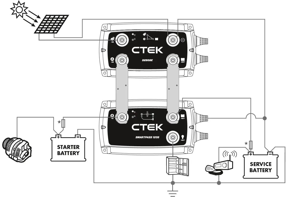
- The service battery shall be protected against deep discharge. Connect non-critical consumers to the Output Consumers on the SMARTPASS 120S. Connect critical consumers directly to the service battery. SMARTPASS 120S does not in that case switch off the critical consumers when the service battery is completely discharged.
- Connect an AC/DC Charger
PREREQUISITES
A dual battery system where there is a 230/110V charger and a D250SE that, together with a SMARTPASS 120S, charge a service battery with a capacity of 150–800Ah. Current is supplied from a solar panel and/or an alternator to the service battery. The starter battery is charged from an alternator.
It is advantageous to use this installation when:- The charge from the alternator while it is char-ging (engine running) is not enough, so it has to be supplemented by a 230/110V charger.
- The alternator is not able to deliver the desired charge voltage.
- The service battery capacity is greater than 150Ah.
- Parallel consumption while charging is taking place. By connecting the consumers (see TECHNICAL SPECIFICATION) to the Output Consumers on the SMARTPASS 120S, the service battery will be able to charge without pa-rallel consumption and the consumers will instead be supplied with current from the alternator.
TIP 5: Connect a 230/110V charger to the starter battery if it needs charging. In that case both the starter and service batteries will be optimally charged from the 230/110V charger.
TIP 6: Heavy current consumers (see TECHNICAL SPECIFICATION) must be connected directly to the service or starter battery.
See also tips 1, 2, 3 and 4.
D250SE CHARGING PROGRAM LEAD-ACID
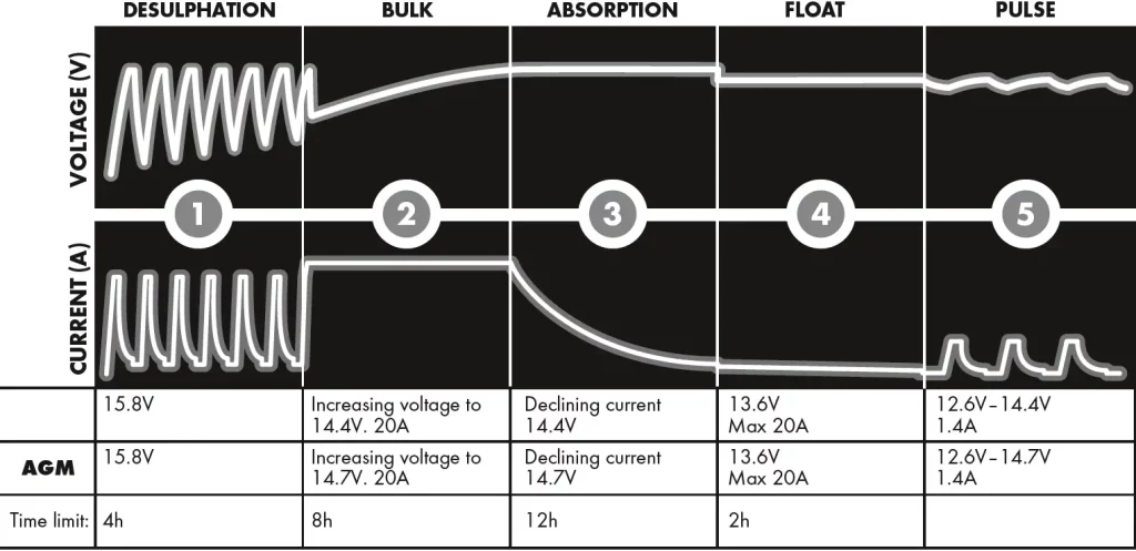
- STEP 1 DESULPHATION
Detects sulphated batteries. Pulsing current and voltage, removes sulphate from the lead plates of the battery restoring the battery capacity. - STEP 2 BULK
Charging with maximum current until approximately 80% battery capacity. - STEP 3 ABSORPTION
Charging with declining current to maximize up to 100% battery capacity. - STEP 4 FLOAT
Maintaining the battery voltage at maximum level by providing a constant voltage charge. - STEP 5 PULSE
Maintaining the battery at 95–100% capacity. The charger monitors the battery voltage and gives a pulse when necessary to keep the battery fully charged.
D250SE CHARGING PROGRAM LITHIUM
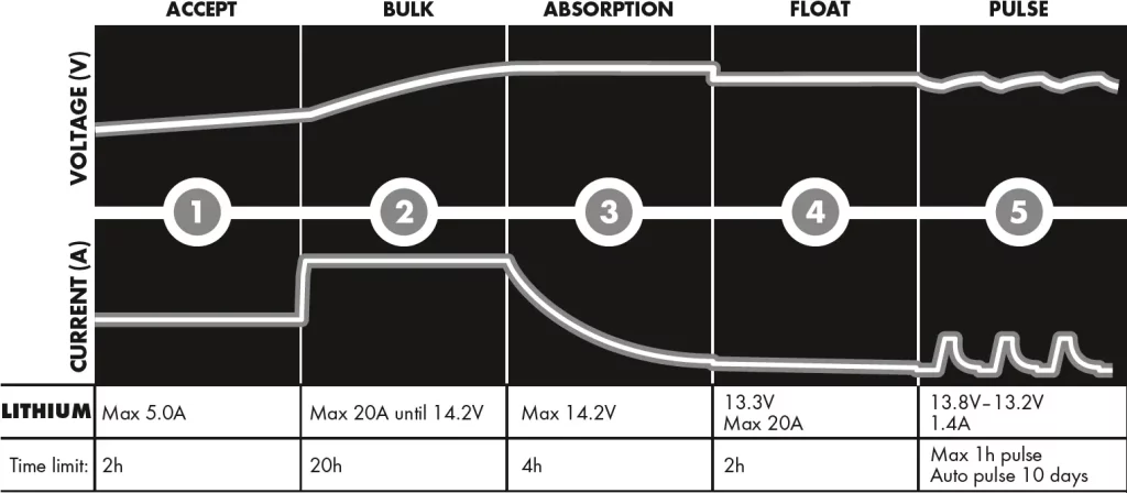
- STEP 1 ACCEPT
Tests if the battery can accept charge. This step prevents that charging proceeds with a defect battery. - STEP 2 BULK
Charging with maximum current until approximately 90% battery capacity. - STEP 3 ABSORPTION
Charging with declining current to maximize up to 95% battery capacity. - STEP 4 FLOAT
Maintaining the battery voltage at maximum level by providing a constant voltage charge. - STEP 5 PULSE
Maintaining the battery at 95–100% capacity. The charger monitors the battery voltage and gives a pulse when necessary to keep the battery fully charged.
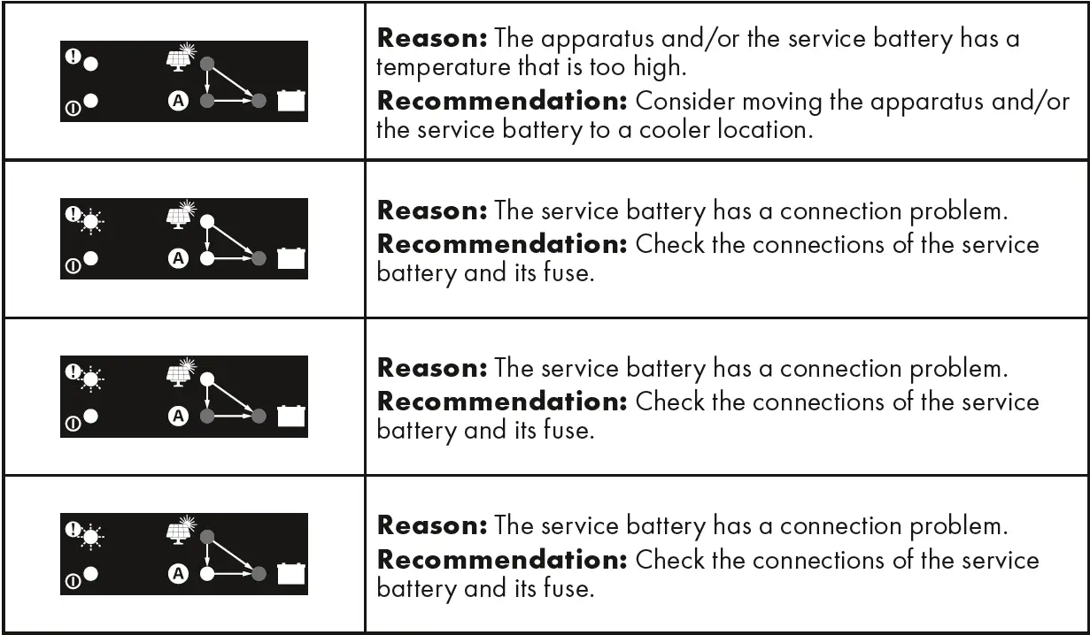
D250SE FAULT INDICATIONS
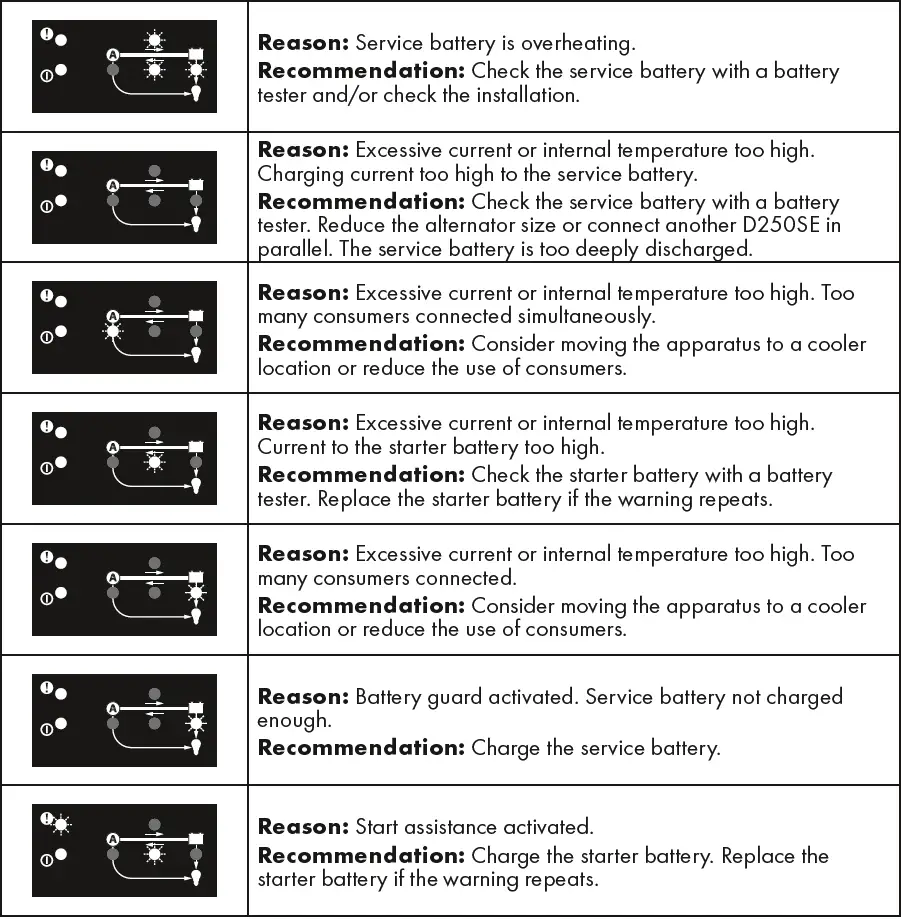
SMARTPASS 120S FAULT INDICATIONS
TECHNICAL SPECIFICATION
| PRODUCT D250SE SMARTPASS 120S | ||
| Model number | 1044 | 1058 |
| Input | 11.5–23V, 25A (Max OCV solar panel 23V) | 11.5–23V, Max 120A (350A temporarily for 10 seconds.) |
| Output battery | Max 14.4V (Normal), 14.2V (Litihum-ion), 14.7V (AGM), 20A | Max. 23V, 120A continuously up to 350A in obout 30 seconds |
| Output consumer | Max. 23V, 80A | |
| Back current drain | Less than 1Ah/month | Less than 7Ah/month |
| Ripple* | Less than 4% | Not applicable |
| Ambient temperature | -20°C to +50°C (-4°F to +122°F) | |
| Power reduction | 30°C 16A, 50°C 13A | |
| Temperature-compensated charging voltage | 23 mV/°C from 25°C/77°F | |
| Battery types | All types of 12V lead-acid batteries (WET, EFB, Ca/Ca, MF, AGM and GEL) 12V (4cells) Lithium-ion batteries (Li-FePO4, Li-Fe, Li-iron, LFP) | |
| Battery capacity | 40–300Ah | 28–800Ah |
| Dimensions | 192 x 110 x 65mm (L x W x H) | |
| Enclosure class | IP65 (splash and dust proof) | |
| Weight | 0.7 kg (1.5 lbs) | |
| Maximum solar panel power | 50–300 W (Max OCV solar panel 23V) | |
| MPPT** | Yes | No |
| Conventional alternator cut-in | >13.1V, for 5 sec. (engine running, alternator charging) | |
| Conventional alternator cut-out | <12.8V, for 10 sec. (engine running, alternator not charging) | |
| Smart alternator cut-in | >11.8V, for 5 sec. (engine running, alternator charging) | |
| Smart alternator cut-out | <11.4V, for 10 sec. (engine running, alternator not charging) | |
| Battery guard cut-in | <11.5V | |
| Battery guard cut-out | >12.0V | |
| Temperature protection cut-in | >60°C (140°F) | |
| Start assistance activation | Starter battery <6V | |
| Trickle charge starter battery | Starter battery 11.5V–12.6V. | |
*) The quality of the charge voltage and charge current is very important. A high current ripple heats up the battery which has an aging effect on the positive electrode. High voltage ripple could harm other equipment that is connected to the battery. CTEK battery chargers produce very clean voltage and current with low ripple.
**) MPPT (Maximum Power Point Tracker) finds the best combination of current and voltage so that the output power is maximised.
LIMITED WARRANTY
CTEK issues this limited warranty to the original purchaser of this product. This limited warranty is not transferable. The warranty applies to manufacturing faults and material defects. The customer must return the product together with the receipt of purchase to the point of purchase. This warranty is void if the product has been opened, handled carelessly or repaired by anyone other than CTEK or its authorised representatives. One of the screw holes in the bottom of the product may be sealed. Removing or damaging the seal will void the warranty. CTEK makes no warranty other than this limited warranty and is not liable for any other costs other than those mentioned above, i.e. no consequential damages. Moreover, CTEK is not obligated to any warranty other than this warranty.
SUPPORT
Visit: www.ctek.com for support, FAQ, the most recent version of the user instructions and further information concerning CTEK products.