![]()
Danby Portable Air Conditioner DPA120BCCWDB

Welcome to the Danby family.
We are proud of our quality products and we believe in dependable service. We suggest that you read this owner’s manual before plugging in your new appliance as it contains important operation information, safety information, troubleshooting, and maintenance tips to ensure the reliability and longevity of your appliance.
You are entitled to the warranty coverage as described in the owner’s manual provided with your new appliance.
- Please write down your appliance information below. You must keep the original proof of purchase receipt to validate and receive warranty services.
- Register your product online and receive a FREE 2 MONTH WARRANTY EXTENSION after fi lling out a product survey, at www.danby.com/support/product-registration/
Need Help?
- Read your Owner’s Manual for installation help, troubleshooting, and maintenance assistance.
- Visit www.Danby.com to access self-service tools, FAQs and much more by searching your model number in the search bar.
- For the Quickest Customer Service, please fi ll out the web form at www.danby.com/support. Your submission will go directly to an expert on your particular appliance. Our average response times are between 20 minutes and 2 hours, during EST business hours.
- Call 1-800-263-2629 – please note that during peak hours, hold times can exceed one hour.
Important Safety Information
READ AND FOLLOW ALL SAFETY INSTRUCTIONS
SAFETY REQUIREMENTS
DANGER: Risk of fi re or explosion. Flammable refrigerant used. Do not damage the refrigerant circuit.
- Ensure that servicing is done by factory authorized service personnel, to minimize product damage or safety issues.
- Consult repair manual or owner’s guide before attempting to service this product. All safety precautions must be followed.
- Dispose of properly in accordance with federal or local regulations.
- Follow handling instructions carefully.
- Keep ventilation openings, in the appliance clear of obstruction.
- Do not use mechanical devices or other means to accelerate the defrosting process.
- Children should be supervised to ensure that they do not play with the appliance.
- Do not store or install the appliance near continuously operating ignition sources such as open flames or a gas stove.
- Do not operate near water or in a wet room.
- Do not pierce or burn.
- Be aware that refrigerants may not contain an odor.
- The appliance must be stored so as to prevent mechanical damage from occurring.
All wiring must comply with local and national codes and must be installed by a qualifi ed electrician. Check the available power supply and resolve any wiring problems before installing and operating this appliance.
The rating plate located on the right side of the appliance just above the power cord contains electrical and other technical data.
This appliance is not intended for use by persons (including children) whose physical, sensory or mental capabilities may be different or reduced, or who lack experience or knowledge, unless such persons receive supervision or training to operate the appliance by a person responsible for their safety.
GROUNDING INSTRUCTIONS
This appliance must be grounded. Grounding reduces the risk of electrical shock by providing an escape wire for the electrical current.
This appliance has a cord that has a grounding wire with a 3-prong plug. The power cord must be plugged into an outlet that is properly grounded. If the outlet is a 2-prong wall outlet, it must be replaced with a properly grounded 3-prong wall outlet. The serial rating plate indicates the voltage and frequency the appliance is designed for.
WARNING – Improper use of the grounding plug can result in a risk of electric shock.
Consult a qualifi ed electrician or service agent if the grounding instructions are not completely understood, or if doubt exists as to whether the appliance is properly grounded.
Do not connect your appliance to extension cords or together with another appliance in the same wall outlet. Do not splice the power cord. Do not under any circumstances cut or remove the third ground prong from the power cord. Do not use extension cords or ungrounded (two prongs) adapters.
If the power supply cord is damaged, it must be replaced by the manufacturer, its service agent or similar qualifi ed person in order to avoid hazard.
CAUTION: RISK OF FIRE
Flammable refrigerant used. When maintaining or disposing of the air conditioner, the refrigerant must not be allowed to vent into the open air.
Any person involved with working on the refrigerant circuit should hold a current, valid certifi cate from an industry accredited assessment authority which authorizes their competence to handle refrigerants safely in accordance with an industry recognized assessment specifi cation.
Servicing shall only be performed as recommended by the manufacturer. Maintenance and repair requiring the assistance of other skilled personnel shall be carried out under the supervision of the person competent in the use of flammable refrigerants.
When maintaining or disposing of the appliance the refrigerant must be recovered properly and should not be allowed to discharge to the air directly.
Information on servicing
- Checks to the area: Prior to beginning work on systems containing flammable refrigerants, safety checks are necessary to ensure that the risk of ignition is minimized. For repair to the refrigerating system, the following precautions shall be complied with prior to conducting work on the system.
- Work procedure: Work shall be undertaken under a controlled procedure so as to minimize the risk of flammable gas or vapour being present while the work is being performed.
- General work area: All maintenance staff and others working in the local area shall be instructed on the nature of work being carried out. Work in confi ned spaces shall be avoided. The area around the work space shall be sectioned off. Ensure that the conditions within the work area have been made safe by removing all flammable material.
- Checking for the presence of refrigerant: The area shall be checked with an appropriate refrigerant detector prior to and during work to ensure the technician is aware of potentially flammable atmospheres. Ensure that the leak detection equipment being used is suitable for use with flammable refrigerants, i.e. non-sparking, adequately sealed and intrinsically safe.
- Presence of fi re extinguisher: If any hot work is to be conducted on the refrigeration equipment or any associated parts, appropriate fi re extinguishing equipment shall be available
to hand. Have a dry powder or C02 fire extinguisher adjacent to the work area. - No ignition sources: No person carrying out work in relation to a refrigeration system which involves exposing any pipe work that contains or has contained flammable refrigerant shall use any sources of ignition in such a manner that it may lead to risk of fi re or explosion. All possible ignition sources including cigarette smoking, should be kept suffi ciently far away from the site of installation, repairing, removing and disposal during which flammable refrigerant can possibly be released to the surrounding space. Prior to work taking place, the area around the equipment is to be surveyed to make sure there are no flammable hazards or ignition risks. No smoking signs shall be displayed.
- Ventilated area: Ensure that the area is in the open or that it is adequately ventilated before breaking into the system or conducting any hot work. A degree of ventilation shall continue during the period that the work is carried out. The ventilation should safely disperse any released refrigerant and preferable expel it externally into the atmosphere.
- Checks to the refrigeration equipment: Where electrical components are being changed, they shall be fi t for the purpose and to the correct specifi cation. At all times the manufacturer’s maintenance and service guidelines shall be followed. If in doubt consult the manufacturer’s technical department for assistance.
The following checks shall be applied to installations using flammable refrigerants:
- The charge size is in accordance with the room size within which the refrigerant containing parts are installed.
- The ventilation machinery and outlets are operating adequately and are not obstructed.
- If an indirect refrigerating circuit is being used, the secondary circuit shall be checked for the presence of refrigerant.
- Marking to the equipment continues to be visible and legible. Markings and signs that become illegible must be corrected.
- Refrigeration pipe or components are installed in a position where they are unlikely to be exposed to any substance which may corrode refrigerant containing components, unless the components are constructed of materials which are inherently resistant to being corroded or are suitable protected against being corroded.
- Checks to electrical devices: Repair and maintenance to electrical components shall include initial safety checks and component inspection procedures. If a fault exists that could compromise safety, then no electrical supply shall be connected to the circuit until it is satisfactorily dealt with. If the fault cannot be corrected immediately but it is necessary to continue operation, an adequate temporary solution shall be used. This shall be reported to the owner of the equipment so all parties are advised.
Initial safety checks shall include:
- That capacitors are discharged. This shall be done in a safe manner to avoid possibility of sparking.
- That no live electrical components and wiring are exposed while charging, recovering or purging the system.
- That there is continuity of earth bonding.
Repairs to sealed components
- During repairs to sealed components, all electrical supplies shall be disconnected from the equipment being worked upon prior to any removal of sealed covers, etc. If it is absolutely necessary to have an electrical supply to equipment during servicing then a permanently operating form of leak detection shall be located at the most critical point to warn of a potentially hazardous situation.
- To ensure that by working on electrical components the casing is not altered in such a way that the level of protection is affected, particular attention shall be paid to the following:
- Damage to cables, excessive number of connections, terminals not made to original specifi cation, damage to seals, incorrect fitting of glands, etc.
- Ensure the apparatus is mounted securely.
- Ensure that seals or sealing materials have not degraded such that they no longer serve the purpose of preventing the ingress of flammable atmospheres. Replacement parts shall be in accordance with the manufacturer’s specifi cations.
Note: The use of silicon sealant may inhibit the effectiveness of some types of leak detection equipment. Intrinsically safe components do not have to be isolated prior to working on them.
Repair to intrinsically safe components
Do not apply any permanent inductive or capacitance loads to the circuit without ensuring that this will not exceed the permissible voltage and current permitted for the equipment in use. Intrinsically safe components are the only types that can be worked on while live in the presence of a flammable atmosphere. The test apparatus shall be at the correct rating. Replace components only with parts specifi ed by the manufacturer. Other parts may result in the ignition of refrigerant in the atmosphere from a leak.
Cabling
Check that cabling will not be subject to wear, corrosion, excessive pressure, vibration, sharp edges or any other adverse environmental effects. The check shall also take into account the effects of aging or continual vibration from sources such as compressors or fans.
Detection of fl ammable refrigerants
Under no circumstances shall potential sources of ignition be used in the searching for or detection of refrigerant leaks. A halide torch or any other detector using a naked fl ame shall not be used.
Leak detection methods
The following leak detection methods are deemed acceptable for systems containing fl ammable refrigerants:
- Electronic leak detectors shall be used to detect fl ammable refrigerants but the sensitivity may not be adequate or may need recalibration. Detection equipment shall be calibrated in a refrigerant-free area. Ensure that the detector is not a potential source of ignition and is suitable for the refrigerant used.
- Leak detection equipment shall be set at a percentage of the LFL of the refrigerant and shall be calibrated to the refrigerant employed and the appropriate percentage of gas (25%maximum) is confi rmed.
- Leak detection fl uids are suitable for use with most refrigerants but the use of detergents containing chlorine shall be avoided as the chlorine may react with the refrigerant and corrode the copper or pipe-work.
- If a leak is suspected, all naked fl ames shall be removed or extinguished.
- If a leakage of refrigerant is found which requires brazing, all of the refrigerant shall be recovered from the system or isolated by means of shut off valves in a part of the system remote from the leak. Oxygen free nitrogen (OFN) shall then be purged through the system both before and during the brazing process.
Removal and evacuation
When breaking into the refrigerant circuit to make repairs or for any other purpose conventional procedures shall be used. However, it is important that the best practice is followed since fl ammability is a consideration. The following procedures shall be adhered to:
- Remove refrigerant.
- Purge the circuit with inert gas.
- Evacuate.
- Purge again with inert gas.
- Open the circuit by cutting or brazing.
- The refrigerant charge shall be recovered into the correct recovery cylinders. The system shall be fl ushed with OFN to render the unit safe. This process may need to be repeated several times. Compressed air or oxygen shall not be used for this task.
- Flushing shall be achieved by breaking the vacuum in the system with OFN and continuing to fi ll until the working pressure is achieved, then venting to atmosphere and finally pulling down to a vacuum. This process shall be repeated until no refrigerant is within the system. When the final OFN charge is used, the system shall be vented down to atmospheric pressure to enable work to take place. This operation is absolutely vital is brazing operations on the pipe-work are to take place.
- Ensure that the outlet for the vacuum pump is not close to any ignition sources and there is ventilation available.
Charging procedures
In addition to conventional charging procedures, the following requirements shall be followed:
- Ensure that contamination of different refrigerants does not occur when using charging equipment. Hoses or lines shall be as short as possible to minimize the amount of refrigerant contained in them.
- Cylinders shall be kept upright.
- Ensure that the refrigeration system is earthed prior to charging the system with refrigerant.
- Label the system when charging is complete, if not already labeled.
- Extreme care shall be taken not to overfi ll the refrigeration system.
- Prior to recharging the system it shall be pressure tested with OFN. The system shall be leak tested on completion of charging but prior to commissioning. A follow up leak test shall be carried out prior to leaving the site.
Decommissioning
Before carrying out this procedure, it is essential that the technician is completely familiar with the equipment in all its detail. It is recommended good practice that all refrigerants are recovered safely. Prior to the task being carried out, an oil and refrigerant sample shall be taken in case analysis is required prior to re-use of reclaimed refrigerant. It is essential that electrical power is available before the task is commenced.
A. Become familiar with the equipment and its operation.
B. Isolate system electrically.
C. Before attempting the procedure ensure that:
• Mechanical handling equipment is available if required for handling refrigerant cylinders.
• All personal protective equipment is available and being used correctly.
• The recovery process is supervised at all times by a competent person.
• Recovery equipment and cylinders conform to the appropriate standards.
D. Pump down refrigerant system, if possible.
E. If a vacuum is not possible, make a manifold so that refrigerant can be removed from various parts of the system.
F. Make sure that cylinder is situated on the scales before recovery takes place.
G. Start the recovery machine and operate in accordance with the manufacturer’s instructions.
H. Do not overfi ll cylinders. No more than 80%volume liquid charge.
I. Do not exceed the maximum working pressure of the cylinder, even temporarily.
J. When the cylinders have been fi lled correctly and the process is completed, make sure that the cylinders and the equipment are removed from the site promptly and all isolation valves on the equipment are closed off.
K. Recovered refrigerant shall not be charged into another refrigeration system unless it has been cleaned and checked.
Labeling
Equipment shall be labeled stating that it has been decommissioned and emptied of refrigerant. The label shall be dated and signed. Ensure that there are labels on the equipment stating the equipment contains fl ammable refrigerant.
Recovery
When removing refrigerant from a system, either for servicing or decommissioning, it is recommended good practice that all refrigerants are removed safely.
When transferring refrigerant into cylinders, ensure that only appropriate refrigerant recovers cylinders are employed. Ensure that the correct number of cylinders for holding the total system charge are available. All cylinders to be used are designed for the recovered refrigerant and labeled for that refrigerant, i.e. special cylinders for the recovery of refrigerant. Cylinders shall be complete with pressure relief valve and associated shut-off valves in good working order. Empty recovery cylinders are evacuated and, if possible, cooled before recovery occurs.
The recovery equipment shall be in good working order with a set of instructions concerning the equipment that is at hand and shall be suitable for the recovery of fl ammable refrigerants. In addition, a set of calibrated weighing scales shall be available and in good working order. Hoses shall be complete with leak-free disconnect couplings and in good condition. Before using the recovery machine, check that is it in satisfactory working order, has been properly maintained and that any associated electrical components are sealed to prevent ignition in the event of a refrigerant leak. Consult the manufacturer if in doubt.
The recovered refrigerant shall be returned to the refrigerant supplier in the correct recovery cylinder and the relevant waste transfer note shall be arranged. Do not mix refrigerants in recovery units and especially not in cylinders. If compressors or compressor oils are to be removed, ensure that they have been evacuated to an acceptable level to make certain that fl ammable refrigerant does not remain within the lubricant. The evacuation process shall be carried out prior to returning the compressor to the suppliers. Only electric heating to the compressor body shall be employed to accelerate this process. When oil is drained form a system, it shall be carried out safely.
INSTALLATION INSTRUCTIONS
ACCESSORIES
- Air outlet adapter
- Exhaust hose
- Window slider adapter
- 8 bolts
- Window slider A and B
- Window slider C and D
- Foam seal A and B (adhesive)
- Foam seal C (non-adhesive)
- Remote control and batteries

REQUIRED TOOLS
- Medium sized Phillips screwdriver
- Tape measure or ruler
- Knife or scissors
- Saw (in the event that the window sliders need to be cut to size)
ASSEMBLING THE WINDOW KIT
- Attach the air outlet adapter and the window slider adapter onto either end of the exhaust hose.
- Insert the air outlet adapter into the back of the appliance by placing over the air exhaust and then pushing in the direction of the arrow to lock into place.
- Measure the window opening where the window kit will be installed. Assemble as many sliders as necessary to fi t the window. If the length of the window requires all three sliders, use two bolts to fasten the sliders at the correct length. If the window opening is less that the minimum length of a single slider, use the slider that has the hole in it and cut it to the correct length. Make sure not to cut the end that has the hole as this is necessary to attach the exhaust hose adapter.

INSTALLING THE WINDOW KIT
The window kit can be used in either a hung window or a sliding window application. The images at the right are for a hung window. The steps for a sliding window are the same.
- Cut the adhesive foam seals A and B to the correct length for the window. Attach them to the window sash and frame as shown.
- Insert the assembled window slider kit into the window opening.
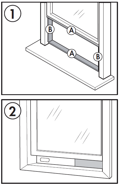
- Cut the non-adhesive foam seal C to match the width of the window. Insert the foam seal between the glass and the window frame to prevent air and insects from getting into the room.
- Attach the window slider adapter to the hole in the window slider kit.


Note: It may be easier to attach the window slider adapter to the window slider kit before placing the kit in the window.
Note: Do not over extend or bend the hose as this will impede air flow.

IMPORTANT WARNING:
Do not leave this appliance unattended in a space where people or animals who cannot react to a malfunction are located. A malfunction such as the exhaust hose becoming dislocated, can cause extreme overheating or death in an enclosed, unattended space.
OPERATING INSTRUCTIONS
FEATURES
Front
1. Control panel
2. Handle (both sides)
3. Air exhaust
4. Casters

Rear
1. Air intake
2. Air outlet
3. Continuous drain
4. Air intake
5. Lower drain
6. Power cord

LOCATION
Place the air conditioner on a smooth, level fl oor that is strong enough to support it and all included accessories.
Make sure the appliance is level to minimize noise and vibration.
The appliance must be installed near a grounded receptacle and the overfl ow drain outlet on the rear of the appliance must be accessible.
Do not cover air inlets or outlets or the remote control receiver on the control panel.
The appliance requires 45 cm (17.7 inches) of clearance on the front and sides.

The appliance requires at least 50 cm (20 inches) of clearance on the back.

CONTROL PANEL
- Timer button: Used to set the automatic timer.
- Fan button: Used to choose the fan speed.
- Temperature control buttons: Used to increase or decrease the set temperature.
- Mode button: Used to choose the mode; cool, fan or dry.
- Power button: Used to turn the appliance on or off.
Note: Certain functions can only be accessed through the remote control.

OPERATING MODES
Cool Mode
- Press the mode button to choose cool mode.
- Use the temperature control buttons to choose the desired temperature.
- Use the fan button to choose the desired fan speed.
- The temperature can be set within a range of 18 – 32°C (64 – 90°F).
- The exhaust hose should be installed during cool mode to ensure the best results.
Dry Mode
- Press the mode button to choose dry mode.
- The fan speed will be set to auto.
- The exhaust hose should be installed during dry mode to ensure the best results.
Fan Mode
- Press the mode button to choose fan mode.
- Press the fan button to choose the desired fan speed.
- The exhaust hose does not need to be installed during fan mode.
TIMER
The timer function can be used to turn the appliance on or off after a period of time to conserve energy.
To set the timer to turn the appliance off:
- While the appliance is running, press the timer button. The time display will fl ash.
- Press the timer button to choose the number of hours before the appliance will turn off.
- Wait 5 seconds to confi rm the setting. The timer icon will illuminate.
To set the timer to turn the appliance on:
- Turn the appliance on and choose the desired mode and settings. Turn the appliance off.
- While the appliance is turned off, press the timer button. The time display will fl ash.
- Press the timer button to choose the number of hours before the appliance will turn on.
- Wait 5 seconds to confi rm the setting. The timer icon will illuminate.
Notes: Turning the appliance on or off at any time or adjusting the timer setting to 0 hours will cancel the timer settings.
CHILD LOCK
The child lock can be activated by pressing the temperature control buttons on the remote control at the same time for 3 seconds. The buttons on the remote control cannot be used while the child lock is active. To deactivate the child lock, press and hold the temperature control buttons at the same time for 3 seconds.
The child lock can only be activated or deactivated using the remote control.
SLEEP
The sleep function can be used to conserve energy during sleeping hours. The sleep function can only be used during cool mode.
When selected, the set temperature will increase by 1 degree per hour for 2 hours. The appliance will hold the new set temperature for 6 hours before automatically returning to normal operation.
The sleep function can only be activated with the remote control and can be canceled at any time by pressing the sleep button.
REMOTE CONTROL
- Power button: Used to turn the appliance on or off.
- Turbo button: The turbo feature is not available on this model.
- Temperature control buttons: Used to increase or decrease the set temperature.
- Timer button: Used to set the timer function.
- Mode button: Used to choose the mode.
- Swing button: The swing feature is not available on this model.
- Sleep button: Used to set the sleep function.
- Fan button: Used to set the fan speed.
- °C/°F button: Used to change the temperature scale between Celsius and Fahrenheit.

Note: The remote control will function within a range of 7 meters (23 feet) of the appliance.
REMOTE DISPLAY
The digital display on the remote control will show the below symbols. Please note that not all features may be available on your model. If you try to use a feature that your model does not support, the appliance will default to fan mode.

REPLACING THE REMOTE BATTERIES
This air conditioner comes with two AAA batteries. Place the batteries in the remote control before use.
- Slide the back cover from the remote downward to expose the battery compartment.
- Insert the batteries, ensure to match the (+) and (-) symbols on the ends of the batteries with the symbols inside the battery compartment.
- Slide the battery cover back into place.
Notes:
- The air conditioner will not respond if curtains, doors or other materials block the signal from the remote control to the unit.
- Prevent any liquid from contact with the remote control. Do not expose the remote control to direct sunlight or heat.
- If the infrared signal receiver on the indoor unit is exposed to direct sunlight, the air conditioner may not function properly. Use curtains to prevent the sunlight from falling on the receiver.
- Do not mix old and new batteries or batteries of different types.
- Do not leave the batteries in the remote control if it is not going to be used for more than 2 months.

This equipment has been tested and found to comply with the limits for a Class B digital device, pursuant to Part 15 of the FCC Rules. These limits are designed to provide reasonable protection against harmful interference in a residential installation. This equipment generates, uses and can radiate radio frequency energy and, if not installed and used in accordance with the instructions, may cause harmful interference to radio communications. However, there is no guarantee that interference will not occur in a particular installation.
If this equipment does cause harmful interference to radio or television reception, which can be determined by turning the equipment off and on, the user is encouraged to try to correct the interference by one or more of the following measures:
- Reorient or relocate the receiving antenna
- Increase the separation between the equipment and receiver
- Connect the equipment into an outlet on a circuit different from that to which the receiver is connected
- Consult the dealer or an experienced radio/TV technician for help
Changes or modifi cations not approved by the party responsible for FCC compliance could void the user’s authority to operate the equipment. This appliance complies with Part 15 of the FCC Rules.
Operation is subject to the following conditions:
- This device may not cause harmful interference.
- This device must accept any interference received, including interference that may cause undesired operation.
This device complies with Canadian CAN ICES-3 (B) / NMB-3 (B)
IMPORTANT: Do not dispose of batteries as unsorted municipal waste. Refer to local laws for proper disposal of batteries.
WATER DRAINAGE
When the internal drain pan becomes full the appliance will stop operating and the display will show error code “Ft”. The air conditioning or dehumidifying action will stop but the fan may continue to operate.
Drain Plug
- Turn the appliance off and unplug it from the power source.
- Carefully move the appliance to a location where the water can be drained.
- Remove the drain plug and allow the water to completely drain.
- Replace the bottom drain plug, pressing fi rmly to ensure a tight fi t and no leaks.
- The “Ft” error symbol will disappear and the appliance will resume regular function once power is restored.

CARE and MAINTENANCE
CLEANING
- Unplug the appliance before cleaning or servicing.
- Clean the cabinet with a lukewarm damp cloth and neutral detergent. Dry the cabinet with a lint-free dry cloth.
- Do not use gasoline, paint thinner or other chemicals to clean the appliance.
- Do not wash the appliance directly under a tap or using a hose. It may cause electrical damage.
AIR FILTER
The filter in this appliance should be cleaned every two weeks to ensure efficient performance.
In households with animals, the air filters may need to be cleaned more often and the external grills may need to be wiped to prevent blocked air flow.

LONG-TERM STORAGE
- Drain all water from the appliance.
- Run the appliance on fan mode for half a day in a warm room to dry the inside of the appliance and prevent mold formation.
- Turn off the appliance and unplug it, wrap the cord and bundle it with tape.
- Remove the battery from the remote control.
- Clean the air fi lters and reinstall them.
- Store the appliance in a cool, dark place. Prolonged exposure to direct sunlight or extreme heat can shorten the lifespan of the appliance.
DISPOSAL
This appliance should not be treated as regular household waste. Check for local regulatory compliance regarding the approved and safe disposal of this appliance.
Do not dispose of batteries as unsorted municipal waste. Refer to local laws for proper disposal of batteries.
ERROR CODES
Lt – low temperature – the appliance will pause functioning if ice forms on the internal structure; the appliance will resume normal functioning automatically when the ice melts
PF – sensor failure – unplug the appliance for 5 minutes to reset the internal sensors; if the error code persists after plugging the appliance back in, please contact consumer care for servicing information
Ft – water tray is full
Odors
Odour is caused by the formation of mold or mildew on internal surfaces. This can happen when there is poor air circulation, a dirty filter or the air conditioner was not used for a period of time.
- Ensure the filter is clean.
- Run the unit on fan mode to remove any internal moisture.
- Check for any blockages in the drain lines and ensure there are no obstructions.
Please give your unit a hard reboot. Unplug it and plug it back in after 15-20 minutes. This allows the unit to warm and drain if there is any frost stopping draining and go back to factory settings
For odour in a unit, we suggest using an algaecide tablet. You fi rst need to turn the unit off, remove the lower grill and fi lter from the grill at the base of the unit, and then place the tablet in base.
TROUBLESHOOTING
Appliance will not operate
- Plug is not fully inserted into the wall outlet
- Blown fuse or circuit breaker
Insufficient cooling
- Air filter is dirty
- Blocked airflow
- Appliance size is too small for application
Noise
- The ground is not level
- The air filter is dirty or blocked
- Gurgling sounds are normal, this is coolant moving inside the appliance
Odors
- Formation of mold or mildew on internal wet surfaces
- Place an algaecide tablet in the base pan; ensure the appliance is unplugged, remove the upper grille and filter, place the tablet in the middle water tray and replace the grille and filter
LIMITED IN-HOME APPLIANCE WARRANTY
This quality product is warranted to be free from manufacturer’s defects in material and workmanship, provided that the unit is used under the normal operating conditions intended by the manufacturer.
This warranty is available only to the person to whom the unit was originally sold by Danby Products Limited (Canada) or Danby Products Inc. (U.S.A.) (hereafter “Danby”) or by an authorized distributor of Danby, and is non-transferable.
TERMS OF WARRANTY
Plastic parts are warranted for thirty (30) days from the date of purchase, with no extensions provided.
First 24 months
During the first twenty four (24) months, any functional parts of this product found to be defective, will be repaired or replaced, at warrantor’s option, at no charge to the original purchaser.
To obtain service
Contact the dealer where the unit was purchased, or contact the nearest authorized Danby service depot, where service must be performed by a qualified service technician. If service is performed on the unit by anyone other than an authorized service depot, all obligations of Danby under this warranty shall be void.
Boundaries of in-home service
Danby reserves the right to limit the boundaries of “In Home Service” to the proximity of an authorized service depot. Any appliance requiring service outside the limited boundaries of “In Home Service”, will be the consumer’s responsibility to transport at their own expense to the original point of purchase or a service depot for repair. If the appliance is installed in a location that is 100 kilometers (62 miles) more from the nearest service center, it must be delivered to the nearest authorized Danby Service Depot by the purchaser.
Transportation charges to and from the service location are not protected by this warranty and are the responsibility of the purchaser.
FAQs
Can I leave my DPA120BCCWDB AC in place through the winter?
This is not recommended.
What are the standard wattage and amps used?
Information pertaining to watts and amps can be found on the rating plate located on the side of the unit.
When should I use the exhaust hose?
The exhaust hose should be used in cool, dry, heat and auto modes. It is not required in fan mode.
Can I use an extension cord?
No, an extension cord may not be used.
Can I extend the length of the exhaust hose?
No. The unit was designed with the length of the hose in mind and has only been tested under those conditions. Instead use an additional fan to blow the cool air to other locations.
When should I use the drain hose?
The drain hose should be used in heat mode, dry mode or if using the continuous drain.
Where do I drain water from?
The water drains from the drainage port. If you are not using the continuous drain, the internal pan drains from the bottom outlet.
What is the difference between a Portable Air Conditioner and a window air conditioner?
A window air conditioner is designed to be installed in an existing window. A portable air conditioner is designed to be moved from room to room.
Can I install my portable air conditioner in a window?
No, you cannot install your portable air conditioner in a window. It must be placed on a flat, level surface.
How do I calculate the square feet of the space I would like to cool?
Square feet is calculated by multiplying the length by the width. For example, a room that is 10 feet long by 25 feet wide is 250 square feet.
Why does my unit have three draining ports?
Units with three drainage ports are units which also feature heat mode. The bottom drainage port empties the internal pan, the middle port is for continuous drain during heat and the top port is for continuous drain during dry mode. Please consult your owner’s manual for more detail.
What are the differences between the dual hose model and the single hose?
Dual hose models have an intake and exhaust hose. With single hose models, the hose exhausts and the air that is to be conditioned is taken in from the room through the unit.
How can I prevent heat from escaping from my Danby Portable Air Conditioner hose?
There are a few things to check to ensure this doesn’t happen: Ensure that the hose is properly installed at both ends and this should minimize heat escape. Ensure the hose is not over extended. Keep the unit as close the window/patio as possible. Ensure the unit is in an area where it’s getting lots of air circulation, which allows the unit to run cooler and results in less heat escaping. If the heat is escaping from the exhaust port then the hose is either restricted or not installed properly. Unfortunately, it is not possible to completely stop all heat loss from escaping.
What does automatic mode mean?
When automatic mode is selected, this automatically sets the appropriate option for your room based on the set temperature and the ambient temperature. For example, if it is 15°C outside, the unit would flip to fan mode if the set temperature was above 15. If it is set to 25°C the unit would revert to cooling mode. The unit would not revert to cooling mode unless the temperature outside was over 25.
Why is my air conditioner not cooling my entire apartment?
Danby air conditioners are designed to cool a single room and not multiple rooms. Any walls or doors will interfere with the air flow.

