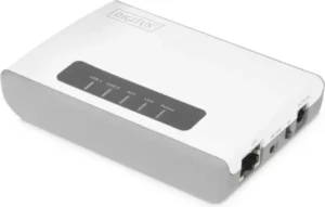
2-PORT USB 2.0 WIRELESS MULTI-

Manual
DN-13024
Safety Precautions
- Only use the device within the specified temperature range for: 0 ~ 40°C
- When not in use, store the product in a clean and dry place in temperatures between 0°C and 40°C
- Do not let the indoor devices come into contact with liquids
- Ensure that the indoor devices are only used inside. These devices are not intended for outdoor use and would be damaged
- During thunderstorms, there is a danger of lightning strike and due to overvoltage damage to connected electrical appliances
- Do not install the product during a thunderstorm
- Disconnect the product from power source during a thunderstorm
- Keep the devices outside the reach of children, since these components can be dangerous
- Never try to repair the device by yourself. Repair and maintenance work must be carried out by specialists
- In case of problems contact our customer service
- Dust, humidity and vapours as well as sharp cleaning agents or solvents can damage the product
- Disconnect the product from the power source before cleaning
- Clean the product with a slightly damp, lint-free cloth
PRODUCT OVERVIEW
Package Contents
In addition to the print server, the package includes:
- 2-Port USB 2.0 Wireless Multi-Functional Network Server, 300 Mbps
- AC Adaptor: Input AC100V~240V 50/60Hz , Output DC 5V,2A
- CD ROM
- Quick Installation Guide
If any package contents are missing or damaged, please contact the retail store, online retailer, or reseller/distributor that the item was purchased.
Features
2-Port USB 2.0 Wireless Multi-Functional Network Server, 300 Mbps, model 2-Port USB 2.0 Wireless Multi-Functional Network Server, transforms most stand-alone multi-function and standard USB printers into a shared network resource. Install your multi-function printer in the most ergonomic location and then connect the compact 2-Port USB 2.0 Wireless Multi-Functional Network Server to a high speed Wireless N network.
An intuitive utility supports Windows and Mac operating systems and provides a seamless user experience. Scan, fax, and print functionality from any networked workstation. Integrated Wireless N provides greater installation flexibility. An Ethernet port facilitates optional wired networking. Wi-Fi Protected Setup (WPS) streamlines the process of connecting to a wireless network. This compact device fits into the smallest spaces.
- 1 x 10/100Mbps Auto-MDIX Fast Ethernet port (for optional wired installation)
- 2 x USB 2.0 high speed port
- Wi-Fi Protected Setup (WPS) connects to wireless networks at the push of a button
- Based on IEEE 802.11n technology and compliant with IEEE 802.11b/g standards
- High-speed data rates of up to 150Mbps with IEEE 802.11n*
- Backwards Compatible with USB 1.1 Devices
- Control Center utility supports Windows 10 (32/64-bit) and Mac OS X 10.15 operating systems
- Supports most All-In-One multi-function printers and regular USB printers
- Share multi-function printers and regular USB printers over the network
- Control Center utility includes built in scan feature**
- Supports NetUSB technology**
- Share USB peripheral devices over the network including; digital cameras, web cams, speakers, iPods™, flash drives, external hard drives, printers, and memory card readers**
- Universal Plug & Play (UPnP) installation
- Diagnostic LEDs
Product Hardware Features
Front view

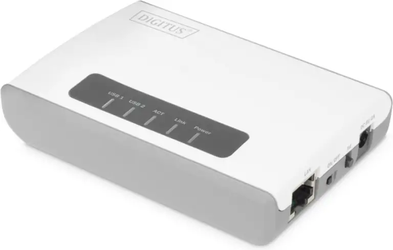
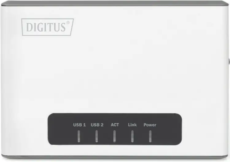
Power
This LED indicator is solid green when your router is powered on. Otherwise if this LED indicator is off, there is no power to your router.
Link
This LED indicators will be light on green while data is transmitted or received through your router LAN port. Be light on orange while unplugging the cable, the wireless connection successful.
ACT
This LED indicator is blinking green when the wireless is “On” and functioning properly with your . This LED indicator will be blinking green rapidly while data is transmitted or received by your wireless clients or wireless network devices connected to your router.
USB1/ USB2
This LED indicator will be blinking
Side view
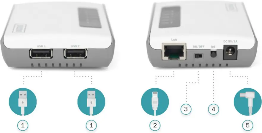
1) USB1 & USB2 Port
The USB 2.0 port allows you to connect USB printers and storage devices to your network and share access to these devices to computers on your network through the use of the included USB software utility.
2) LAN Port
This port allowes you to connect to the local network.
3) On/Off Power Switch
Move the On/Off switch to power “On” (Left position) or “Off” (Outer position) the device. (ON/OFF)
4) WPS/ Init Button
Push and hold this button for 5 seconds to activate Wi-Fi Protected Setup (WPS) Push Button Configuration (PBC) setup. Push and hold for 15 seconds to reset the device to its factory default setting.
5) Power Port
Connect the included power adapter from your router power port and to an available power outlet.
Application Diagram
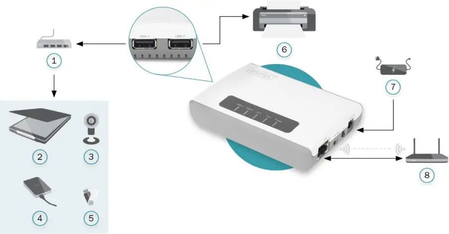
1 USB hub 5 USB stick
2 Scanner 6 Printer
3 IP camera 7 Power adapter
4 External HDD 8 Router
The device server allows you to share your regular printer or multi-function printer through a network. It is typically placed in the same location of your printer or multi-function printer. Unlike many print servers the 2-Port USB 2.0 Wireless Multi-Functional Network Server has the ability to communicate to your wireless network at data rates at Wireless N speeds eliminating any wires throughout your household or office. In addition to its print server functionality the wireless network server can also allow you to share USB storage devices over the network.
UTILITY INSTALLATION
Windows Installation
1) Install USB Device Server Control Center. It is available in the DN-13024 USB Device Server Product CD.
2) Click Install Utility
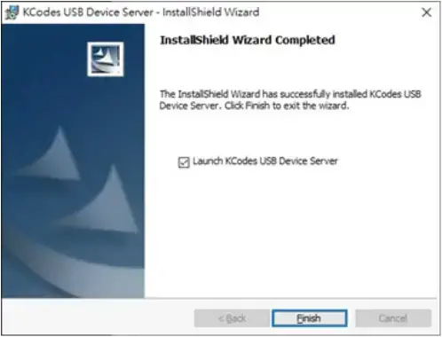
3) Follow the Install Shield Wizard instructions. Then click Finish.
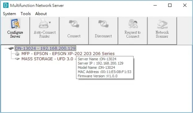
4) Start USB Device Server Control Center and Auto-searching USB device server window will appear.
5) The utility will automatically find the 2-Port USB 2.0 Wireless Multi-Functional Network Server and your printer. When the 2-Port USB 2.0 Wireless Multi-Functional Network Server is connected to your network.
CONNECTING THE DEVICE
1) Make sure that your USB devices are switched off and that the Server’s Power Adapter is disconnected.
2) Connect the Server to the network with a twisted-pair category 5 cable, 10baseT, 100baseTX and /1000Base-T RJ-45.
a) If you have a DHCP server on your network, your Server will receive an IP address automatically. The IP address will then appear on the Control Center or on the page of configuration report that you printed earlier. If your DHCP server does not give an IP address to the Server, the Server will use the automatic private IP addressing IP: 169.254.0.0. ~ 169.254.255.255
b) If you are not working in a DHCP network, you need to manually set the Server’s and PC IP address to IP: 169.254.0.0. ~ 169.254.255.255
IP Address
Unless you are assigning an IP address using DHCP, you must obtain an unused IP address from your network administrator
Methods for Setting the IP Address
1) You can set the IP address of your Server using one of the following methods, depending on your network operating environment:
a) Automatic IP Address Assignment
b) Manual IP Address Assignment
Connect the Power Adapter to the Server. The power indicator will light up and all light. indicators will flash in turn. After the boot is completed, the LINK & POWER light will be steady on and the ACT flashes.
Connect the USB devices to the USB1 and USB2 ports, turn on the USB devices and make sure it is ready for use, the USB1 and USB2 Link indicator lights up.
Setting the IP Address Using the Control Center
1) Double click the highlighted server (or click the “Configure Server” button) to get the server’s web pages. Click CONFIG icon.

2) Login with administrator ID (default: admin) and its password (default: admin). Methods for Setting the IP Address
Server Names and Server Name Rules
The default server name of the Server is “DN-13024”. If you put two or more Servers in your local area network, to avoid using the same server names you have to change the server names by using the Control Center or the Server’s web pages. If your server name is longer than 15 characters, the Server uses only the first 15 characters.
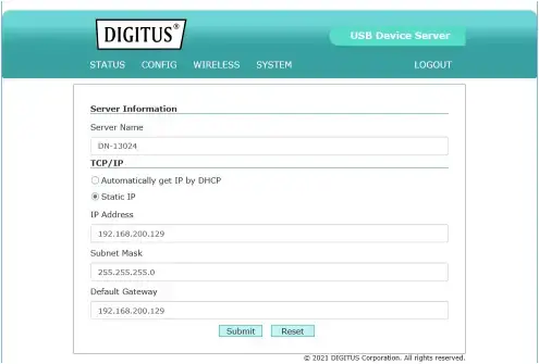
- Click the button corresponding to your choice of IP setting methods (static or dynamic using DHCP). When assigning a static IP address you also have to define Subnet Mask.
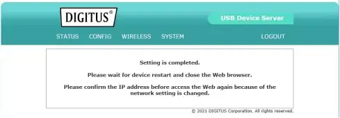
- Click Submit to save your settings. And the Server will reboot. You have now finished the procedure of setting the IP address
WIRELESS CONNECTION
Preliminary
- Before you can access the wireless networks, wireless parameters should be set correctly. You have to set up the first wireless parameter set through the LAN (wired) connection.
- Wireless access can be set as infrastructure (station) mode, which access needs point to route network messages with the same SSID.
- Wireless access can be secured by WEP (64/128), WPA-PSA (TKIP/AES), and WPA2PSK (AES).
- In infrastructure mode, if the network administrator wants to change any security related parameters, DN-13024 should be changed first, and then access point. If parameters mismatch causes wireless access is not allowed, you have to modify those parameters through LAN connection.
- In infrastructure mode, the maximal transfer rate is 150 MBits depending on the access point’s capability.
Set Wireless Configuration Using Control Center
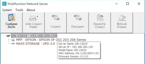
1) If the tool finds USB device servers in your local area network, then you have to select a server from the server list. Double click the highlighted server (or click the “Configure Server” button) to get the server’s web pages.
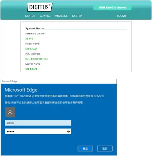
2) Click CONFIG icon. And Login with administrator ID (default: admin) and its password (default: admin).
Scan AP setting
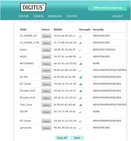
1) Click Wireless icon, click scan AP
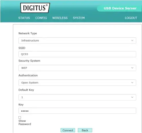
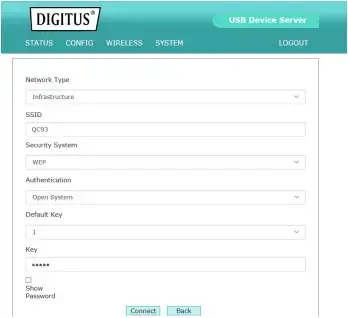
2) In order to join an existing wireless network, you have to set the correct SSID, and the correct security method with the correct key information. If the wireless network is secured by WEP64 or WEP128, key index and WEP key must be set correctly.
3) Type the Key then click Connect
4) If the wireless network is secured by WPA-PSK or WPA2-PSK, the key formats, shared key and encryption must be set correctly.
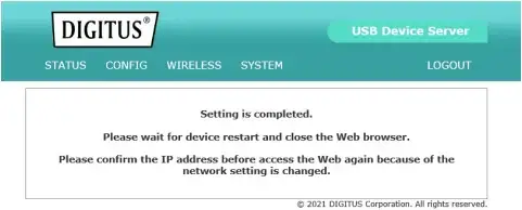
5) The Setting is completed then reboot the system
WPS Mode setting
Wi-Fi Protected Setup or WPS is a feature that allows the device to authenticate to your wireless network, the USB Device Server supports WPS Push Button and PIN Configuration. When using WPS make sure your wireless router or access point supports these features. The WPS Push Button Configuration or PBC can be initialized from a virtual button following the steps below or from a physical button located on the side of the unit. Please refer to Product Hardware Features section for more information.
There are 2 ways to install the USB Device Server. The easiest way is to use Wi-Fi Protected Setup (WPS) Push Button Configuration (PBC) setup. This feature allows you to setup your USB Device Server with your wireless network with just a push of a button. Wi-Fi Protected Setup (WPS) Push Button Configuration (PBC) Setup
Note:
- Make sure your wireless router or access point supports WPS (Wi-FI Protected Setup) PBC (Push button configuration).
- The USB Device Server must be placed in a location where it can still establish a wireless connection to your wireless network. The most ideal locations are areas where wireless adapters can maintain a 2-3 bars or 30-20% connection rating.
- Verify that any software that is required to operate your printer or multi-function printer is installed before installing the USB Device Server
- The utility must be installed on each computer in order to use your multi-function printer.
1) Place the print server in the desired location. The USB Device Server must be placed in a location where it can establish a wireless connection to your wireless network. The most ideal locations are areas where wireless adapters can maintain a 2-3 bars or 30-20% connection rating.
2) Plug in the power adapter and connect the print server. Move the power switch to the “On” position.
3) Connect your printer to the USB port on the print server.
4) Power on the printer.
5) Press and hold for 5 seconds the WPS button of your wireless router or access point.
Verify that the WPS feature is enabled and functioning. Please refer to your wireless router or access point’s manual or contact their technical support for instructions.
6) Press and hold for 5 seconds the WPS button on the USB Device Server. Wait 30 seconds while the print server synchronizes with your wireless router or access point.
7) Double click on the DIGITUS USB Control Center Utility icon.
8) The utility will automatically find the USB Device Server and the USB device you have connected to it.
Note: If the utility cannot find your USB Device Server, try to close and reopen the utility. If the utility still cannot locate your USB Device Server, it is likely the USB Device Server cannot establish a connection to your wireless network. Place the USB Device Server to a location where it can establish a wireless connection to your wireless network.
9) Select your printer and click Auto-Connect Printer. This will set your selected printer to connect to your computer for any print jobs.
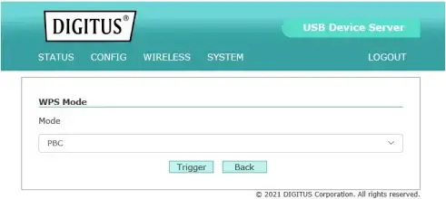
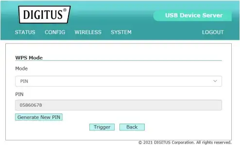
WPS Mode setting
1) Log into your router management page
(see “Access your router management page”)
2) Select the type of WPS Mode you would like to use.
a) PBC Mode: Select PBC
Click Trigger to initialize WPS
Initiate WPS Push Button on your wireless router or access point
b) PIN Mode: Select PIN
Click Trigger to initialize WPS
Enter the device’s PIN key on your wireless router or access point
USING THE USB DEVICE SERVER
Introduction
The goal of this produce is to provide the USB device server in a single product. We developed a new technology called “NetUSB” to achieve this goal. Basically, the “NetUSB” is a “USB over IP” technology that transparently redirects all USB packets to TCP/IP network channel. “NetUSB” allows you to use USB devices as if they were connected directly to your PC although they are actually remotely connected to the DN-13024 USB device server.
Connect & Disconnect
“NetUSB” allows you to use USB devices as if they were connected directly to your PC although they are actually remotely connected to the DN-13024 USB device server. The “connect” operation is a software operation that simulates an actual USB device plug-in. That is to say, when you do a “connect” operation in the Control Center, PC can then detect a USB device’s plug-in, although actually you do not plug in any USB device. Similarly, the “disconnect” operation is a software operation that simulates the disconnection of the USB device. Once the connect operation is successful, the operations to use that USB device are just the same as if the USB device is directly connected to the PC.
If a USB device is “connected” by a PC, we say that PC has the ownership of the USB device. Only one PC can get the ownership of a USB device at the same time. Therefore, if a USB device is connected by one PC, no other PC can connect this USB device until this USB device is disconnected.
Subnet Issue
Before using the NetUSB technology, you must first make sure that your PC can access USB device server via TCP/IP. The simplest way to do this is using “Control Center” to search for the USB device server on the network and change its IP address to be the same subnet as your PC. If the server and your PC are not in the same TCP/IP subnet, Control Center will show the server in red, as the following figure. You must change the IP address (or using DHCP) of the server so that the server and your PC are in the same subnet. Control Center will show these servers in blue, meaning you can access these servers by the NetUSB technology.
Installation of USB Device Driver
Some USB devices, like printers or MFPs (multifunction printers), require to install vendor-supplied driver (usually on CDROM). For those USB devices that do not need to install driver, please skip this section.
- Insert the CDROM into the CD drive and run the “autorun” program.
- Follow the instructions of the installation program to install driver.
- When the installation program asks you to plug-in the USB device, run the “Control Center”.
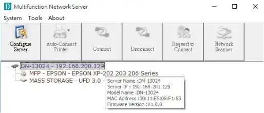
- In the Control Center, click the USB device server that has the desired USB device attached.
- Click the desired USB device as the following figure.
- Click the “Connect” button. Then the message “Manually Connect by your_computer_name” will be shown, as the following figure.
- Now, the installation program will detect the USB device and continue to install driver.
- After the installation is completed, click the USB device in the Control Center and then click the “Disconnect” button to disconnect the USB device.
Now the driver of your USB device is installed.
Using the USB Device Server
1) In the Control Center, click the USB device server that has the desired USB device attached.
2) Click the desired USB device.
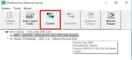
3) Click the “Connect” button. Then the message “Manually Connect by your_computer_name” will be shown.
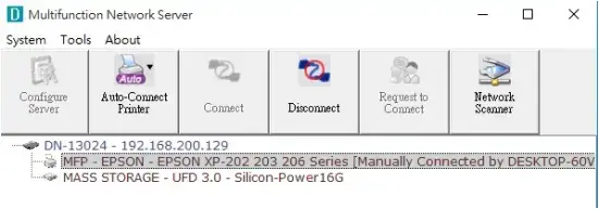
4) Now, PC will detect the plug-in of the USB device. The “connect” operation is a software operation that simulates an actual USB device plug-in. That is to say, when you do a “connect” operation in the Control Center, PC can then detect a USB device’s plug-in, although actually you do not plug in any USB device.
5) Then, just use the USB device as if it is connected directly to your PC’s USB port.
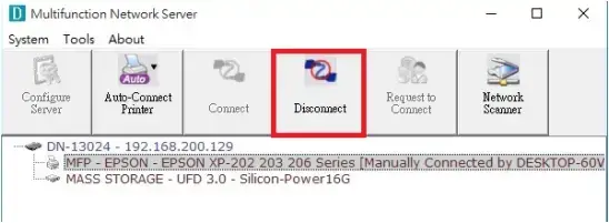
6) After you finish using the USB device, click the USB device in the Control Center and then click the “Disconnect” button to disconnect the USB device. Other PCs can not “Connect” the USB device until you “Disconnect” that USB device. That is to say, only one PC is allowed to connect the USB device at the same time.
Auto-Connect Printer
The method described in section 4.5 is so-called manual-connect, which means users must manually connect the USB device before using that device, and must manually disconnect the USB device after using the device, otherwise nobody else can connect this device. However, for printers and scanners (and MFPs), the USB device server supports auto-connect so users don’t need to manually connect/disconnect. This and the next sections show you how to do this.
After the driver is installed as described in section 4.4, you can see a newly created printer in the Control Panel’s “Printers and Faxes”. Follow the steps below to do a NetUSB auto-connect printing.
1) In the Control Center, click the USB device server that has the desired printer (or MFP) attached.
2) Click the desired printer (or MFP).
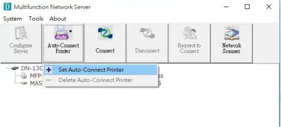
3) Click the “Auto Connect Printer” button and choose “Set Auto-Connect Printer”.
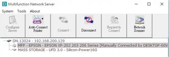
4) Choose the desired printer. The desired printer must be the Windows printer (this is a logical printer) that matches the printer attached on the USB device server (this is a physical printer). Then click the “Apply” button.
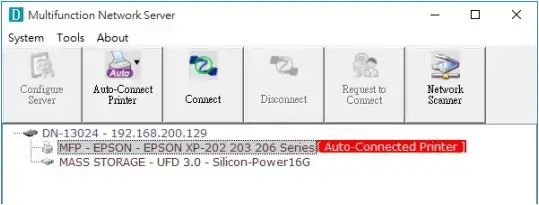
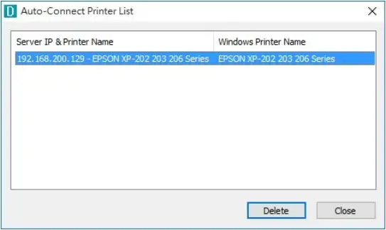
5) Then, the printer will be marked as an “Auto-Connected Printer” in red. If you choose “Auto-Connected Printer List” in the “Tools” menu, you can see a newly created item that describes the association between the Windows printer and the physical printer on the server.
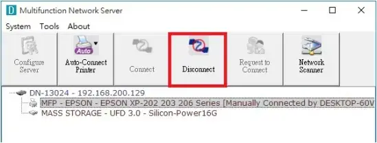
- Then try to issue a print job to the desired printer. You will see the Control Center will automatically do a connect operation. Then, the print job will be issued to that printer.
- Even you already properly setup an auto-connected printer, the Control Center must be running (in the background) while a print job is issued. This means you’d better run the Control Center every time after you login Windows. In order to skip this manual operation, you can make the Control Center be run automatically after you login Windows. To do this, choose the “Configuration” item in the “Tools” menu. The following window will appear. Click on the check box and then on the “OK” button. This feature is enabled by default.
If you would like to break the association between the Windows printer and the physical printer, just click on the association and click the “Delete” button in the “Auto-Connected Printer List”.
Network Scanner
For NetUSB scanning, we recommend you use Network Scanner as the following steps.
- In the Control Center, click the USB device server that has the desired MFP (or scanner) attached.
- Click the desired MFP (or scanner).
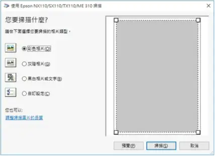
- Click the “Network Scanner” button. Then you can see that the Control Center will automatically do a “connect” operation. The following window will appear.
- Follow the usual steps to do scanning.
- After the scanning, close the “Auto-Connect Scanner” window. At this moment, Control Center will automatically do a disconnect.
USB Storage
You must use “manually connect” for USB storage. After you connect a USB storage, like the following picture, your PC will have a new disk. If the USB storage is a flash drive, the new disk is a “removable disk”.
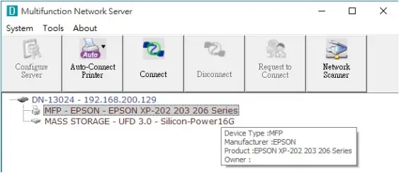
You can see the storage icon in the system tray.
Then just use the new disk as a general disk. After you finish the disk operations, click the storage icon in the system tray and choose “Safely remove USB Mass Storage Device” to remove the USB storage, as the following figure.
Then, in the Control Center, click the USB storage device and click the “Disconnect” button to disconnect the USB storage device.
Request to Connect
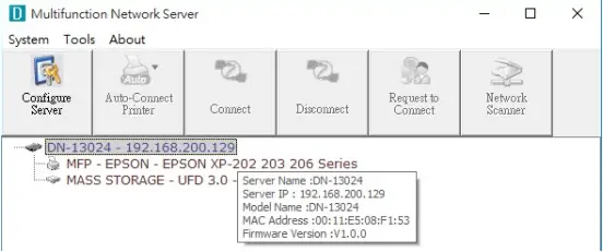
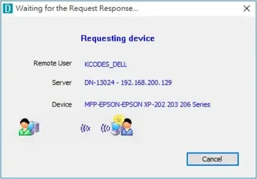
If a USB device is manually connected by any other user, basically you can not connect that device. However, we offer another mechanism called “Request to Connect” to solve this inconvenience. For example, there are two computers – TESTES and TEST. Now the owner of “HP Photosmart 2600” is TEST. Then, the TESTES computer wants to use this HP printer. The user on the TESTES computer can click the “Request to Connect” button in the Control Center. The following window appears.
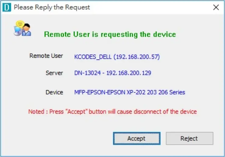
At this moment, the user on the TEST computer will see the following window, indicating that another computer – TESTES is requesting to use the HP printer.
The user will choose to accept or reject. If accepted, the Control Center on TEST will automatically disconnect the device and the Control Center on TESTES will automatically connect that device.
Quitting the Control Center
The Control Center doesn’t really quit if you click the “X” box (close box) at the top right corner of the window. Instead, it just minimizes itself to the system tray. There are two ways to really close the Control Center. The first way is choosing “Exit” item in the “File” menu in the Control Center. The second way is right-clicking the icon of the Control Center in the system tray and choosing the “Exit” item
Limitations
There are some limitations to use the NetUSB technology.
- Only supports Windows 7, 8, 10, 11, Mac OS X 10.7 Lion, Mac OS X 10.10 Yosemite, Mac OS X 10.11 El Capitan, Mac OS 10.12 Sierra, Mac OS 10.13 High Sierra, Mac OS 10.14 Mojave, Mac OS 10.15 Catalina
- Only one PC can get the ownership of the same USB device at the same time.
RESTORE FACTORY DEFAULTS
You may restore the Server’s default parameters by one of the following methods.
Using the Server’s Web Pages
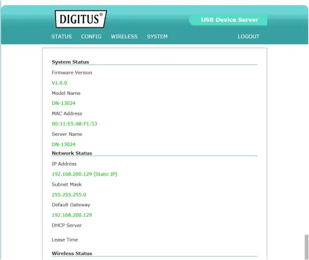
Click on the “STATUS” icon to see system status, network status and Wireless Status
1) Go to the Server’s web page and click SYSTEM
2) Enter administrator (default: admin) and password (default: admin).
3) Click Factory Default.
4) Click Yes to confirm
UPGRADE FIRMWARE
This chapter describes how to upgrade firmware. Please follow the following Procedures:
Using the Control Center
1) Open Control Center. It will automatically search the existing Servers and display their statuses.
2) Select the Server that you want to upgrade the firmware. Double click the selected Server to get the serve’s main web page.
3) Click CONFIG icon.
4) Login the Server with Administrator (default: admin) and Password (default: admin).
5) Click Upgrade Firmware.
6) Click Browse button to choose the file of new firmware.
7) Click Upload button to start firmware upgrade.
8) Wait for 35 seconds for system reboot.
Using Init /WPS Button
1) Turn on server and wait until you can see it on control center, press the initial button over 10 sec. Server will automatically shut down and restart, this process will take about 1 min, after restart server will back to factory default.
2) Wi-Fi Protected Setup (WPS) streamlines the process of connecting to a wireless network. This compact device fits into the smallest spaces. Activates WPS Function (press for 2~5 seconds)
Default Parameters List
General Information
- Server Name: DN-1302
TCP/IP
- Automatically get IP by DHCP: Enabled
- Static IP: Disabled
- IP Address: 192.168.1.100
- Subnet Mask: 255.255.255.0
User Accounts
- Administrator: admin
- Password: admin
THE SERVER’S WEB PAGES
Introduction
The Server runs the http server, http on TCP port: 80. Users may use the web pages to see the Server’s system status and configure the Server.
Management Page Structure
1) STATUS
System Status
- Firmware Version
- Model Name
- MAC Address
- Server Name
Network Status
- IP Address
- Subnet Mask
- Default Gateway
- DHCP Server
- Lease Time
Wireless Status
- SSID
- BSSID
- Channel No
- Network Type
- Signal Strength
- Link Quality
- Security System
2) CONFIG
Server Information
- Server Name
TCP/IP
- Automatically get IP by DHCP
- Static IP
- IP Address
- Subnet Mask
- Default Gateway
3) WIRELESS
- Connect To AP
- Scan AP
- Manual Connect
- WPS Setting
4) SYSTEM
- Set Administrator
- Administrator
- New Password
- Re-type Password
- Maintenance
- Restart
- Factory Default
- Firmware Upgrade
Technical Description
- Frequency Range: 2412MHz-2472MHz (13/9 channels)
- Transmit Power: <20 dBm EIRP
- Hardware Version: 1.0
- Software Version: 0.08
Hereby Assmann Electronic GmbH, declares that the Declaration of Conformity is part of the shipping content. If the Declaration of Conformity is missing, you can request it by post under the below mentioned manufacturer address.
www.assmann.com
Assmann Electronic GmbH
Auf dem Schüffel 3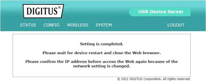
58513 Lüdenscheid
Germany