DMP Network Zone Expander Module Installation Guide
ABOUT THE 714N-POE
The 714N-POE Network Zone Expander Module allow you to add 4 zones to XR150/XR550 Series panels using IP network capability. The 714N-POE is compatible with 1k to 10k resistors, giving a wide variety of options for takeovers.
Power Supply
714N-POE module operates at 12 VDC from a power supply. The 714N-POE can also be powered from POE.
Zone Terminals
Four input zones are provided to allow connection of nearby burglary devices.
Programming Connection
The module also provides a keypad programming connection for use with a standard DMP LCD keypad for initial setup. Programming can be completed using a keypad connected to the module or from XR150/XR550 panels.
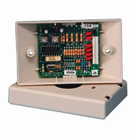
PCB FEATURES
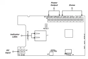
Figure 1: PCB Features
INSTALL THE 714N-POE
1.Mount the Module
The module comes in a high‑impact plastic housing that you can mount directly to a wall, backboard, or other flat surface.
For easy installation, the back and ends of the 734 housing have wire entrances. The back also contains multiple mounting holes that allow you to mount the module on a single‑gang switch box. DMP recommends mounting the 734 near the protected door. Refer to Figure 2 for mounting hole locations on the housing base.
- Remove the PCB from the plastic housing by loosening the clips on one side and gently lifting it out of the housing base.
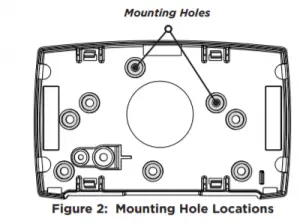
- Insert the included screws in the desired mounting hole locations and tighten them to secure the housing to the surface.
- Reinstall the PCB in the housing base.
2. Wire the Zone Terminals
Terminals 5-9 connect grounded zones 1 through 3. Zone 4 terminals provide a non-powered Class B, Style A zone. The valid range of EOL resistors is 1k to 10k, allowing for a wider range of takeovers. Refer to the panel programming guide for programming instructions. See Figure 3 for more information on wiring the zone terminals.
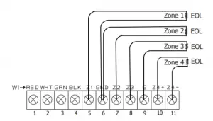
Figure 3: Zone Terminal Wiring
3. Network Connection
Connect an IP network cable from the LAN/WAN connection to the 714N-POE Network connector. The 714N-POE module communicates AES encrypted TCP with panels that have network installed.
Two LEDs are located on the Ethernet jack. The green LED indicates data sent to the panel.
The yellow LED indicates the speed of the transmission. A solid yellow LED indicates the network is connected at 100 Base-T. A flashing yellow LED indicates the network is connected at 10 Base-T.
4. Set the Module AddressNote
For XR Series Version 192 firmware and lower, the 714N-POE must be programmed as a network door. In Version 193 firmware and higher, the 714N-POE should be programmed as a network expander. Refer to the XR Series panel programming guide (LT-1232) as needed.
Keypad Bus Addresses
DMP XR150/XR550 Series panels use keypad bus addresses 1 through 16. Each keypad bus address can accommodate one 714N-POE. A module with an address of 2 on the keypad bus would represent Door 2 and zones 21-24. A module with a keypad address of 14 would represent Door 14 and zones 141-144.
AX-Bus Addresses (XR550 only)
DMP XR550 panels are capable of access control expansion using any of the five AX/LX-Bus headers (AX/LX500, 600, 700, 800, and 900). The 714N-POE takes up an AX-Bus address that can no longer be used for a door. The 714N-POE module shares AX-bus addresses with the 734N, which limits the number of devices to 16. A module with an address of 501 on AX500 would represent zones 501-504. A module with an address of 505 on AX500 would represent zones 505-508. A module with an address of 701 on AX700 would represent zones 701-704.
Setting the 714N-POE Addresses
Only valid zone numbers can be assigned 714N-POE in device setup. For complete keypad and AX-Bus address mapping, see the chart below.
| KEYPAD BUS | AX-BUS | ||||||||||
| DEVICE/ DOOR | ZONES | DEVICE/ DOOR | ZONES | DEVICE/ DOOR | ZONES | DEVICE/ DOOR | ZONES | DEVICE/ DOOR | ZONES | DEVICE/ DOOR | ZONES |
| 1 | 11‑14 | 501 | 501‑504 | 601 | 601‑604 | 701 | 701‑704 | 801 | 801‑804 | 901 | 901‑904 |
| 2 | 21‑24 | 505 | 505‑508 | 605 | 605‑608 | 705 | 705‑708 | 805 | 805‑808 | 905 | 905‑908 |
| 3 | 31‑34 | 509 | 509‑512 | 609 | 609‑612 | 709 | 709‑712 | 809 | 809‑812 | 909 | 909‑912 |
| 4 | 41‑44 | 513 | 513‑516 | 613 | 613‑616 | 713 | 713‑716 | 813 | 813‑816 | 913 | 913‑916 |
| 5 | 51‑54 | 517 | 517‑520 | 617 | 617‑620 | 717 | 717‑720 | 817 | 817‑820 | 917 | 917‑920 |
| 6 | 61‑64 | 521 | 521‑524 | 621 | 621‑624 | 721 | 721‑724 | 821 | 821‑824 | 921 | 921‑924 |
| 7 | 71‑74 | 525 | 525‑528 | 625 | 625‑628 | 725 | 725‑728 | 825 | 825‑828 | 925 | 925‑928 |
| 8 | 81‑84 | 529 | 529‑532 | 629 | 629‑632 | 729 | 729‑732 | 829 | 829‑832 | 929 | 929‑932 |
| 9 | 91‑94 | 533 | 533‑536 | 633 | 633‑636 | 733 | 733‑736 | 833 | 833‑836 | 933 | 933‑936 |
| 10 | 101‑104 | 537 | 537‑540 | 637 | 637‑640 | 737 | 737‑740 | 837 | 837‑840 | 937 | 937‑940 |
| 11 | 111‑114 | 541 | 541‑544 | 641 | 641‑644 | 741 | 741‑744 | 841 | 841‑844 | 941 | 941‑944 |
| 12 | 121‑124 | 545 | 545‑548 | 645 | 645‑648 | 745 | 745‑748 | 845 | 845‑848 | 945 | 945‑948 |
| 13 | 131‑134 | 549 | 549‑552 | 649 | 649‑652 | 749 | 749‑752 | 849 | 849‑852 | 949 | 949‑952 |
| 14 | 141‑144 | 553 | 553‑556 | 653 | 653‑656 | 753 | 753‑756 | 853 | 853‑856 | 953 | 953‑956 |
| 15 | 151‑154 | 557 | 557‑560 | 657 | 657‑660 | 757 | 757‑760 | 857 | 857‑860 | 957 | 957‑960 |
| 16 | 161‑164 | 561 | 561‑564 | 661 | 661‑664 | 761 | 761‑764 | 861 | 861‑864 | 961 | 961‑964 |
Table 1: Device Addresses and Zone Numbers
PROGRAM THE MODULE
When you program the 714N-POE module, you must use a keypad connected to the programming header and set to address 1.
You can also program the module from an XR150/XR550 Series panel. Initial programming of device and communication must be performed with a keypad. Afterwards, device programming and 714N-POE options may be programmed from the panel’s programming interface. The panel’s programming overrides any programming performed from a keypad connected to the module.
Reset Header
To reset the module when first installing the system, short the two pins on the reset header before applying power to the module.
To reset the module while the system is operational, short the two pins on the reset header for one or two seconds without powering down the system.
Program Start Display
When you connect the keypad to the module, the version number and release date display. Press 6653 (PROG) then CMD to enter the Programming Menu.
Initialization Option
These options can set the 714N-POE module programming memory back to factory defaults. Press any select key or area to enter the initialization menu.
Initialize Confirm Option
The module displays SURE? YES NO for confirmation to clear the memory. This is a safeguard against accidentally erasing the programming. No memory is cleared from the programming until you answer YES to the SURE? option. Selecting NO leaves communication options unchanged.
Communication Menu
Press any select key or area to enter the Communication menu. Select NET as the communication type.
714N DHCP
Select YES to use dynamic IP address information for the module’s IP Address, Subnet Mask, and Gateway Address. Select NO to enter static IP information.
714N IP Address
Enter the static IP address of the module if the DHCP is set to NO. Default is 192.168.0.201.
Subnet Mask
Enter the local subnet mask assigned to the module. Default is 255.255.255.0.
Gateway Address
Enter the local gateway address of the module. Default is 192.168.0.1
Panel IP Address
Enter the IP address of the panel. Default is 192.168.0.1.
Note: This IP address must match the address programmed in the panel at the Local IP Address option in Network Options. The DHCP programming in the panel must be set to NO.
Panel IP Port
Enter the port number that the module uses to send communication to the panel. This must be the same port that is programmed in the 714N-POE Listen Port in Network Options programming of the panel. The panel IP port cannot be the same as the panel network programming port. Default is 2002.
714N-POE Passphrase
You must enter an 8-16 character alphanumeric passphrase to encrypt communication with the panel. The passphrase for the 714N-POE must match the 734N passphrase entered in Network Options programming of the panel. If no 734N has been installed, a passphrase is still required for the 714N-POE to communicate with the panel. The passphrase is blank by default.
714N-POE NETWORK SPECIFICATIONS
The 714N-POE was designed to have minimum impact on network performance.
If required, all of the traffic between the module panel can be completely isolated from the rest of the existing network by connecting all of the 714N-POE modules and the panel to the same switch, then connecting the switch to the remainder of the network. As a result, all traffic between the modules and the panel is confined to the switch they are connected to, while still allowing the panel to communicate with the central station through the normal network.
The 714N-POE is a single. purpose network device. The module establishes outbound panel communication using the TCP/IP protocol that remains open indefinitely. No inbound communication is allowed. This prevents attackers from making any type of connection with the modules through the network.
All communication between the 714N-POE and the control panel is encrypted using 128-bit AES encryption. This is the same encryption standard approved and used by the U.S. government, including the National Security Agency for encrypting secret information.
The socket can be closed by the 714N-POE or panel after a time-out. The connection is re-established by the 714N-POE after the time-out.
A pair of supervision packets are sent every 5 seconds:
- The payload for each packet is 18 bytes and the total traffic, including overhead, is approximately 2 kB per minute for each 714N-POE.
- Non-Supervision messages have a payload range of 18-50 bytes.
714N-POE encryption has not been evaluated by UL.
COMPLIANCE LISTING SPECIFICATIONS
Commercial Burglary (XR550 Series Panels)
When using the zones of the 714N-POE in a listed application, place the module in a listed enclosure and connect a DMP Model 307 Clip-on Tamper Switch to the enclosure programmed as a 24-Hour zone. The 714N-POE zones can be used in a Low Risk application
PRODUCT SPECIFICATIONS
Primary Power 8.5 VDC to 28.5 VDC if 12 VDC
Current Draw
Standby/Alarm 75 mA at 12 VDC
When powered from POE
Standby/Alarm 25 mA
Output Voltage (POE) 12 VDC
Maximum Power Draw (POE) 12.95 W
Available Output Current 750 mA
Zones 5 VDC, 2 mA max
Dimensions 4.5 W x 2.75 H x 1.75 D in
11.43 W x 7 H x 4.45 D cm
Weight 8 oz (0.23 kg)
CERTIFICATIONS
FCC Part 15
Underwriters Laboratory (UL Listed)
ANSI/UL 294 Access Control System Units
ANSI/UL 609 Local Burglar Alarm Units And Systems
ANSI/UL 1076 Proprietary Burglar Alarm Units And Systems
ANSI/UL 1610 Central Station Burglar-Alarm Units
FCC INFORMATION
This device complies with Part 15 of the FCC Rules. Operation is subject to the following two conditions:
- This device may not cause harmful interference, and
- This device must accept any interference received, including interference that may cause undesired operation.
Changes or modifications made by the user and not expressly approved by the party responsible for compliance could void the user’s authority to operate the equipment.
Note: This equipment has been tested and found to comply with the limits for a Class B digital device, pursuant to part 15 of the FCC Rules. These limits are designed to provide reasonable protection against harmful interference in a residential installation. This equipment generates, uses and can radiate radio frequency energy and, if not installed and used in accordance with the instructions, may cause harmful interference to radio communications. However, there is no guarantee that interference will not occur in a particular installation. If this equipment does cause harmful interference to radio or television reception, which can be determined by turning the equipment off and on, the user is encouraged to try to correct the interference by one or more of the following measures:
- Reorient or relocate the receiving antenna.
- Increase the separation between the equipment and receiver.
- Connect the equipment into an outlet on a circuit different from that to which the receiver is connected.
- Consult the dealer or an experienced radio/TV technician for help.
Information furnished is believed to be accurate and reliable.
This information is subject to change without notice.