HD Digital Wireless Backup Camera &Monitor
Kit Product Manual/Installation Instructions

Please read this manual thoroughly before operating the device, and keep it for future reference.
Customer Service Team Email: [email protected]
As a brand manufacturer, we offer a two-year warranty, 30-day money-back guarantee, and 24-hour online service. If you have any product questions, please contact us.
Certificate
This system has been certified by the following authorities and is safe to use: CE & FCC & & EMC & RoHs & Waterproof.

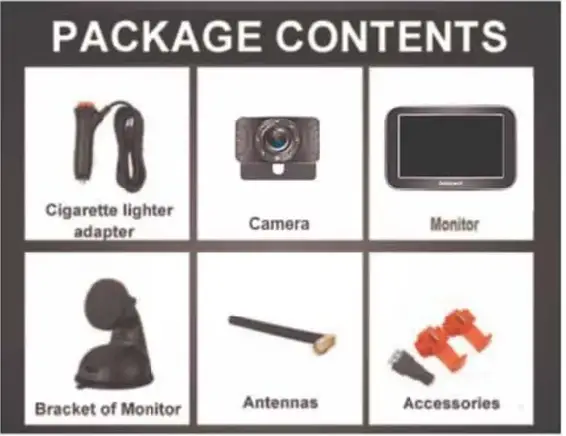
Package includes
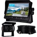
- 1* Digital Wireless License plate camera
- 1* Digital Wireless Mon tor
- 2* Power Cords
- 1* Windshield Mount Bracket
- 1* Cigarette lighter adapter
- 1* Taps
- 1* Split connector adapter
- 1* Antenna
- 1* Instruction manual

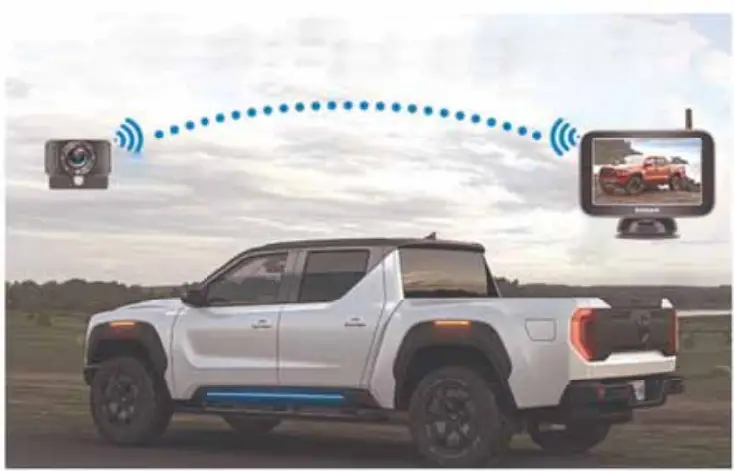
Application
The system is compatible with Cars, Pickups, Smaller RVs, Campers,Trucks (with 9v – 24v power)
If you meet any signal issue, like flickers with the image, just contact us for tech support or we can send an upgrade kit that has a stronger signal for replacement.
Working Voltage
Please note below the data of power supply input to the monitor and camera.
Note: If the power is over 2’V to the camera, it will cause the camera damaged.
Monitor: voltage range:11V-36V
Camera and Transmitter: 11V-24V
Installation video
Please watch the below video on YouTube to help you install the system. https://youtube//M7YD kJ-11 From
Note: If you are unable to open the video, there may be a typing software error.
You have two ways to access the videos:
- Search the video id M7YDkJH1FoM on www.youtube.com
- Contact the after-sales service team [email protected] to get the links.
Testing before Installation
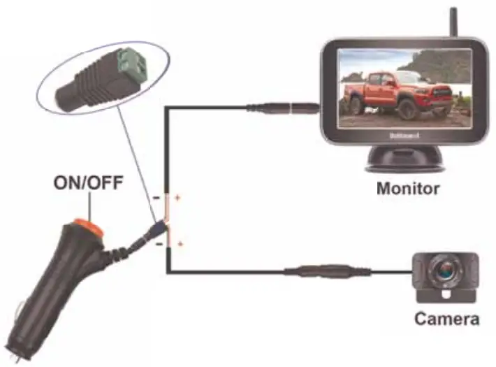
After you receive the system, please test the device before installation. Please reference the way below the Image shown.
- Plug power cords to the monitor and merged the power wires to the camera,red-red, black-black.
- Loose the screws on the green adapter, then insert the red wire(copper wire) into the Positive(+) slot, and the black wire(copper wire) into the Negative(-)
- Plug into the cigarette lighter and turn on the red switch. If you see an image on a monitor, it means the system works well.
After testing, you need to make sure that the image appears on the screen, then you can install it on your vehicle.
Wires connection
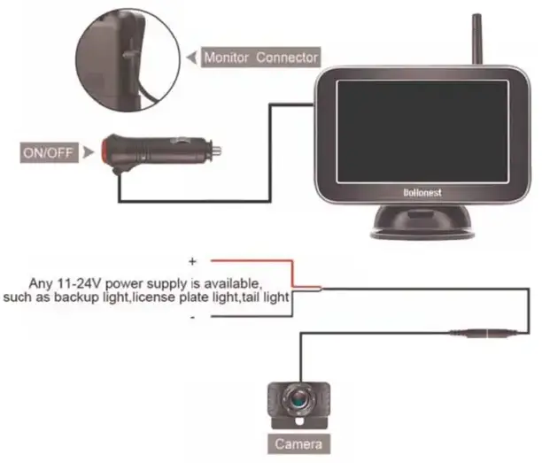
- The monitor can be powered by a cigarette lighter.
- If you just need the system used for backup, please connect the camera to the backup light/reverse light. The red wire on the camera is connected to the positive pole of the vehicle light wire, and the black wire is connected to the negative pole of the vehicle light wire.
- If you want the system to work for continuous use, please connect the camera to the tail light/running light / License plate light which is continuous on.
Warning:
- The working voltage range of the camera is 11V-24V, but we recommend the customer to use it on 12V because the power supply voltage of most vehicles is 12V. If the power supply voltage of the camera woe eds 24V for a long time or exceeds 40V for a short time, it will cause the camera’s extension wire to be smoking and damaged wires that caused the system doesn’t work, but will not be caught fire. There is no safety issue.
- Please pay attention to the positive and negative poles of the wire. If the positive and negative poles are reversed, it may cause the no images please correct the positive wire and negative wire asap. Please don’t judge the positive wire or negative wire with the color of the wires, You should search it on the Internet or ask the professional Jerson or use the tools to confirm it.
- If the no images issue is caused by the touch connections of the T-Taps, please check and remove the T-Taps to hardwire them to the car light wire.
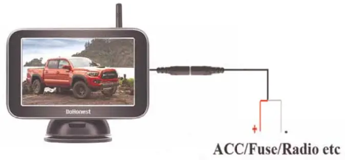
- There is a power cord that can be powered supply to the monitor from ACC/Fuse/Radio etc. The red wire connects to the Positive, while the black wire to the Ground or Negative.
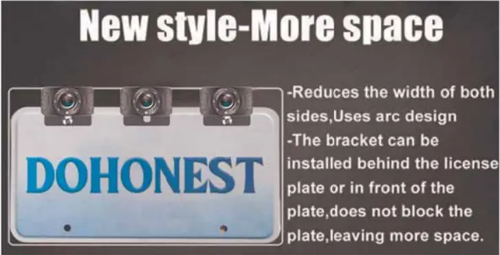
Installation of camera
(Mlle camera needs to be attached to the license plate, and the power cord needs to be connected to the reversing light or taillight. The red wire is connected to the Positive, and the black wire to the Negative or Ground the sum Lul al mot Vu time w. ).
The minimum rein hides. then holder in the hock of the heaven plot shown below:
We have prepared
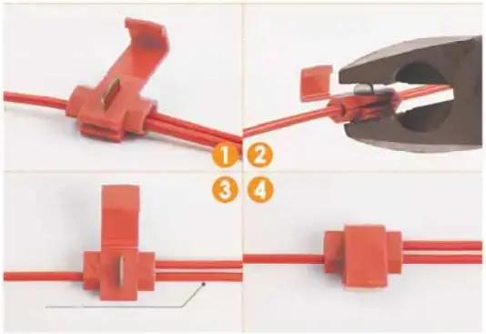
A T-Tap adapter to better protect the cord of the reversing backup light and tail light, please reference the picture below, which makes the installation easier.
Step l-step4:
Slept1: Plug the power cord of the reversing lump into the first hole of the clamp.
Step2: Put the backing auxiliary wire into the second hole of the clamp (the hole is blocked to prevent leakage)
Step3: Clamp the adapter, and clamp the iron sheet to the bottom.
Step4: The step is finished.
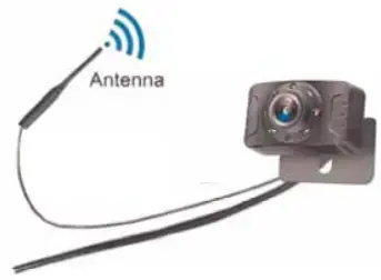
The antenna for the license plate backup camera is Waterproof.
There is o thin we with time from the contra (see below sample image
The antenna is waterproof, you can put the antenna outdoor inside the AUTO., it will not affect by the water or rain.
Please fix it in a proper position MO make the transmission of the signal powerful if the vehicle n kayo, pleased; nukeIns or donna on the pedal position.
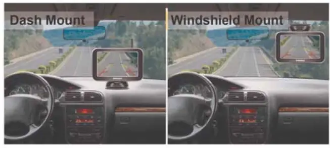
Monitor Installation
The monitor is attached to the WlikthshMld or Dashboard.
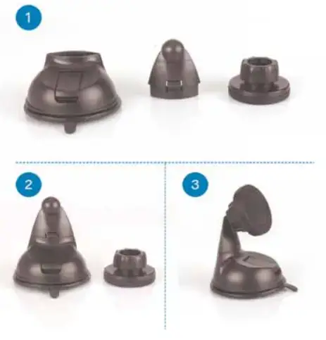
(i) First assemble the parts of the bracket together
(ii) Stick a round piece of iron behind the menace
(iii): Stick the bracket to the back of the: genitor with the suction of the magnet
(iv): Mount on dosh ce windshield which is up to you.
Note: The monitor screen has a protective film. If you don’t want It, you can tear off the protective film. Or you can keep it without tearing.
Monitor-Button
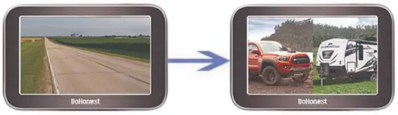
- Up (+): Press to increase and press it can switch channels quickly.
Single/Split Screen: The default is CAM1. Press the + key once to switch to CAM2, and press The + key twice to switch to the split-screen.
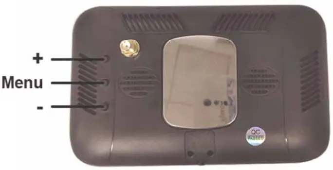
- Menu : Press this to enter the menu mode( To enter the menu page, you must switch to a single screen)
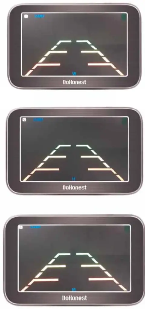
- Down (-): Press to reduce, turn on/off guidelines, and DIY guide
You can adjust the height and width of the guideline, and move the guideline left and right
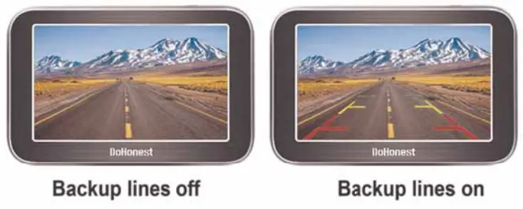
Guide Lines ON/OFF:
The default guide line is on. Click the – key four times to turn it off.
BACKUP LINES OPTION
Product function introduction
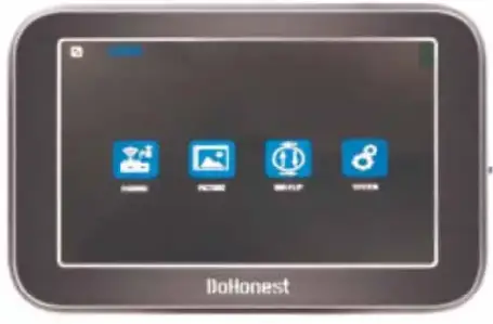
When you press the Menu button, you will enter the Menu mode and see 4 icons with functions:
 Note:
Note:
- Press the + or – key can switch the function icon.
- Press the Menu key to enter or confirm the change.
- first icon Pairing:
Step 1: Make sure the camera and monitor are powered .
Step 2: When you choose Pairing, the icon is yellow, press the M button to enter pairing mode. The icon “Pairing Start” appears, Then Wait for the image to appear. (About 20 seconds)
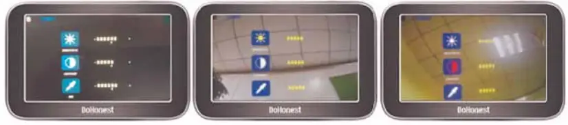
- Second icon “Picture”
For setting brightness, contrast, and saturation
When you choose the 2nd icon “Picture” which became yellow, Press the “M” button, and you can see the brightness, contrast, and saturation icon. and press the + or – button to choose the icon you want to adjust and press “M” to choose it. When the selected icon turns red, you can press + or – adjust the data.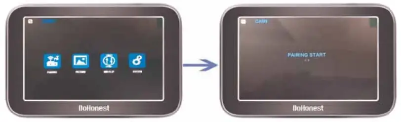
- Third icon MIR-Flip:
When you choose the 3rd icon MIR-Flip became yellow, Press the “M” button to enter it. Then you can press + or – switch from mirror Rear View image, Normal front view image, vertical flip image. (4 options).
- Setting:
Note: When you press the M key to enter this mode, Just press + or – to switch the different functions icons. Then press the M key again to select it (became red icon), then you can press + and – to adjust the data. After you did, press the M key to quit the current mode.
Switch Language
I. DELAY TIME ( This function is useless )
II. SCAN TIME (Set time for scan time for each camera channel)
III. Automatic channel switching ON/OFF (If this function is ON, the CAM1 and CAM2 will switchable automatically, SCAN TIME will be set for scan time for each camera. You can set it for OFF ignore these functions).
![]()
Note: When the yellow font *scan’ appears on the screen, it means that the function already exists, and CAM1 and CAM2 will automatically switch.
The function of the Camera Extension Wire
- The White Wire.
The camera comes with 7 LED lights that will automatically light on at dark to enhance the night vision, if you do this it is dazzling. You can cut the thin white wire from the extension of the camera, then the 7 LED lights will turn off.
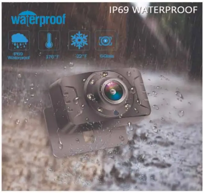
IP69K Waterproof

Troubleshooting
- After installation, you turn on the monitor and camera power without images, at the same time, the monitor turns on for five seconds and then goes black, which means something wrong with the camera. You need to check that the camera is plugged incorrectly. If the camera’s power cord is not connected correctly to the headlights, there are no images. Or you can touch the camera with your hand if the camera gets hot, ifs powered on; if the camera surface temperature does not change, it is not connected to the power. Then, you need to reconnect to the power.
- If the positive and negative poles are reversed, it may cause the no images, and please correct the positive wire and negative wire asap. Please don’t judge the positive wire or negative wire with the color of the wires, You should search it on the Internet or ask a professional person or use the tools to confirm it. If the no images issue is caused by the touch connections of the T-Taps, please check and remove the T-Taps to hardwire them to the car light wire.
- If you find the image flashing all the time after you install this system. Please try to turn off the engine and keep the key in ACC, if the image does not flicker and the image starts to flicker after starting the engine, you need to add a 12V DC Power Adapter Filter Rectifier to keep the signal stable. ( VW, Dodge, Audi, BMW, and Mercedes cars will repel foreign devices and emit interfering currents. )
- If you connect the camera to the headlights, and your headlights are LED, it will not work. Because the LED light cannot provide a constant direct current to the camera, you need to connect another power source to power the camera.
Two Years Quality Warranty
Two years quality warranty and lifetime tech support. Please contact us if you meet any issues.
No matter what problems you have, please contact us and you will get professional help.
Email address: [email protected]
Thank you!
FCC Warning Statement
Changes or modifications not expressly approved by the party responsible for compliance could void the user’s authority to operate the equipment. This equipment has been tested and found to comply with the limits for a Class B digital device, pursuant to Part 15 of the FCC Rules. These limits are designed to provide reasonable protection against harmful interference in a residential installation. This equipment generates uses and can radiate radio frequency energy and, if not installed and used in accordance with the instructions, may cause harmful interference to radio communications. However, there is no guarantee that interference will not occur in a particular installation. If this equipment does cause harmful interference to radio or television reception, which can be determined by turning the equipment off and on, the user is encouraged to try to correct the interference by one or more of the following measures:
‐‐ Reorient or relocate the receiving antenna.
‐‐ Increase the separation between the equipment and receiver.
‐‐Connect the equipment into an outlet on a circuit different from that to which the receiver is connected.
‐‐ Consult the dealer or an experienced radio/TV technician for help.
This device complies with part 15 of the FCC Rules. Operation is subject to the following two conditions: (1) This device may not cause harmful interference, and (2) this device must accept any interference received, including interference that may cause undesired operation.
RF Exposure Statement
To maintain compliance with FCC’s RF exposure guidelines, This equipment should be installed and operated with a minimum distance of 20cm from the radiator of your body. This device and its antenna(s) must not be co-located or operated in conjunction with any other antenna or transmitter.