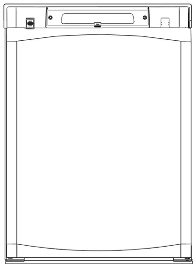
DOMETIC RM2350 3 Way Fridge and Freezer 90L
INSTALLATION INSTRUCTIONS
GENERAL INFORMATION
The installation, servicing and gas installation must be performed by an authorised/qualified person. The refrigerator must be installed in accordance with the manufacturers installation instructions, local gas fitting regulations, municipal building codes, electrical wiring regulations, AS5601.2 “Gas Installations” and any other statutory regulations.
PACKAGING
The packaging of this appliance is design to withstand the transportation from the factory to the point where it will be installed in the recreational vehicle.
Before starting to install the appliance, please, make sure all parts of the packaging have been removed, so there will not be anything left that may come into contact with heat parts of the appliance or obstruct the combustion exhaust gases or the air movement around the cooling unit.
VENTILATION REQUIREMENTS
The installation shall be made in such a manner as to separate the combustion system from the living space of the mobile home or recreational vehicle. Proper installation requires one lower fresh air intake and one upper exhaust vent.
We recommend fitting the Dometic ventilation system, which is specially developed by Dometic for this purpose. The ventilation kits must be installed and used without modification.
An opening toward the outside at floor level in the refrigerator compartment must be provided for ventilation of heavierthan-air fuel gases. The lower vent of the recommended kits is provided with proper size openings. The flow of combustion and ventilating air must not be obstructed.
The lower side vent provides an adequate access opening for ready serviceability of the burner and control manifold of the refrigerator. This should be centred on the back of the refrigerator.
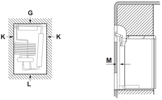
CLEARANCES
| MINIMUM CLEARANCES TO COMBUSTIBLE MATERIAL | |||
| inch | mm | ||
| Top | G | 0 | 0 |
| Side | K | 0 | 0 |
| Bottom | L | 0 | 0 |
| Rear | M | 1 | 25 |
If the lower grille is not at floor level where leaking gas can escape, a 40 mm hole to the outside should be made in the floor of the recess to drain any unburned gas to the outside. Fit the hole with wire mesh and an angled plate to protect it from stones, mud etc.
MINIMUM VENTILATION REQUIREMENTS
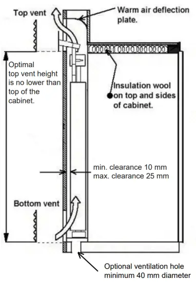
Notice: If the design of the vehicle does not allow you to install the top exhaust vent directly above the condenser of the refrigerator (what Dometic recommends):
“Minimum top vent height is 746 mm (top of upper vent opening)”
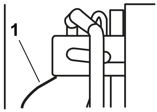
To compensate for the lowered vent it is required that the deflector plate (1) is installed so that it touches the leading bottom edge of the condenser unit.
Ventilation System (Not Included)
Ventilation components are:
– 1x AS1625 vent kit (top & bottom vents with frames)
– 1x TP (includes 1x tee piece & 1x extension)
– Extra extensions may be required depending on the height of refrigerator and vent height.
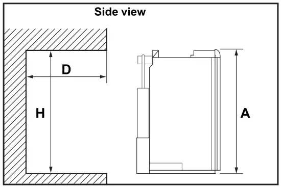
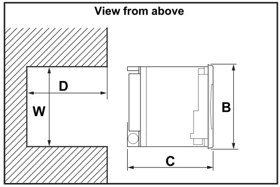
DIMENSIONS
The following dimensions offer adequate space for service and proper installation.
| OVERALL DIMENSIONS | RECESS DIMENSIONS | |||||
| Height
A |
Width
B |
Depth
C |
Height
H |
Width
W |
Depth
D |
|
| inch | 30-5/32 | 21-7/8 | 22-23/32 | 29-3/4 | 20-1/2 | 21-3/8 |
| mm | 766 | 556 | 577 | 756 | 521 | 542 |
INSTALLING THE REFRIGERATOR
- It is essential that all maximum or minimum dimensions are strictly maintained, as the performance of the refrigerator is dependent on adequate flow of air over the rear of the refrigerator. The refrigerator must be installed in a substantial enclosure and must be level, see “DIMENSIONS”.
- Note! Do not install the appliance directly on carpeting. Carpeting must be removed or protected by a metal or wood panel beneath the appliance, which extends at least full width and depth of the appliance.
- The space between the storage cabinet and the top of the refrigerator should be blocked otherwise heat will become trapped in this space, making the top of the refrigerator hot, thus reducing the efficiency of the unit. All areas within the recess in which the refrigerator is installed must be sealed: – Make sure that there is a complete seal between the front frame of the refrigerator and the top, sides and bottom of the enclosure. A length of sealing strip is applied to the rear surface of the front frame for this purpose.
– Apply a sealing strip to the foremost floor of the enclosure. The sealing should provide a complete isolation of theappliance’s combustion system from the vehicle interior.
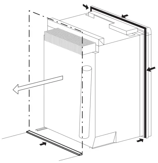
Note! Be careful not to damage the sealing strip when the refrigerator is put in place.
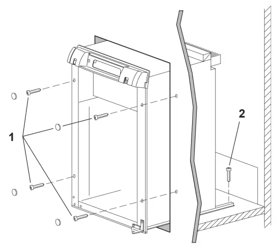
SECURING THE REFRIGERATOR
Failure to follow the sequence in securing refrigerator in enclosure can cause leakage between the frame and cabinet! After the refrigerator is put in place, (insuring a combustion seal at the front frame), the refrigerator is to be secured in the enclosure with five screws (not included)
The screws have to be installed in the following order:
- Four screws installed through the front frame.
- One screw installed in rear base. In the parts bag there are plugs to be snapped in the front frame to cover the four screw heads.
CONNECTIONS
UNIVERSAL LP GAS CONNECTION
The gas installation and servicing must be carried out by an authorised person and conform to all relevant local authorities. The refrigerator is not designed for operation on town gas or natural gas but for operation on universal LP gas, the pressure of which must be 2,75 kPa. Check that this is stated on the data plate. The gas supply system must incorporate an approved gas pressure regulator to maintain a supply pressure of 2,75 kPa.
| CAUTION |
| Check that the gas supplied to the refrigerator is at the correct pressure. |
The supply pipe should be of copper. If other material is used, it must be of a type approved for use with continuously operating bottle-gas appliances and have threaded connections throughout.
All connectors etc. should be of a type specifically designed for the type and diameter of the connection pipe used, and screwed joints should be sealed with a joining compound approved for use with bottle-gas.
The gas supply pipe should be connected to the gas inlet which is furnished with an ISO 7/1 – Rp 1/8 internal pipe thread connection with a SAE flare.
In making the connection to the refrigerator, a union gas cock of an approved bottle-gas type must be incorporated in the supply line in a position which is readily accessible to the user. For eventual servicing purposes, the union should be positioned so as not to prevent the refrigerator from being readily withdrawn.
All completed connections should be checked for leaks with soapy water.
 WARNING WARNING |
| Do not use an open flame to check for gas leaks. |
Testing ULP gas safety shut off
The gas safety shut off must be tested after the refrigerator is connected to the ULP gas supply.
To test the gas safety shutoff, proceed as follows:
- Start the refrigerator.
- Check that the gas flame is lit which can be observed on the flame indicator E. The red indicator is in the green field, (ON).
- Close the gas valve by turning the knob A back to “OFF” position.
- Wait for one minute.
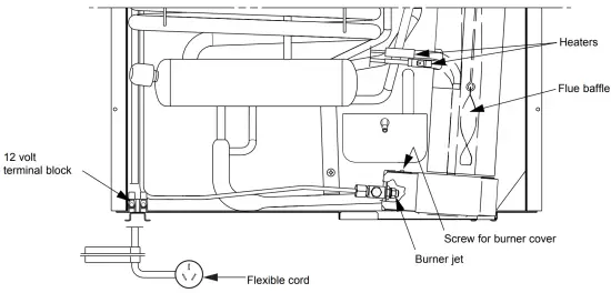
- Remove burner cover plate.
- Open the gas valve by turning knob A to position (GAS) without pushing the buttons C and D
- Apply a non-corrosive commercial bubble solution to the burner jet.
- No bubbles should appear at the opening of the burner jet. The presence of bubbles indicates a defective gas safety shutoff, and service is required.
If no bubbles were present at the burner jet, the gas safety valve is working properly. - Rinse jet thoroughly with fresh water before proceeding. Be careful not to damage the burner jet.
- Replace cover and turn the main switch OFF and back ON.
- Normal operation of the burner should return. Allow the burner to operate for a minimum of 5 minutes.
ELECTRICAL CONNECTION
The electrical installation must be carried out in a proper and durable manner, taking into account all relevant regulations and codes of practice.
For mains voltage operation, it is important that the circuit to and in the caravan is effectively earthed.
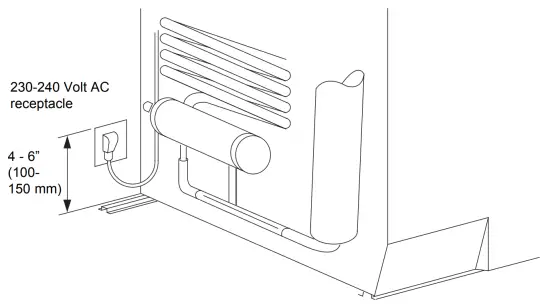
The refrigerator is equipped with a three-prong (grounding) plug for your protection against shock hazards and should be plugged directly into a properly grounded threeprong receptacle. Note! Do not cut or remove the grounding prong from this plug.
The free length of the cord is 6 ft. (1,8 m). It is recommended the receptacle placed on the left side of the refrigerator (viewed from the rear) and approximately 4-6 inches (100- 150 mm) from the floor. This will allow easy accessibility through the vent door.
230-240 V supplies
Check that the voltage stated on the data plate is the same as the main voltage in use (230-240 V). Plug the 230-240 Vrefrigerator power cord into an easily accessible wall socket. Electrical leads must be routed and secured so that they cannot come into contact with hot or sharp parts of the refrigerator.
Exchange of supply cord
If the supply cord is damaged, it must be replaced by the manufacturer, its service agent or similarly qualified persons in order to avoid a hazard.
12 Volts DC Supplies
The connection is made to the terminal block marked “12 volts DC” located at the bottom left corner on the back of the refrigerator.
To avoid a voltage drop, the cross sectional area of the connecting wires between battery and refrigerator must be at least 6 mm2 .
To ensure safe operation, the positive lead must be fitted with a fuse rated at 20 amps.
Correct polarity must be observed when connecting to the 12 V DC supply.
Note! Do not use the body or chassis of the vehicle as a substitute for either of the two conductors. Electrical leads must be routed and secured so that they cannot come into contact with hot or sharp parts of the refrigerator.
Do not connect any other electrical equipment or lighting to the refrigerator circuit.
The connections must be clean, tight and free from corrosion. If not, a resulting voltage drop will cause a decreased cooling capacity.
Note! Do NOT operate the refrigerator on 12 V when the vehicle is parked. The amperage draw of the 12 V DC heating element can discharge a battery in a very short time.
The installation of a 12 V DC operated refrigerator requires a relay to be installed on the tow vehicle or in the caravan. The relay will automatically shut off the 12 V DC power to the refrigerator when the ignition is turned off.

Before leaving
Once the installation is complete, test the operation of the refrigerator and instruct the user on its correct operation. If the appliance fails to operate correctly, contact your local Dometic Service provider.
RE-HINGING THE DOOR
To re-hinge the door, follow these steps:
- Before working on the refrigerator, make sure the 230- 240 V AC voltage and 12 V DC voltage leads are disconnected.
- Detach the top decor panel by removing the two mounting screws and the two knobs. Disengage seal strips. Remove the panel and place it aside.
- Use a socket wrench to loosen the upper hinge pin. Remove pin and save for later use.
- Lift door off the lower hinge pin. Place door on soft material to prevent any damage to the door.
- Remove lower hinge pin and insert into hinge hole on new hinge.
- Remove lower hinge by unscrewing the three screws. Save screws for later use.
- Remove plugs that cover the screw holes located on the side opposite of the present hinge location.
- Fasten the new hinge with the three screws removed earlier.
- Insert plugs to cover the unused screw holes on the opposite side
- Unscrew screws and remove upper hinge and travel catch. Save screws for reinstallation.
- Flip travel catch upside down and install on the opposite side of its present location.
- Install a new hinge. Fasten with the screws removed earlier.
- Locate the door. Remove plug and latch retainer on the top of the door. Replace in opposite positions.
- Place door on lower hinge pin. Mount upper hinge pin and fasten it using a socket wrench.
- Locate top decoration panel and detach the travel catch. Replace in opposite position.
- Fit top decoration panel and reinstall screws, knobs and seal strips.
- Check the travel catch to make sure it works properly, that the door closes easily and that the gasket seals well on all sides.
MOUNTING THE DOOR PANEL
The refrigerator is normally delivered without door panel and it is advisable to mount the panel before the refrigerator is installed in the enclosure.
Before starting the mounting work, read this instruction thoroughly and check that the panel dimensions are in compliance with those given in the following table:
| PANEL DIMENSIONS Max thickness 5/32 (4 mm) | ||||
| Height | Width | |||
| max | min | max | min | |
| inch | 26-17/64 | 26-3/16 | 19-5/8 | 19-17/32 |
| mm | 667 | 665 | 498 | 496 |
To mount the panel, follow these steps:
- Remove the screws from the top door cover strip and remove the cover strip by pulling straight upward.
- Slide the panel from the top of the door into the grooves on the vertical edges of the door sliding downwards until the panel fits into the lower door edge.
- Replace the top cover strip and fasten with screws.
REFRIGERATOR REMOVAL
- Before working on the refrigerator, make sure the 230- 240 V AC voltage and 12 V DC voltage leads are disconnected.
- Shut off the gas supply at the ULP gas bottle.
- Disconnect the gas supply line. Always use a back up wrench when loosening and tightening connections.
- Cap the gas supply line, loosen the screws anchoring the refrigerator to the enclosure and slide the refrigerator out of the compartment.
- When replacing the refrigerator make sure that the sealing strips are properly positioned.
- Replacement is the reverse of removal. Check all connections for gas leaks.
OPERATING INSTRUCTIONS
ABSORPTION REFRIGERATOR SYSTEM
In an absorption refrigerator system, ammonia is liquefied in the finned condenser coil at the top rear of the refrigerator. The liquid ammonia then flows into the evaporator (inside the freezer section) and is exposed to a circulating flow of hydrogen gas, which causes the ammonia to evaporate, creating a cold condition in the freezer
The tubing in the evaporator section is specifically sloped to provide a continuous movement of liquid ammonia, flowing downward by gravity through this section.
If the refrigerator is operated when it is not level and the vehicle is not moving, liquid ammonia will accumulate in sections of the evaporator tubing. This will slow the circulation of hydrogen and ammonia gas, or in severe cases, completely block it, resulting in a loss of cooling.
Note! Any time the vehicle is parked for several hours with the refrigerator operating, the vehicle must be levelled to prevent this loss of cooling.
When the vehicle is moving, the levelling is not critical, as the rolling and pitching movement of the vehicle will pass to either side of level, keeping the liquid ammonia from accumulating in the evaporator tubing.
GENERAL ADVICE AND INFORMATION
- Make sure defrosting is carried out periodically
- The refrigerator should be kept clean and dry with the door left open when it is not to be used for some time.
- Ensure that liquids or items with a strong odour are well packaged.
- Service and maintenance must be done on a regular schedule to keep the refrigerator operating properly, efficiently and safely. The service should be performed by qualified personnel only.
- Avoid spraying water through the refrigerator vents while washing your RV.
| WARNING |
| The sealed cooling system must not be opened. It contains corroding chemicals under high pressure. |
Sodium chromate is used for corrosion protection (less than 2 weight % of the coolant).
CONTROL PANEL
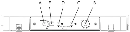
A. ON/OFF, Fuel selector switch
B. Thermostat knob, Gas/Electric
C. Flame failure safety valve push-button
D. Piezo igniter
E. Flame indicator
GAS, AC AND DC OPERATION
UNIVERSAL LP GAS OPERATION
Before starting the refrigerator, open the shutoff valve of the gas bottle (check that there is enough gas). Open any onboard shutoff valve.
- Start the refrigerator by turning turn knob A to position
 (GAS).
 - Turn the thermostat knob B to position 4.
- Press and hold button C and push button D for the piezo igniter several times to light the burner. This can be observed on the flame indicator E. When the flame is lit, the red indicator is in the green field. (ON).
- After the gas is lit keep button C pressed for 10 s. Release the button and check that the red indicator is in the green field, (ON).
Note! After changing an ULPG tank, or after a long shut off period, the gas line is likely to be filled with air. You may have to repeat the lighting procedure several times to purge the air out of the gas lines.
| ⚠ WARNING |
| Whilst mobile: – Do not operate the refrigerator on ULP gas. – Turn off the gas bottle. |
230-240 V AC OPERATION
Before operating the refrigerator, check that the voltage stated on the data plate is the same as the main voltage in use.
- ☞ Check to be sure that the power cord is properly connected to the power supply.
- Turn the knob A to the position marked “AC” for 230-240 volt AC operation.
- Turn the thermostat knob B to position 4.
12 V DC OPERATION
Only operate your refrigerator on 12 V DC when the engine of the vehicle is running – otherwise your battery will soon be discharged.
☞ Turn the knob A to the position marked “DC” for 12 V DC operation. Note that there is no thermostat function on 12 V
DC operation, the refrigerator works continuously.
REGULATING THE TEMPERATURE
The refrigerator is equipped with a thermostat that can be adjusted by turning the knob B to different setting to maintain the desired cabinet temperature.
ULP gas operation
- At “OFF, the thermostat closes its main valve and the burner runs continuously at the bypass rate, just enough to keep the burner lit.
- At “MAX”, the thermostat allows the burner to remain on high flame continuously.
AC operation (230-240 V AC)
- At “OFF, the contacts in the thermostat are open and the heating elements are off.
- At “MAX”, the heating element is “ON” continuously. Lowest cabinet and freezer temperatures are obtained at this setting.
The thermostat can be adjusted between “MAX” and “OFF” to obtain the desired cabinet temperature. The closer the knob is to “MAX” – the colder the cabinet temperature. The closer the knob is to “OFF” – the warmer the cabinet temperature.
When the thermostat reaches the set temperature, it will cut the burner back to bypass or, in electric operation (230240 V AC), shut off the heating element. The setting of the thermostat is not critical, but we recommend it be adjusted to maintain a dry frost on the cooling fins. Adjust the thermostat knob closer to “MAX” when the outside temperature becomes warm.
TURNING OFF THE REFRIGERATOR
☞ To shut off the refrigerator turn the knob A to “OFF”.
If the refrigerator will not be in operation for a period of weeks, it should be emptied, defrosted, cleaned and the door left ajar. Use the travel catch to hold in this position. The ice tray should also be dried and kept outside the cabinet.
STORAGE COMPARTMENTS
| ⚠ WARNING |
| Do not store explosive substances in the refrigerator, such as cigarette lighter gas, gasoline, ether or the like. |
FOOD STORAGE COMPARTMENT
The food storage compartment is completely closed and unventilated, which is necessary to maintain the required low temperature for food storage. Consequently, foods having a strong odour or those that absorb odours easily should be covered. Vegetables, salads etc. should be covered to retain their crispness
The coldest positions in the refrigerator are under the cooling fins and at the bottom of the refrigerator. The warmer areas are on the upper door shelves. This should be considered when placing different types of food in the refrigerator.
FROZEN FOOD STORAGE COMPARTMENT
Quick frozen soft fruits and ice cream should be placed in the coldest part of the compartment, which is at the bottom of the aluminium liner. Frozen vegetables, may be stored in any part of the compartment. This compartment is not designed for deep or quickfreezing of food. Meat or fish, whether raw or prepared, can be stored in the frozen food storage compartment provided they are precooled first in the refrigerator.
They can be stored about three times longer in the frozen food compartment as compared to the fresh food compartment. To prevent food from drying out, keep it in covered dishes, containers, plastic bags or wrapped in aluminium foil. Ice cubes can be made in the freezer compartment. For faster ice making, the tray should be placed in direct contact with the bottom of the freezer compartment. Ice making is accelerated if the thermostat knob B is turned to the “MAX” setting.
It is a good idea to do this a few hours before the anticipated need for ice, but be sure to turn the thermostat back to normal setting, usually about mid-setting when the ice is formed.
Food in the lower compartment may be frozen if the setting is left on “MAX” position.
REMOVING AND REPLACING THE SHELVES
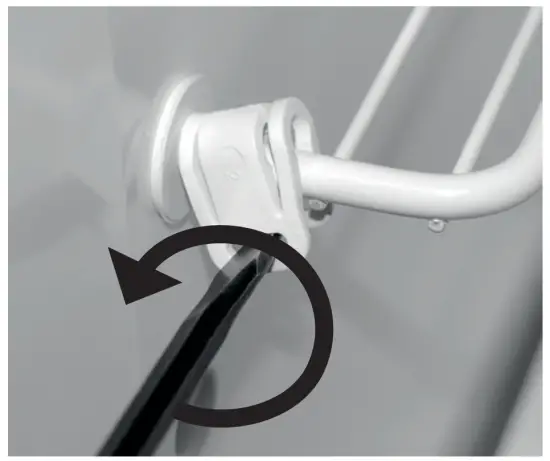
- ☞ Remove the shelf locks by inserting the tip of a flat bladed screwdriver into the slot of the locks. Turn the screwdriver counterclockwise and then remove the shelf locks from the wire shelf.
- Tilt the shelf to one side at an angle while pulling forward.
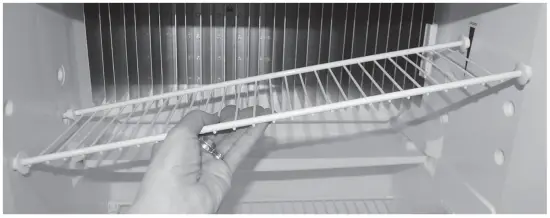
- Reposition the shelf in the desired location. Insert
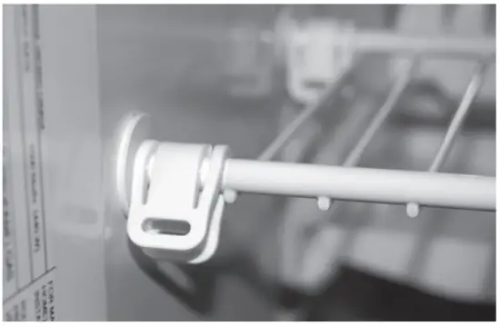
the ends of the wire shelf on the left-hand side and slide the shelf into the holes on the right-hand side. - Slide the plastic plugs into the holes of the wall.
- Snap the shelf locks onto the wire shelf.
PRODUCT CARE
DEFROSTING
- Shut off the refrigerator by turning the knob A to “OFF” position.
- Empty the refrigerator, leaving the drip tray under the finned evaporator.
- Leave the cabinet and freezer doors open. Filling the ice tray with hot water and placing it on the freezer shelf can reduce defrosting time.
Defrost water
Defrost water runs from the drip tray to a receptacle at the rear of the refrigerator where it normally evaporates. With a lot of defrost water as a result of heavy frosts build up on the cooling fins, remove the drip tray and turn it around. Replace the drip tray with the outlet on the right side of the drip tray and put a bowl under the outlet.CAUTION Do not use: - A knife or an ice pick, or other sharp tools to remove frost from the freezer shelves. It can create a leak in the ammonia system.
- A hot air blower. Permanent damage could result from warping the metal or plastic parts.
- When the ice has melted, dry the interior of the refrigerator with a clean cloth.
- Replace the drip tray to its original position and connect the draining tube.
- Replace all food and set the thermostat to “MAX” for a few hours. Then reset the thermostat to the desired setting, usually at mid-settings
CLEANING THE REFRIGERATOR
Always keep the refrigerator clean. Cleaning the refrigerator is usually done after it is defrosted or put into storage.
To clean the interior liner of the refrigerator, use lukewarm weak soda solution. Use only warm water to clean the finned evaporator, gasket, ice tray and shelves.
Note! Never use strong chemicals or abrasives to clean these parts, as the protective surfaces will be damaged.
It is important to keep the area at the back of the refrigerator clean. Check the lower vent, upper vent and area between these openings for any obstructions such as bird/insect nests, spider webs, etc. Clean the coils on the back of the refrigerator. Use a soft bristled brush to dust off the coils. Keep the refrigerator area free from combustible material, gasoline and other flammable vapours or liquids.
MAINTENANCE and SERVICE
Service and maintenance must be done on a regular schedule to keep the refrigerator operating properly, efficiently and safely. The service should only be performed by a qualified electrical or gas technician.
REPLACING THE HEATER
The refrigerator is equipped with two electrical heaters, one for 230-240 VAC and one for 12 V DC. To replace the heater proceed as follows:
- Unplug the refrigerator power cord from the 230240 volt AC outlet. Disconnect the 12 V DC power to the refrigerator.
- Remove the refrigerator from the enclosure.
- Disconnect the heater leads at the top of the refrigerator.
- With a pair of pliers, unfold the lug holding the lid of the boiler casing and open the lid.
- Remove some insulation wool so that the heater is accessible.
- Turn and lift the heater out of its pocket.
- Fit the new heater into the pocket.
- Reconnect the heater leads at the top.
- Put back the insulation and close the lid of the boiler.
- Reinstall the refrigerator in the enclosure.
- Check all connections for gas leaks.
- A qualified gas fitter should be employed.
- Connect 230-240 V power cord to the outlet.
- Reconnect or turn on the 12 V DC power.
PERIODIC MAINTENANCE
This work should be made by a qualified service man.
CHECKING THE CONNECTIONS
Check all connections in the ULP gas system (at the back of the refrigerator) for gas leaks. The ULP gas supply must be turned on. Apply a non-corrosive bubble solution to all ULP gas connections. The appearance of bubbles indicates a leak and should be repaired immediately by a qualified gas fitter.
CHECKING THE ULP GAS PRESSURE
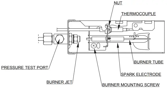
The ULP gas pressure should be checked and the main regulator readjusted if pressure is incorrect. The correct operating pressure is 2,7 kPa. The correct place to measure the ULP gas pressure is at the test port just ahead of the burner jet.
CLEANING THE FLUE AND BURNER
Maintenance work should be made by a qualified service man.
Inspect the flue baffle. It should be reasonably clean and free of soot. Heavy soot formation indicates improper functioning of the burner.
The flue and burner both require cleaning in the following manner:
- Unplug the refrigerator power cord from the 230240 V AC outlet. Disconnect or shut off the 12 V DC power to the refrigerator.
- Close the gas valve by turning the knob A to “OFF”.
- Remove cover from the burner housing.
- Disconnect the wire from the high voltage electrode.
- Remove the burner mounting screw and remove the burner assembly.
- Lift out the wire and flue baffle from the top of flue tube.
- Clean the flue from the top using a flue brush.
Blowing compressed air into the flue will not properly clean soot and scale out of the flue tube. - Replace the flue baffle.
- Clean burner tube with a brush. Blow out burner with compressed air.
⚠ WARNING Do not use a wire or pin when cleaning the burner jet as damage can occur to the precision opening. This can cause damage to the refrigerator or create a fire hazard. 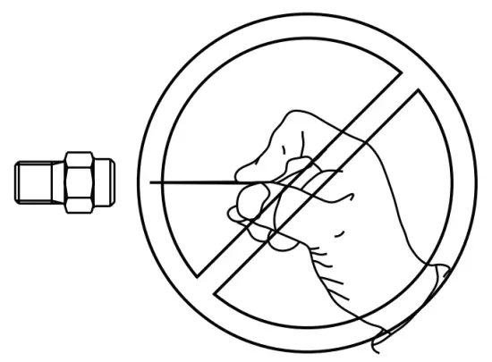
- Before removing burner jet, clean burner area of soot and scale that fell out of flue tube.
- Remove the burner jet. Soak the jet in wood alcohol and blow out with compressed air. Reinstall and tighten burner jet.
- Reinstall burner, being careful that the end of the burner fits into the slot on the burner bracket.
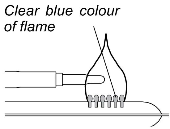
- Check to make sure the slots are centred under the flue tube and that the thermocouple is positioned properly (tip of thermocouple extends over two slots of burner). Note that the colour of the flame should be clear blue over the slots of the burner.
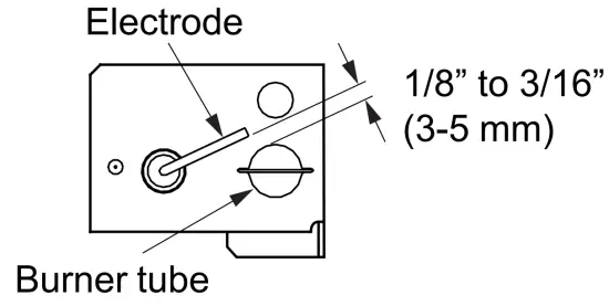
- Be sure to reconnect the wire to high voltage electrode. Check the electrode for proper location and gap.
- Open the gas valve by turning knob A to (GAS).
- Check all fittings for leaks with soapy water.
- Connect 230-240 volt power cord to the outlet and reconnect the 12 V DC power.
- Check ULP gas safety shutoff.
TROUBLESHOOTING
REFRIGERATOR DOES NOT COOL PROPERLY
- Burner jet clogged.
- Check level of refrigerator.
- Venting problem.
- Heavy frost buildup on evaporator fins.
- Flue baffle not inserted properly in flue tube.
- Improperly set thermostat.
- Burner dirty.
- ULP gas pressure low at burner. (Set main regulator so pressure does not drop below 2,7 kPa at pressure tap.)
- Burner not located properly under flue tube.
- Burner damaged.
ODOUR FROM FUMES - Dislocated burner
- Damaged burner
- Dirty flue tube
APPENDIX
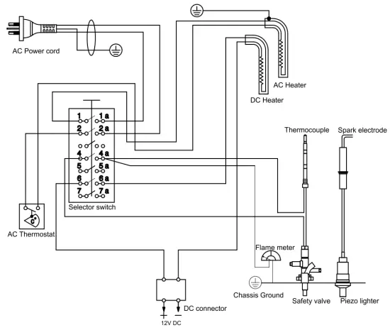
REARVIEW EQUIPMENT
WIRING DIAGRAM
dometic.com
YOUR LOCAL
DEALER
dometic.com/dealer
YOUR LOCAL
SUPPORT
dometic.com/contact
OUR LOCAL
SALES OFFICE
dometic.com/sales-offices
A complete list of Dometic companies, which comprise the Dometic Group, can be found in the public filings of:
DOMETIC GROUP AB Hemvärnsgatan 15 SE-17154 Solna Sweden