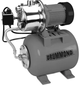
DRUMMOND 1 HP Stainless Steel Shallow Well Pump and Tank
Save This Manual Keep this manual for the safety warnings and precautions, assembly, operating, inspection, maintenance and cleaning procedures. Write the product’s serial number in the back of the manual near the assembly diagram (or month and year of purchase if product has no number).
Keep this manual and the receipt in a safe and dry place for future reference.
Do not return pump to the store. Call 1-844-416-9141
Visit our website at: http://www.harborfreight.com
Email our technical support at: [email protected]
When unpacking, make sure that the product is intact and undamaged. If any parts are missing or broken, please call 1-888-866-5797 as soon as possible.
 |
| Read this material before using this product. Failure to do so can result in serious injury. SAVE THIS MANUAL. |
Before start-up, note the following:
The pump must be connected to a GFCI protected plug which has been installed according to regulations. The plug must have a supply voltage of 120 VAC at 60 Hz.
CAUTION
This pump has been evaluated for use with water only
WARNING
IMPORTANT! For your own safety before starting to run the pump, please have the following items checked by an expert:
- Risk of electric shock This pump is supplied with a grounding conductor and grounding-type attachment plug. To reduce the risk of electric shock, be certain that it is connected only to a properly grounded, grounding-type receptacle.
- Risk of electric shock This pump has not been investigated for use in swimming pool areas.
- The electrical connections must be protected from moisture.
- If there is danger of flooding, the electrical connections must be taken to higher ground.
- Circulation of caustic fluids, as well as the circulation of abrasive materials, must be avoided at all costs.
- The pump must be protected from frost.
- The pump must be protected from running dry
- Access by children should also be prevented with appropriate measures.
 To prevent death from electric shock, pump must be connected only to a GFCI protected outlet.
- Do not use an extension cord with this item
- People with pacemakers should consult their physician(s) before use. Electromagnetic fields in close proximity to heart pacemaker could cause pacemaker interference or pacemaker failure
- The warnings, precautions, and instructions discussed in this instruction manual cannot cover all possible conditions and situations that may occur. It must be understood by the operator that common sense and caution are factors which cannot be built into this product, but must be supplied by the operator.
Fluid Type
The Pump is designed for use with water with a maximum temperature of 77° F (25°C). Do not use the pump for other fluids, especially not fuels, cleaning fluids, or other chemical products.
Specifications
| Electrical Rating | 120VAC / 60Hz / 10A |
| Power Cord Length | 6’ |
| Maximum Flow @ 0’ | 950 GPH |
| Maximum Head lift @ 0 Flow | 115.5′ |
| Discharge Port | 1″ NPT Thread |
Installation
The pump must be installed in a stationary position with either:
a. A fixed pipeline or
b. A flexible hose pipe.
Please note!
- Do not install the pump by suspending it unsupported from its delivery pipe or power cord. The pump must be suspended from the handle or be placed on the bottom of the basin. To ensure that the pump works properly, keep the bottom free from sludge and dirt of all kinds.
- If the water level sinks too low, any sludge in the basin will dry out and stop the pump from starting. To help ensure the pump will start as required, check the pump regularly with start-up tests.
Power Supply
- The pump is equipped with a shock-proof plug according to regulations. The pump is designed to be connected to 120 VAC, 60 Hz GFCI protected socket.
- Make sure that the socket is sufficiently secured and is in excellent condition.
- When the plug is inserted into the socket, the pump will be on standby.
- WARNING: To prevent death from electric shock, pump must be connected only to a GFCI protected outlet.
WARNING! TO PREVENT SERIOUS INJURY:
If the power cord or plug is damaged, do not use the pump. The power cord or plug may only be repaired by a certified electrician.
Areas of use
- This pump is designed to pump water only.
- This pump is designed to be used for: Pumping drinking water from shallow wells and cisterns. Irrigation systems.
- This pump should NOT be used for: Continuous run, fountain/pond water features. Water with dirt and debris.
- This pump can also be used to transfer water (e.g. household, farming, plumbing).
- Do not use as a booster pump in a city water system
Installation Instructions
This pump is designed for use as a well pump.
TO PREVENT SERIOUS INJURY FROM ELECTRIC SHOCK:
Install indoors or in weather-proof well house only. This Pump is non-submersible. Do not plug in the power cord when wet or standing on damp or wet ground. Do not plug in the power cord until instructed to do so.
a. ONLY pump clean water.
b. Additional components (such as valves and pipes) may be required for installation, but not included.
c. Installation requires skilled workmanship and compliance with local building codes.
If you are not confident in your ability to properly and safely install this pump, have a qualified technician perform the installation.
d. The water to be pumped must be clean and must be free of sand and grit, which would damage the pump and void the warranty.
- The illustration below shows an example of a proper shallow well pump installation. The total suction lift (vertical well lift + length of off-set line) must not exceed Maximum Suction Lift.
This pump is intended for shallow well application only and is not intended to be used as a booster pump.
For optimal performance, install the pump as close to the well head as possible.
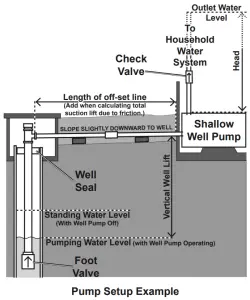
- Install a Foot Valve at the bottom of the suction pipe. The Foot Valve must be under the Pumping Water Level, the level that the water falls to when the pump operates.
- Install a sterile Well Seal at the top of the suction pipe to keep the well clean. Protect from rust inside a frost-proof enclosure.
- Intake and discharge pipes must be at least 1 in diameter.
- Lay an off-set line from the well to the structure the pump will be installed in. The off-set line should slope slightly towards the well. Systems with longer off-set lines should use larger diameter pipe to improve efficiency.
- Install the pump on a rigid, level, dry platform. This platform must provide a solid, level surface that is capable of supporting the weight of the pump and attached piping filled with water. Do not allow water to contact the pump’s housing.
NOTICE: DO NOT INSERT fittings into the Intake Hole farther than 1/2; this can DAMAGE the Pump, diminish Pump functions, and/or STOP water flow. - To prevent leaks, use metal fittings for all pipe conections to pump ports. Do not use plastic fittings.
- Keep the Head, the height that the pump discharge must push water before discharge, to a minimum. The Vertical Well Lift, Off-set Line Length, and Head added together must be less than Maximum Delivery Height to have flow at output. Effective flow decreases to 0 GPH as Maximum Delivery Height reaches its maximum.
- For your protection, the power outlet used should have a Ground Fault Circuit Interrupter (GFCI). Have it installed by a qualified electrician. Keep power line away from water.
- The inlet and discharge lines should not be wedged or stressed in a way that puts strain on the pump. Do not support the pump with the inlet or discharge lines.
Operation
After reading these instructions, consider the following points before starting the pump:
- The Compression Tank has a rubber bladder inside that has been pressurized to 23 PSI. Remove the cover over the air valve (on the tank end opposite the pipe connection) and periodically monitor this air valve with an air pressure gauge to ensure that the rubber bladder maintains the required air pressure. Air can be added using a bicycle pump.
- Make sure the intake pipe is fully submerged before continuing.
- Before starting the pump for the first time, prime it as follows:
a. Fill the suction Pipe and Pump Body through the Priming Inlet.
b. Close the Inlet after verifying that there are no leaks.
c. Open the spigots, faucets and/or taps on the Delivery Pipe so that air can be release from the suction cycle. - This is a self-starting pump that uses a pressure switch. Once the power cord is connected, the pump can start at any time.
Do not handle or perform maintenance on the pump if the power cord is plugged in. - Verify that the pump rests on the floor of the basin, if it is not suspended by the handle.
- Verify that the discharge pipe is properly connected.
- Verify that the electrical connection is 120 VAC, 60 Hz.
- Verify that the electrical socket is GFCI protected and in good condition. Test GFCI protected outlet before use.
- Verify that water and moisture cannot get near the power supply socket.
- Verify that the pump is installed so as to prevent running dry.
- Run pump for two minutes. If it fails to pump water, disconnect power, re-fill pump body through priming inlet and re-start
- To begin pumping, plug in the power cord. When the line is pressurized, the pump will go to standby mode until the pressure falls below its starting pressure.
Maintenance
TO PREVENT SERIOUS INJURY FROM ACCIDENTAL OPERATION: Unplug the Pump from its electrical outlet before performing any inspection, maintenance, or cleaning procedures.
If the pump is moved during operation, flush it out with clean water after every use.
Quarterly Maintenance
The below maintenance must be performed at least once every 3 months under optimal conditions. For frequent use, or dirty areas, more frequent maintenance is required.
- Clean the inlet screen on the intake port regularly to remove accumulated debris.
- Wipe the pump clean with a soft, damp cloth with soapy water. Do not use solvents. Do not get the electrical components wet.
- Drain water from pump before storage by disconnecting the water lines and turning the Pump upside down. If storing the pump for a long time, store it in a dry location, and apply a light layer of oil to the metal parts prior to storage, to inhibit rust. Do not expose to freezing temperatures.
- After storage, check the Impeller to make sure it turns easily and is not oxidized.
Troubleshooting
| Problem | Cause | Solution |
| The pump won’t start |
|
|
| The pump operates but it won’t discharge water |
|
|
| Only a low volume
of water flows |
|
|
| Motor overheats often | Pump cycling too often. | Cut-in and cut-out pressure may be set too close together. Have the pressure switch adjusted by a qualified technician. |
| Pump/motor cycles rapidly | Cut-in and cut-out pressure may be set too closely. | Have the pressure switch adjusted by a qualified technician. |
| Tank bladder will not hold pressure |
|
|
| Water pumps intermittently | Water level is being drawn below foot valve. | Lower foot valve. |
| Pump will not hold prime |
|
|
| Water is full of
bubbles at outlet |
|
|
| Motor runs, but water is not pumping |
|
|
| Pump does not shut off |
|
|
 Follow all safety precautions whenever diagnosing or servicing the pump. Disconnect power supply before service. Follow all safety precautions whenever diagnosing or servicing the pump. Disconnect power supply before service.Do not disassemble the pump or motor as this will damage the water seals. All repairs should be performed by a qualified technician. |
||
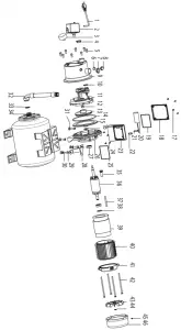
Parts List and Diagram
PLEASE READ THE FOLLOWING CAREFULLY
THE MANUFACTURER AND/OR DISTRIBUTOR HAS PROVIDED THE PARTS LIST AND ASSEMBLY DIAGRAM IN THIS MANUAL AS A REFERENCE TOOL ONLY. NEITHER THE MANUFACTURER OR DISTRIBUTOR MAKES ANY REPRESENTATION OR WARRANTY OF ANY KIND TO THE BUYER THAT HE OR SHE IS QUALIFIED TO MAKE ANY REPAIRS TO THE PRODUCT, OR THAT HE OR SHE IS QUALIFIED TO REPLACE ANY PARTS OF THE PRODUCT. IN FACT, THE MANUFACTURER AND/OR DISTRIBUTOR EXPRESSLY STATES THAT ALL REPAIRS AND PARTS REPLACEMENTS SHOULD BE UNDERTAKEN BY CERTIFIED AND LICENSED TECHNICIANS, AND NOT BY THE BUYER. THE BUYER ASSUMES ALL RISK AND LIABILITY ARISING OUT OF HIS OR HER REPAIRS TO THE ORIGINAL PRODUCT OR REPLACEMENT PARTS THERETO, OR ARISING OUT OF HIS OR HER INSTALLATION OF REPLACEMENT PARTS THERETO.
Parts List
| Part | Description | Qty. |
| 1 | Plug and Cable | 1 |
| 2 | Pressure Switch | 1 |
| 3 | Pressure Gauge | 1 |
| 4 | Dust Cover | 1 |
| 5 | Screw | 8 |
| 6 | O-Ring | 1 |
| 7 | Dust Cover | 1 |
| 8 | Screw | 1 |
| 9 | Pump Body | 1 |
| 10 | O-Ring | 1 |
| 11 | Guiding Object | 1 |
| 12 | Nut | 1 |
| 13 | Impeller | 1 |
| 14 | O-Ring | 1 |
| 15 | Flange | 1 |
| 16 | Water Proof Ring | 1 |
| 17 | Bolt | 4 |
| 18 | Terminal Box | 1 |
| 19 | Seal | 1 |
| 20 | Capacitor | 1 |
| 21 | Bolt | 2 |
| 22 | Block | 1 |
| 23 | Bottom Cover | 1 |
| 24 | Bolt | 4 |
| 25 | Seal | 1 |
| 26 | Aluminum Front Cover | 1 |
| 27 | Ball Bearing | 2 |
| 28 | Support | 1 |
| 29 | Bolt | 4 |
| 30 | Gasket | 2 |
| 31 | Nut | 4 |
| 32 | Flexible Tube | 1 |
| 33 | Gasket | 1 |
| 34 | Tank | 1 |
| 35 | Sheath | 1 |
| 36 | Rotor | 1 |
| 37 | Cable | 1 |
| 38 | Gasket | 1 |
| 39 | Stator | 1 |
| 40 | Motor Box | 1 |
| 41 | Aluminum Cover | 1 |
| 42 | Bolt | 4 |
| 43 | Fan | 1 |
| 44 | Circlip | 1 |
| 45 | Bolt | 4 |
| 46 | Fan Cover | 1 |
Record Product’s Serial Number Here:
Note: If product has no serial number, record month and year of purchase instead.
Note: Some parts are listed and shown for illustration purposes only, and are not available individually as replacement parts. Specify UPC 792363634076 when ordering parts.
Assembly Diagram
Limited 90 Day Warranty
Harbor Freight Tools Co. makes every effort to assure that its products meet high quality and durability standards, and warrants to the original purchaser that this product is free from defects in materials and workmanship for the period of 90 days from the date of purchase. This warranty does not apply to damage due directly or indirectly, to misuse, abuse, negligence or accidents, repairs or alterations outside our facilities, criminal activity, improper installation, normal wear and tear, or to lack of maintenance. We shall in no event be liable for death, injuries to persons or property, or for incidental, contingent, special or consequential damages arising from the use of our product. Some states do not allow the exclusion or limitation of incidental or consequential damages, so the above limitation of exclusion may not apply to you. THIS WARRANTY IS EXPRESSLY IN LIEU OF ALL OTHER WARRANTIES, EXPRESS OR IMPLIED, INCLUDING THE WARRANTIES OF MERCHANTABILITY AND FITNESS.
To take advantage of this warranty, the product or part must be returned to us with transportation charges prepaid. Proof of purchase date and an explanation of the complaint must accompany the merchandise. If our inspection verifies the defect, we will either repair or replace the product at our election or we may elect to refund the purchase price if we cannot readily and quickly provide you with a replacement. We will return repaired products at our expense, but if we determine there is no defect, or that the defect resulted from causes not within the scope of our warranty, then you must bear the cost of returning the product. This warranty gives you specific legal rights and you may also have other rights which vary from state to state.

26541 Agoura Road · Calabasas, CA 91302 · 1-888-866-5797