E-flite Turbo Timber Evolution 1.5m Instruction Manual


NOTICE
All instructions, warranties and other collateral documents are subject to change at the sole discretion of Horizon Hobby, LLC. For up-to-date product literature, visit horizonhobby.com or towerhobbies.com and click on the support or resources tab for this product.
MEANING OF SPECIAL LANGUAGE
The following terms are used throughout the product literature to indicate various levels of potential harm when operating this product:
WARNING: Procedures, which if not properly followed, create the probability of property damage, collateral damage, and serious injury OR create a high probability of superficial injury.
CAUTION: Procedures, which if not properly followed, create the probability of physical property damage AND a possibility of serious injury.
NOTICE: Procedures, which if not properly followed, create a possibility of physical property damage AND little or no possibility of injury.
![]() WARNING: Read the ENTIRE instruction manual to become familiar with the features of the product before operating. Failure to operate the product correctly can result in damage to the product, personal property and cause serious injury. This is a sophisticated hobby product. It must be operated with caution and common sense and requires some basic mechanical ability. Failure to operate this Product in a safe and responsible manner could result in injury or damage to the product or other property. This product is not intended for use by children without direct adult supervision. Do not use with incompatible components or alter this product in any way outside of the instructions provided by Horizon Hobby, LLC. This manual contains instructions for safety, operation and maintenance. It is essential to read and follow all the instructions and warnings in the manual, prior to assembly, setup or use, in order to operate correctly and avoid damage or serious injury.
WARNING: Read the ENTIRE instruction manual to become familiar with the features of the product before operating. Failure to operate the product correctly can result in damage to the product, personal property and cause serious injury. This is a sophisticated hobby product. It must be operated with caution and common sense and requires some basic mechanical ability. Failure to operate this Product in a safe and responsible manner could result in injury or damage to the product or other property. This product is not intended for use by children without direct adult supervision. Do not use with incompatible components or alter this product in any way outside of the instructions provided by Horizon Hobby, LLC. This manual contains instructions for safety, operation and maintenance. It is essential to read and follow all the instructions and warnings in the manual, prior to assembly, setup or use, in order to operate correctly and avoid damage or serious injury.
AGE RECOMMENDATION: Not for children under 14 years. This is not a toy.
Safety Precautions and Warnings
As the user of this product, you are solely responsible for operating in a manner that does not endanger yourself and others or result in damage to the product or the property of others.
- Always keep a safe distance in all directions around your model to avoid
- Never operate your model with low transmitter batteries. collisions or injury. This model is controlled by a radio signal subject to interference from many sources outside your control. Interference can cause momentary loss of control.
- Always operate your model in open spaces away from full-size vehicles, traffic and people.
- Always carefully follow the directions and warnings for this and any optional support equipment (chargers, rechargeable battery packs, etc.).
- Always keep all chemicals, small parts and anything electrical out of the reach of children.
- Always avoid water exposure to all equipment not specifically designed and protected for this purpose. Moisture causes damage to electronics.
- Never place any portion of the model in your mouth as it could cause serious injury or even death.
- Always keep aircraft in sight and under control.
- Always use fully charged batteries.
- Always keep transmitter powered on while aircraft is powered.
- Always remove batteries before disassembly.
- Always keep moving parts clean.
- Always keep parts dry.
- Always let parts cool after use before touching.
- Always remove batteries after use.
- Always ensure failsafe is properly set before flying.
- Never operate aircraft with damaged wiring.
- Never touch moving parts.
![]() WARNING AGAINST COUNTERFEIT PRODUCTS: If you ever need to replace your Spektrum receiver found in a Horizon Hobby product, always purchase from Horizon Hobby, LLC or a Horizon Hobby authorized dealer to ensure authentic high-quality Spektrum product. Horizon Hobby, LLC disclaims all support and warranty with regards, but not limited to, compatibility and performance of counterfeit products or products claiming compatibility with DSM or Spektrum technology.
WARNING AGAINST COUNTERFEIT PRODUCTS: If you ever need to replace your Spektrum receiver found in a Horizon Hobby product, always purchase from Horizon Hobby, LLC or a Horizon Hobby authorized dealer to ensure authentic high-quality Spektrum product. Horizon Hobby, LLC disclaims all support and warranty with regards, but not limited to, compatibility and performance of counterfeit products or products claiming compatibility with DSM or Spektrum technology.
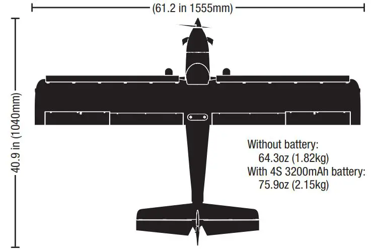
Specifications
If you own this product, you may be required to register with the FAA. For up-to-date information on how to register with the FAA, please visit https://registermyuas.faa.gov/. For additional assistance on regulations and guidance on UAS usage, visit knowbeforeyoufly.org/.
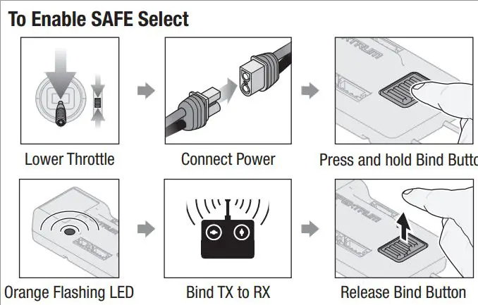
SAFE® Select Technology BNF
The BNF Basic version of this airplane includes SAFE Select technology which can offer an extra level of protection in flight. Use the following instructions to make the SAFE Select system active and assign it to a switch. When enabled, SAFE Select prevents the airplane from banking or pitching past predetermined limits, and automatic self-leveling keeps the airplane flying in a straight and level attitude when the aileron, elevator and rudder sticks are at neutral. SAFE Select is enabled or disabled during the bind process, or it can be enabled via Forward Programming. When the airplane is bound with SAFE Select enabled, a switch can be assigned to toggle SAFE Select ON or OFF. AS3X® technology remains active at all times.
SAFE Select can be configured three ways:
- SAFE Select Off: Always in AS3X mode
- SAFE Select On with no switch assigned: Always in SAFE Select mode
- SAFE Select On with a switch assigned
Preflight
- Remove and inspect contents.
- Read this instruction manual thoroughly.
- Charge the flight battery.
- Setup Transmitter using transmitter setup chart.
- Fully assemble the airplane.
- Install the flight battery in the aircraft (once it has been fully charged).
- Check the Center of Gravity (CG).
- Bind the aircraft to your transmitter.
- Make sure linkages move freely.
- Perform the Control Direction Test with the transmitter.
- Perform the AS3X Control Direction Test with the aircraft.
- Adjust flight controls and transmitter.
- Perform a radio system Range Test.
- Install the propeller and spinner.
- Find a safe open area to fly.
- Plan flight for flying field conditions.
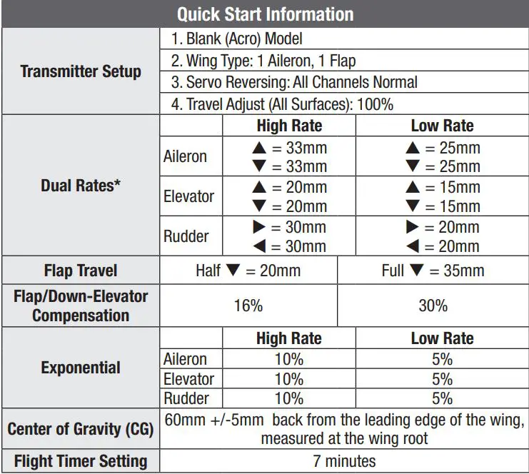
Transmitter Setup BNF
Dual Rates
Take first flights in Low Rate. For landings, use high rate elevator.
NOTICE: To ensure AS3X® technology functions properly, do not lower rate values below 50%. If lower rates are desired, manually adjust the position of the pushrods on the servo arm.
NOTICE: If oscillation occurs at high speed, refer to the Troubleshooting Guide for more information.
Exponential
After first flights, you may adjust expo in your transmitter.
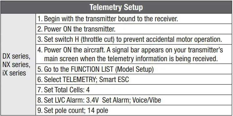
Telemetry Setup
See the Telemetry Setup table after binding. In order for the ESC and battery information to auto-populate in your transmitter’s telemetry menu, you must begin telemetry setup with the aircraft bound and connected.
![]()
* Flap programming values may vary slightly. For your initial flights use the recommended flap travel settings provided and adjust the flap travel to your preference on subsequent flights.
![]() WARNING: Assemble the aircraft, program your radio control system, bind the aircraft, and verify correct operation before installing the propeller. Never attempt to program the radio components, assemble the aircraft or perform maintenance of any kind without removing the propeller or engaging throttle cut. Serious injury could result if the motor starts inadvertently with the propeller still attached.
WARNING: Assemble the aircraft, program your radio control system, bind the aircraft, and verify correct operation before installing the propeller. Never attempt to program the radio components, assemble the aircraft or perform maintenance of any kind without removing the propeller or engaging throttle cut. Serious injury could result if the motor starts inadvertently with the propeller still attached.
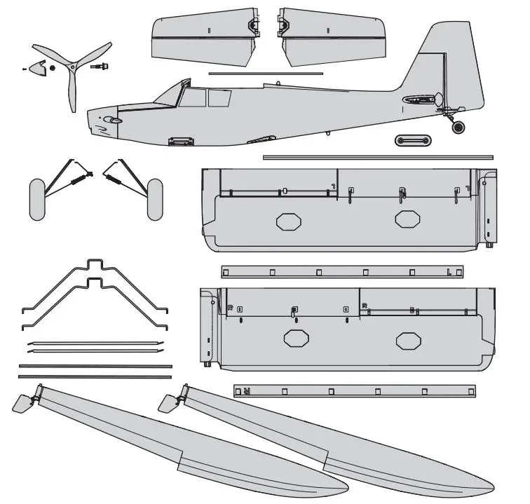
Model Assembly
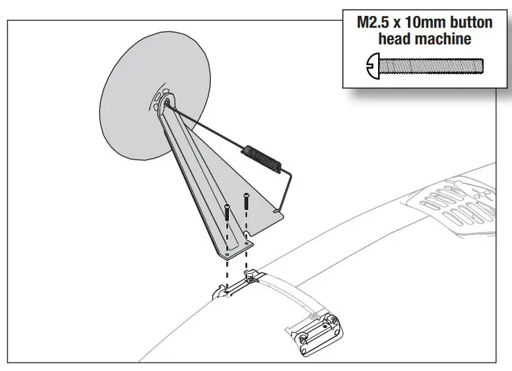
Landing Gear Installation
Mount the Landing Gear to the Fuselage
- Remove the spring clamp assembly and set it aside.
- Insert the left landing gear assembly into the pocket on the side of the fuselage as shown. The landing gear legs mount to the flat spot of the aluminum block which can pivot in the pocket.
- Thread the included M2.5 x 10mm machine screws through the landing gear leg into the threaded holes in the aluminum pivot block.
- Repeat the process to install the right landing gear assembly.
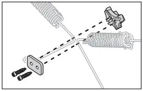
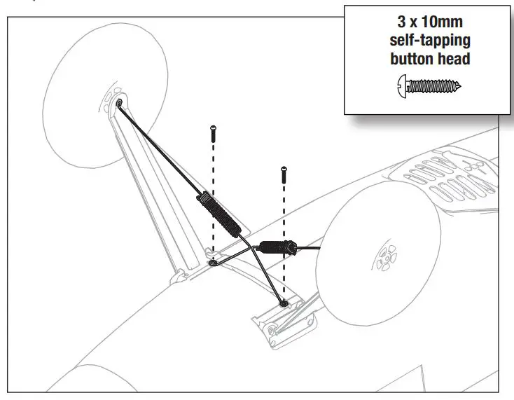
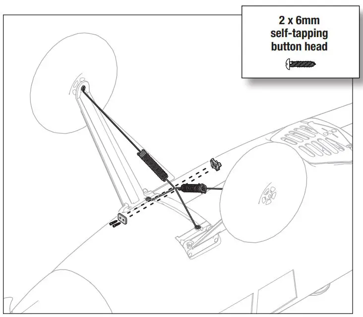
Mount the Spring Assemblies to the Fuselage
- Align the spring assemblies with the mounting holes in the fuselage. These assemblies mount to the plastic bracket pre-installed in the fuselage between the landing gear.
- Install the two 3 x 10mm self tapping screws to anchor the spring assemblies in place.
Clamp the Spring Assemblies Together
- Align the spring assemblies with the joiner bracket.
- Clamp the assembly together with the two 2 x 6mm self tapping screws.
Receiver Selection and Installation PNP
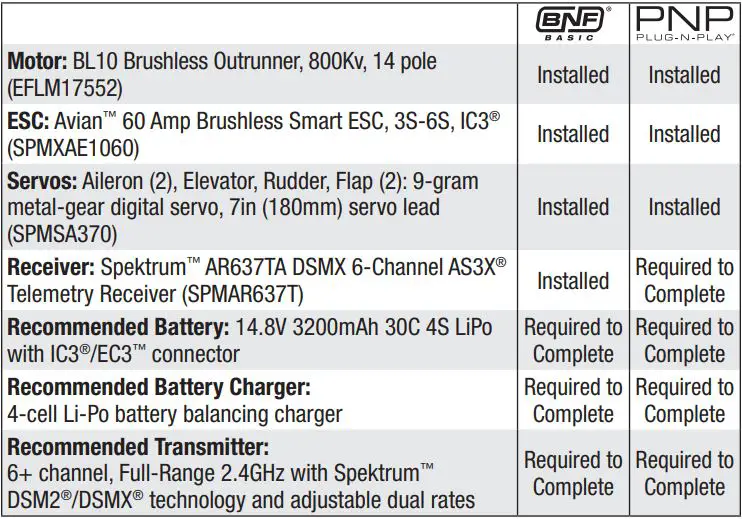
The recommended receiver for this aircraft is the Spektrum AR637T. If you choose to install a different receiver, ensure that it is at least a 6-channel full range receiver. Refer to the manual of your chosen receiver for correct installation and operation instructions.
AR637T Installation
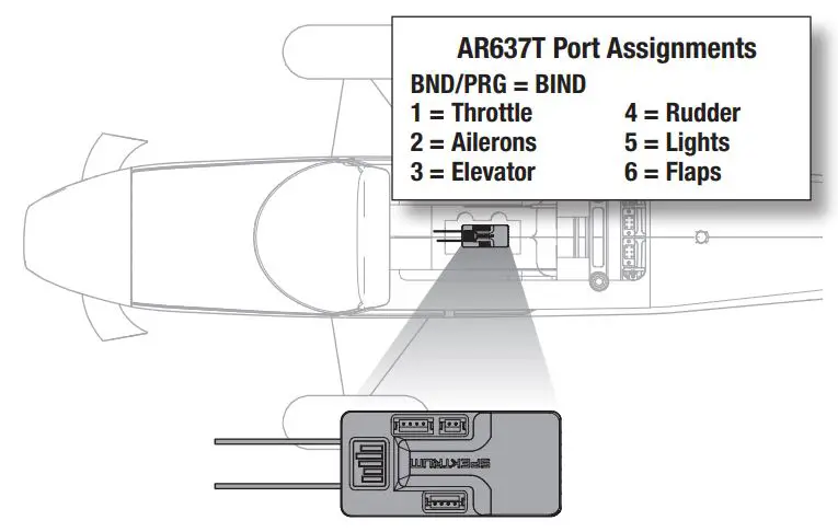
Attach the appropriate control surfaces to the their respective ports on the receiver using the table at the right.- Using high quality double-sided servo tape,(not included) mount the receiver to the flat area behind the battery compartment, as shown. The receiver should be mounted in the orientation shown, parallel to the length of the fuselage, with the label facing up and the servo ports facing the rear of the aircraft. The orientation of the receiver is critical for all AS3X and SAFE technology setups.
![]() CAUTION: Incorrect installation of the receiver could cause a crash.
CAUTION: Incorrect installation of the receiver could cause a crash.
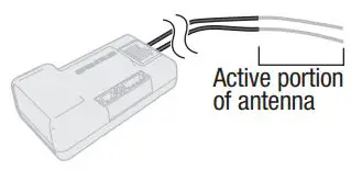
Antenna Installation
The AR637T receiver has a coaxial style antenna. We recommend installing the antenna as far as possible from metal, batteries, or carbon fiber to maximize signal reception performance.
NOTICE: Do not cut, kink, or modify the antenna. Damage to the coaxial portion of an antenna will reduce the performance of the antenna. Shortening or cutting off the 31mm tip will reduce the range.
General Binding Tips and Failsafe BNF
- The included receiver has been specifically programmed for operation of this aircraft. Refer to the receiver manual for correct setup if the receiver is replaced.
- Keep away from large metal objects while binding.
- Do not point the transmitter’s antenna directly at the receiver while binding.
- The orange LED on the receiver will flash rapidly when the receiver enters bind mode.
- Once bound, the receiver will retain its bind settings for that transmitter until you re-bind.
- If the receiver loses transmitter communication, the failsafe will activate. Failsafe moves the throttle channel to low throttle. Pitch and roll channels move to actively stabilize the aircraft in a descending turn.
- If problems occur, refer to the troubleshooting guide or if needed, contact the appropriate Horizon Product Support office.
Transmitter and Receiver Binding / Enabling and Disabling SAFE Select BNF
The BNF Basic version of this airplane includes SAFE Select technology, enabling you to choose the level of flight protection. SAFE mode includes angle limits and automatic self leveling. AS3X mode provides the pilot with a direct response to the control sticks. SAFE Select is enabled or disabled during the bind process. With SAFE Select disabled the aircraft is always in AS3X mode. With SAFE Select enabled the aircraft will be in SAFE Select mode all the time, or you can assign a switch to toggle between SAFE Select and AS3X modes. Thanks to SAFE Select technology, this aircraft can be configured for full-time SAFE mode, full-time AS3X mode, or mode selection can be assigned to a switch.
IMPORTANT: Before binding, read the transmitter setup section in this manual and complete the transmitter setup table to ensure your transmitter is properly programmed for this aircraft.
IMPORTANT: Move the transmitter flight controls (rudder, elevators, and ailerons) and the throttle trim to neutral. Move the throttle to low before and during binding. This process defines the failsafe settings.
You can use either the bind button on the receiver case or the conventional bind plug to complete the binding and SAFE Select process.
Using The Bind Button…
SAFE SELECT ENABLED: The control surfaces cycle back and forth twice with a slight pause at neutral position every time the receiver is powered on.
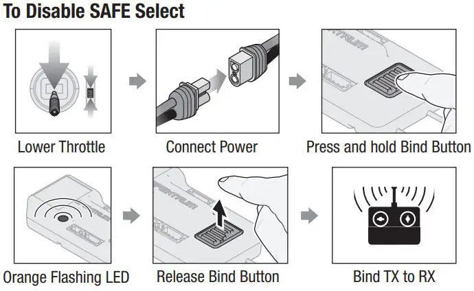
SAFE SELECT DISABLED: The control surfaces cycle back and forth once every time the receiver is powered on
Using The Bind Plug…
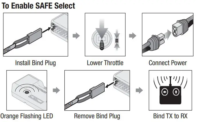
SAFE SELECT ENABLED: The control surfaces cycle back and forth twice with a slight pause at neutral position every time the receiver is powered on.
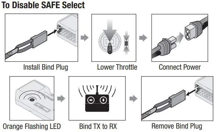
SAFE SELECT DISABLED: The control surfaces cycle back and forth once every time the receiver is powered on.
Model Assembly (continued)
Horizontal Stabilizer Installation
- Slide the horizontal stabilizer joiner (A) into the hole in the rear of the fuselage.
- Flex each of the elevators back and forth several times to break in the hinge.
- Install the two piece (left and right) horizontal stabilizer as shown. Ensure the control horn faces down.
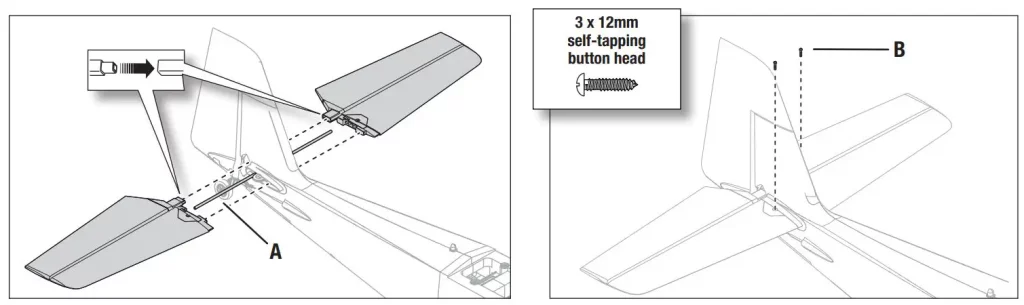
- Secure the horizontal stabilizer pieces in place using the two included 3 x 12 mm self tapping screws (B).
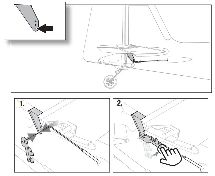
Pushrod keeper Installation
- Insert the end of the pushrod with the 90° bend into the outside hole of the control horn and insert the pushrod into the hole in the pushrod keeper.
- Rotate the pushrod keeper and press into place on the pushrod until it clicks into position.
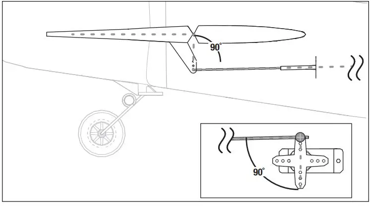
Control Surface Centering
After assembly and transmitter setup, confirm that the control surfaces are centered. The model must be powered up and bound to the transmitter in AS3X mode, keeping the throttle at zero. When enabled, SAFE mode is active at power up. AS3X mode is activated when the throttle is raised above 25% for the first time after being powered on. It is normal for the control surfaces to respond to aircraft movement if the aircraft is in AS3X or SAFE modes.
- Verify the trims and sub trims on your transmitter are zero.
- Power up the model in AS3X mode and leave the throttle at zero, the control surfaces need to be centered.
- If they are not centered, loosen the screw in the quick connector linkage on the servo horn.
- Slide the pushrod in the quick connector to change the length of the linkage between the servo arm and the control horn so the control surface is centered.
- Apply thread lock compound to the screw threads and tighten the screw to secure the pushrod at the desired length.
Model Assembly (continued)
Wing Assembly
Choose to assemble the wing with or without the leading edge slats to suit your flying style. For optimized high speed performance we recommend flying without the slats. For maximum slow speed performance we recommend installing the slats.
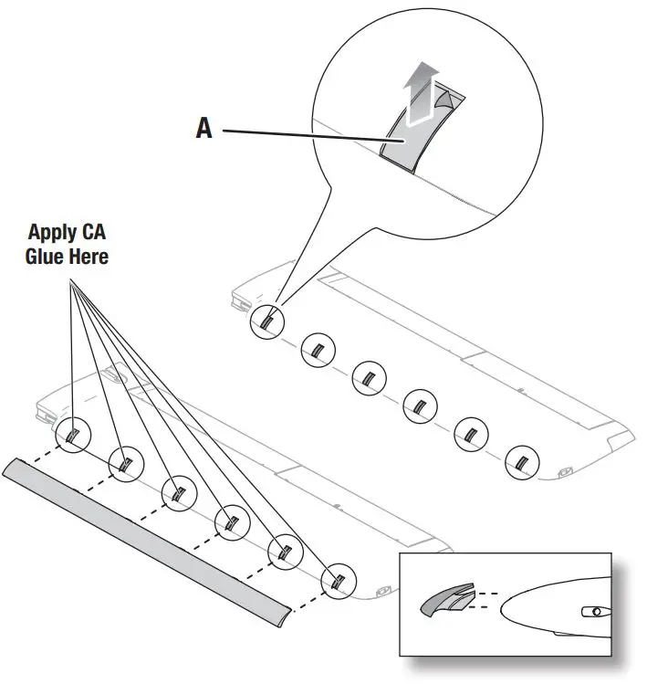
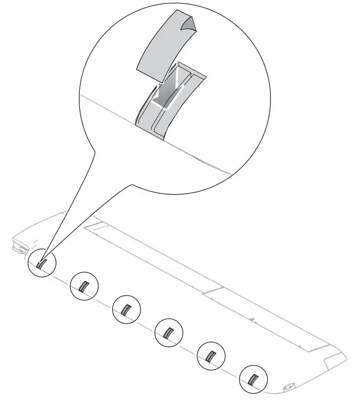
With Slats
- Carefully remove all the foam slat pocket covers (A) from the wing.
- When the pocket is exposed, carefully apply medium CA to each slat pocket.
- Mount the slat onto the wing with the rounded edge facing forward. Ensure that the left and right slats are on the correct wing half. The slat and wing halves are labeled with “L” and “R” indicators.
Without Slats
- Locate the rectangular decals on the decal sheet
- Apply the decals over the slat mounting locations.
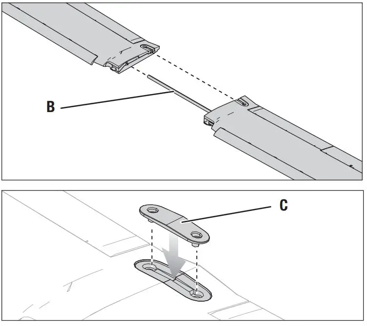
Wing Installation
- Insert the wing joiner tube (B) and slide the left and right wing halves together, as shown.
- Secure the wing together using the wing bracket (C).
Model Assembly (continued)
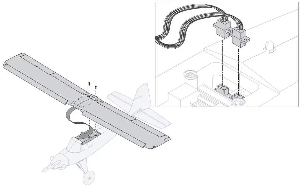
Wing Installation (continued)
3. Insert the connectors from the wings into the sockets on the fuselage.
4. Insert the leading edge of the wing into the wing saddle, and then tighten the M6 x 30mm nylon wing screws to secure the wing in place.
![]() CAUTION: DO NOT crush or otherwise damage the wiring when attaching the wing to the fuselage.
CAUTION: DO NOT crush or otherwise damage the wiring when attaching the wing to the fuselage.
Battery Installation and ESC Arming
The Spektrum™ Smart 3200mAh 4S 30C Li-Po battery (SPMX32004S30) is recommended for best performance. Refer to the Optional Parts List for other recommended batteries. If using a battery other than those listed, the battery should be within the range of capacity, dimensions and weight of the Spektrum Li-Po battery pack to fit in the fuselage. Be sure the model balances at the recommended CG before flying.
![]() WARNING: Always keep hands away from the propeller. When armed, the motor will turn the propeller in response to any throttle movement. If your transmitter supports it, always engage throttle cut before approaching the aircraft any time a battery is connected.
WARNING: Always keep hands away from the propeller. When armed, the motor will turn the propeller in response to any throttle movement. If your transmitter supports it, always engage throttle cut before approaching the aircraft any time a battery is connected.
- Lower the throttle and throttle trim to the lowest settings. Power on the transmitter, then wait 5 seconds.
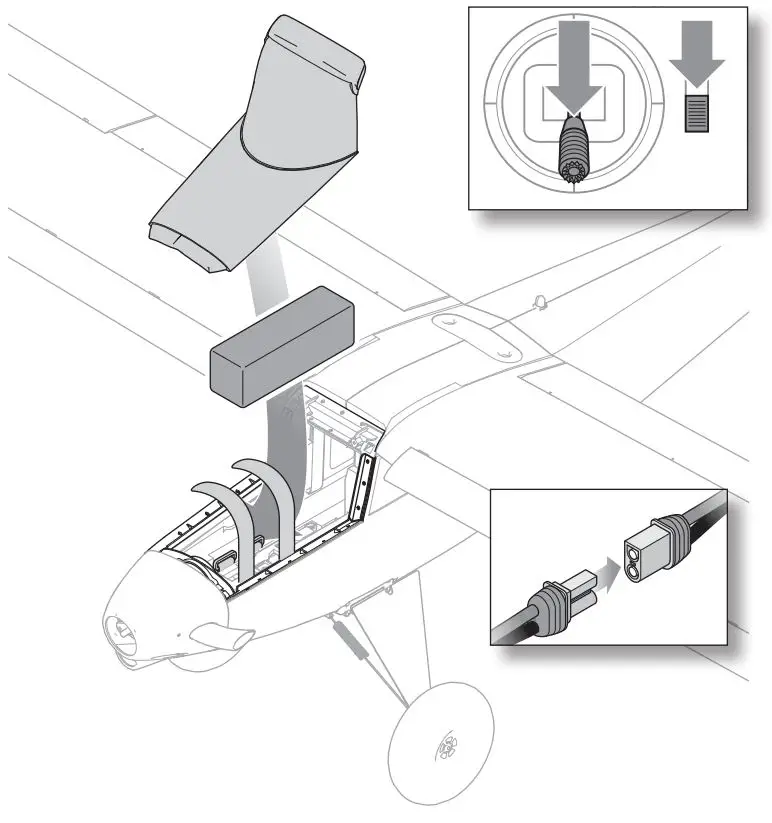
- Lift up on the rear of the hatch up to remove the hatch from the fuselage.
- Install the fully charged battery in the battery compartment, as shown. Secure using the two included hook and loop straps.
- Connect the battery to the ESC (the ESC is now armed).
- Keep the aircraft immobile and away from wind or the system will not initialize.
• The ESC will sound a series of tones.
• An LED will light on the receiver.
• If the ESC sounds a continuous double beep after the flight battery is connected, recharge or replace the battery. - Reinstall the canopy hatch.
Integrated ESC Telemetry
BNF: This aircraft includes telemetry between the ESC and receiver, which can provide information including RPM, voltage, motor current, throttle setting (%), and FET (speed controller) temperature.
PNP: The ESC in this aircraft is capable of delivering telemetry information over the throttle connection when paired with a Smart compatible Spektrum telemetry receiver. It will function with a normal PWM servo signal for common radio control systems.
For more information about compatible transmitters, firmware updates, and how to use the telemetry technology on your transmitter, visit www.SpektrumRC.com.
SAFE® Select Switch Designation BNF
Once SAFE Select is enabled, you can choose to fly in SAFE mode full-time, or assign a switch. Any switch on any channel between 5 and 9 can be used on your transmitter. If the aircraft is bound with SAFE Select disabled, the aircraft will be in AS3X mode exclusively.
![]() CAUTION: Keep all body parts well clear of the propeller and keep the aircraft securely restrained in case of accidental throttle activation.
CAUTION: Keep all body parts well clear of the propeller and keep the aircraft securely restrained in case of accidental throttle activation.
IMPORTANT: To be able to assign a switch, first verify:
- The aircraft was bound with SAFE Select enabled.
- Your choice for the SAFE Select switch is assigned to a channel between 5 and 9 (Gear, Aux1-4), and travel is set at 100% in each direction.
- The aileron, elevator, rudder and throttle direction are set to normal, not reverse.
- The aileron, elevator, rudder and throttle are set to 100% travel. If dual rates are in use, the switches need to be in the 100% position. See your transmitter manual for more information about assigning a switch to a channel.
Assigning a Switch with Stick Inputs
- Power on the transmitter.
- Power on the aircraft.
- Hold both transmitter sticks to the inside bottom corners, and toggle the desired switch 5 times quickly (1 toggle = full up and down).
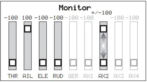
![]()
TIP: Use the channel monitor to verify channel movement.*
* This example of the channel monitor shows the stick positions for assigning a switch, the switch selection on Aux2, and +/- 100% travel on the switch.
4. The control surfaces of the aircraft will move, indicating the switch has been selected.
Repeat the process to assign a different switch or to deactivate the current
Forward Programming
Assign the SAFE Select channel through forward programming on your compatible Spektrum transmitter.
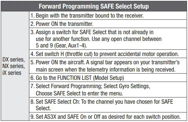
For more information about setting SAFE Select and using Forward Programming, please refer to the following link for a detailed video:
https://www.youtube.com/watch?v=o-46P066cik

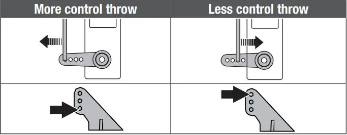
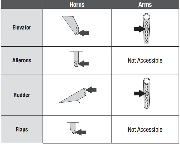
Control Horn and Servo Arm Settings
The table to the right shows the factory settings for the control horns and servo arms. Fly the aircraft at factory settings before making changes.
NOTICE: If control throws are changed from the factory settings, the AR637T gain values may need to be adjusted. Refer to the Spektrum AR637T manual for adjustment of gain values.
After flying, you may choose to adjust the linkage positions for the desired control response. See the table to the right.
Control Surface Direction
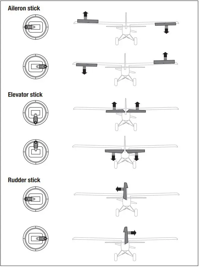
Switch on the transmitter and connect the battery. Use the transmitter to operate the aileron, elevator, and rudder controls. View the aircraft from the rear when checking the control directions.
Ailerons
- Move the aileron stick to the left. The right aileron should move down and the left aileron up, which will cause the aircraft to bank left.
- Move the aileron stick to the right. The right aileron should move up and the left aileron down, which will cause the aircraft to bank right.
Elevators - Pull the elevator stick back. The elevator should move up, which will cause the aircraft to pitch up.
- Push the elevator stick forward. The elevator should move down, which will cause the aircraft to pitch down.
Rudder - Move the rudder stick to the left. The rudder should move to the left, which will cause the aircraft to yaw left.
- Move the rudder stick to the right. The rudder should move to the right, which will cause the aircraft to yaw right.
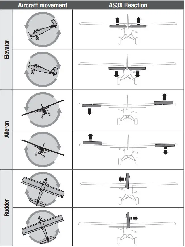
AS3X® Control Response Test BNF
![]() WARNING: Do not perform any testing or maintenance with the propeller installed on the aircraft. Serious injury or property damage could result from the motor starting inadvertently.
WARNING: Do not perform any testing or maintenance with the propeller installed on the aircraft. Serious injury or property damage could result from the motor starting inadvertently.
This test ensures that the AS3X control system is functioning properly. Assemble the aircraft and bind your transmitter to the receiver before performing this test.
1. Raise the throttle just above 25%, then lower the throttle to activate AS3X technology.
![]() WARNING: Keep all body parts, hair and loose clothing away from spinning motor, as these items could become entangled.
WARNING: Keep all body parts, hair and loose clothing away from spinning motor, as these items could become entangled.
2. Move the entire aircraft as shown and ensure the control surfaces move in the direction indicated in the graphic. If the control surfaces do not respond as shown, do not fly the aircraft. Refer to the receiver manual for more information.
Once the AS3X system is active, control surfaces may move rapidly. This is normal. AS3X remains active until the battery is disconnected.
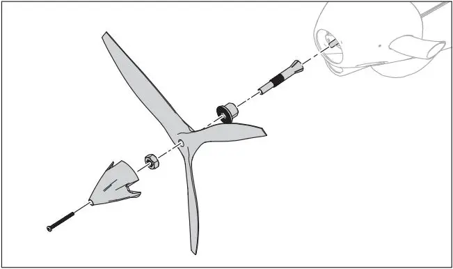
Propeller Installation
![]() WARNING: Do not install the propeller until the aircraft has been completely assembled, all the systems have been checked thoroughly and you are located at a suitable flying site.
WARNING: Do not install the propeller until the aircraft has been completely assembled, all the systems have been checked thoroughly and you are located at a suitable flying site.
![]() WARNING: Never install a cracked, nicked or otherwise damaged propeller or spinner.
WARNING: Never install a cracked, nicked or otherwise damaged propeller or spinner.
NOTICE: If the propeller is not balanced, the aircraft may vibrate, causing the stabilization system to not operate correctly and/or decrease the life of the servos.
- Install the prop adapter and collet.
- Install the propeller, ensuring the embossed size numbers are facing forward.
- Install the nut. Do not overtighten the prop nut as damage to the propeller or threads may result.
- Install the spinner and secure it in place with the included M3 x 8mm machine screw. Ensure the propeller blades are centered in the spinner cutouts. Allowing the spinner to contact the propeller may cause damage to the propeller and may lead to failure of the propeller.
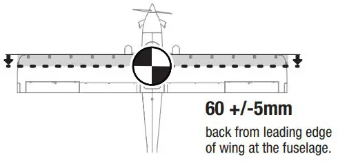
Center of Gravity (CG)
The CG location is measured from the leading edge of the wing at the root. (without slats installed) 60mm +/-5mm back from the leading edge
NOTICE: Install the battery and hatch but do not arm the ESC while checking the CG. Personal injury may result.
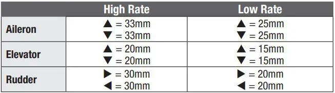
Dual Rates and Control Throws
Program your transmitter to set the rates and control throws to the values given. These values have been tested and are a good starting point to achieve successful flight.
After flying, you may choose to adjust the values for the desired control response.
Consult local laws and ordinances before choosing a flying location.
Range Check your Radio System
Before you fly, range check the radio system. Refer to your specific transmitter instruction manual for range test information.
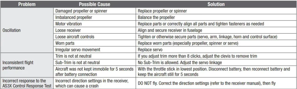
Oscillation
Once the AS3X system is active (after advancing the throttle for the first time), you will normally see the control surfaces react to aircraft movement. In some flight conditions you may see oscillation (the aircraft rocks back and forth on one axis due to overcontrol). If oscillation occurs, refer to the Troubleshooting Guide for more information.
Takeoff
Place the aircraft facing into the wind. Set your transmitter in low rate and use your flaps switch to drop the flaps to takeoff or “half position”. Gradually increase the throttle to ¾ and steer with the rudder. Flaps make takeoffs shorter. As the tail comes off the ground, pull back gently on the elevator. Climb to a comfortable altitude and then flip your flaps switch to level the flaps.
Flying
For your first flights with the recommended battery pack (SPMX32004S30), set your transmitter timer or a stopwatch to 4 minutes, land the aircraft. Adjust your timer for longer or shorter flights once you have flown the model. If at any time the motor power reduces, land the aircraft immediately to recharge the flight battery. See the Low Voltage Cutoff (LVC) section for more details on maximizing battery health and run time.
Landing
Land the aircraft into the wind. Use high rate Elevator for landings. Use a small amount of throttle for the entire descent. Lower the throttle to ¼ and select your flap switch to deploy the flaps to the landing, or full down position. Flaps will make the landing approach steeper and slower, and allow for a smoother landing. This will slow the aircraft further. Keep the throttle on until the aircraft is ready to flare. During flare, keep the wings level and the aircraft pointed into the wind. Gently lower the throttle while pulling back on the elevator to bring the aircraft down on its wheels.
If landing on grass, it is best to hold full up elevator after touchdown and when taxiing to prevent nosing over. Once on the ground, avoid sharp turns until the plane has slowed enough to prevent scraping the wingtips.
NOTICE: If a crash is imminent, reduce the throttle and trim fully. Failure to do so could result in extra damage to the airframe, as well as damage to the ESC and motor.
NOTICE: After any impact, always ensure the receiver is secure in the fuselage. If you replace the receiver, install the new receiver in the same orientation as the original receiver or damage may result.
NOTICE: Crash damage is not covered under warranty.
NOTICE: When you are finished flying, never leave the aircraft in direct sunlight or in a hot, enclosed area such as a car. Doing so can damage the aircraft.
Low Voltage Cutoff (LVC)
When a Li-Po battery is discharged below 3V per cell, it will not hold a charge. The ESC protects the flight battery from over-discharge using Low Voltage Cutoff (LVC). Before the battery charge decreases too much, LVC removes power supplied to the motor. Power to the motor reduces, showing that some battery power is reserved for flight control and safe landing. Disconnect and remove the Li-Po battery from the aircraft after use to prevent trickle discharge. Charge your Li-Po battery to about half capacity before storage. During storage, make sure the battery charge does not fall below 3V per cell. LVC does not prevent the battery from over-discharge during storage.
NOTICE: Repeated flying to LVC will damage the battery.
TIP: Monitor your aircraft battery’s voltage before and after flying by using a Li-Po Cell Voltage Checker (SPMXBC100, sold separately).
Repairs
Thanks to the EPO material in this aircraft, repairs to the foam can be made using virtually any adhesive (hot glue, regular CA, epoxy, etc). When parts are not repairable, see the Replacement Parts List for ordering by item number. For a listing of all replacement and optional parts, refer to the list at the end of this manual.
NOTICE: Use of CA accelerant on your aircraft can damage paint. DO NOT handle the aircraft until accelerant fully dries.
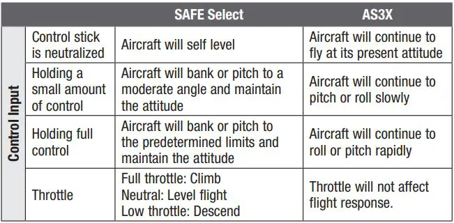
SAFE Select Flying Tips BNF
When flying in SAFE Select mode the aircraft will return to level flight any time the aileron and elevator controls are at neutral. Applying aileron or elevator control will cause the airplane to bank, climb or dive. The amount the stick is moved will determine the attitude the airplane flies. Holding full control will push the aircraft to the pre-determined bank and roll limits, but it will not go past those angles.
When flying with SAFE Select, it is normal to hold the control stick deflected with moderate aileron input when flying through a turn. To fly smoothly with SAFE Select, avoid making frequent control changes and don’t attempt to correct for minor deviations. Holding deliberate control inputs will command the aircraft to fly at a specific angle, and the model will make all corrections to maintain that flight attitude.
When flying with SAFE Select, throttle will make the aircraft climb or descend. Full throttle will cause the aircraft to pitch up and climb slightly. Mid throttle will keep the airplane flying level. Low throttle will cause the airplane to descend slightly nose-down. Return the elevator and aileron controls to neutral before switching from SAFE Select mode to AS3X mode. If you do not neutralize controls when switching into AS3X mode, the control inputs used for SAFE Select mode will be excessive for AS3X mode and the aircraft will react immediately.
Differences between SAFE Select and AS3X modes
This section is generally accurate but does not take into account flight speed, battery charge status, and other limiting factors.
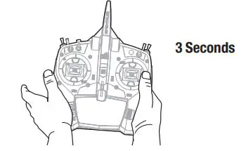
In Flight Trimming BNF
During your first flight, trim the aircraft for level flight at 3/4 throttle with flaps up. Make small trim adjustments with your transmitter’s trim switches to straighten the aircraft’s flight path. After adjusting the trim, do not touch the control sticks for 3 seconds. This allows the receiver to learn the correct settings to optimize AS3X performance. Failure to do so could affect flight performance.
Post Flight
- Disconnect the flight battery from the ESC (Required for safety and battery life).
- Power OFF the transmitter.
- Remove the flight battery from the aircraft.
- Recharge the flight battery.
- Repair or replace all damaged parts.
- Store the flight battery apart from the aircraft and monitor the battery charge.
- Make note of the flight conditions and flight plan results, planning for future flights.
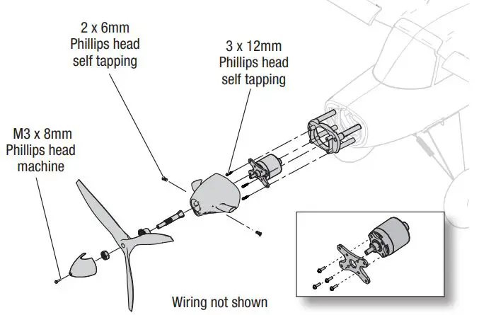
Motor Service
![]() CAUTION: Always disconnect the flight battery before performing motor service.
CAUTION: Always disconnect the flight battery before performing motor service.
Disassembly
- Remove the spinner screw and spinner from the propeller shaft.
- Remove the spinner nut by using an adjustable wrench.
- Remove the propeller, back hub and the propeller shaft from the motor shaft.
- Remove the two screws from the sides of the cowling and remove the cowling from the fuselage.
- Remove the four screws and the motor with the X-mount from the fuselage.
- Disconnect the motor wires from the ESC wires.
- Remove the four M3 x 6mm Phillips head machine screws and motor from the X-mount.
Assembly
- Assemble in reverse order.
- Correctly align and connect the motor wire colors with the ESC wires.
- Install the propeller with the paint facing out from the motor.
- Tighten the spinner nut to secure the propeller into place.
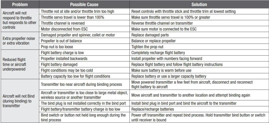
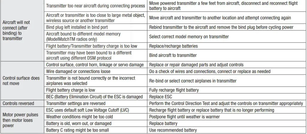
Troubleshooting Guide AS3X BNF
Troubleshooting Guide
Float Installation (Optional)
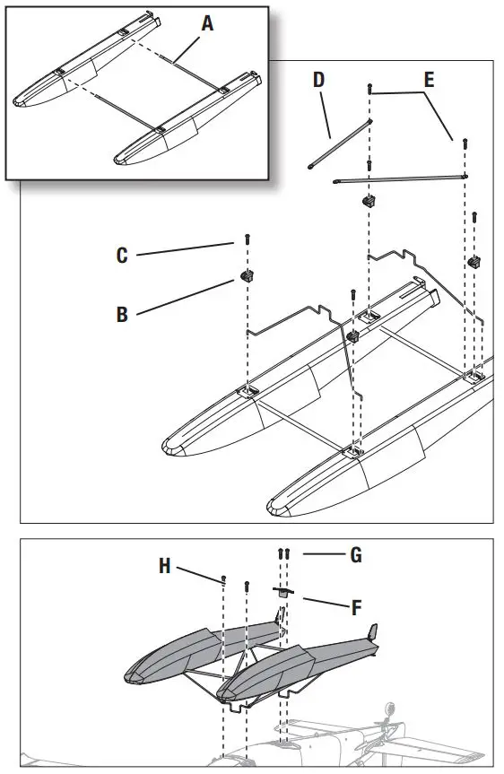
Float Assembly
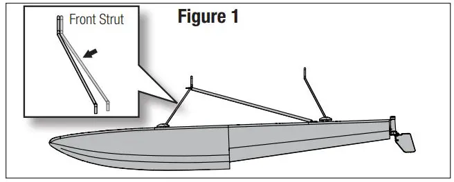
- Install the 2 cross members (A) to the left and right floats as shown.
- Install the front and rear float struts to the floats and secure the assembly together using the included 4 float plates (B) and M2.5 x 25mm machine screws (C). The front strut has slightly more of an angle than the rear strut (Figure 1).
- Install the front support members (D) as shown using the included self tapping screws (E).
Float Assembly Installation
- Align and mount the float set assembly to the bottom of the fuselage.
- Secure the back section of the floats to the fuselage using the included bracket (F) and two 3mm x 10mm self tapping screws (G).
- Secure the front section of the floats using the two included 3mm x 10mm self tapping screws (H) to secure the front support members to the bottom of the fuselage.
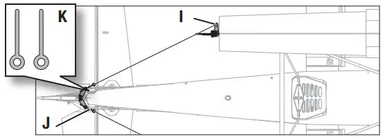
- Attach the included wires from each float rudder (I) to the quick connectors in the pull pull horn (J) using the two included pins (K) and (2) M2.5 x 4mm machine screws.
Disassemble in reverse order.
Flying Off Water
Flying off water poses a higher risk because piloting errors or water conditions can cause the aircraft to become stranded. Only fly from the water when a level of comfort has been achieved flying the aircraft from the ground.
Pre-Flight
Ensure the optional floats are secure on the fuselage and the water rudders are correctly connected and operating with the main rudder before putting the aircraft in the water. Select an area to fly that does not have water currents, salt water, or debris. Look around the flight area and be aware of trees, docks, buoys, or other obstacles. Always fly with a spotter and avoid swimmers, boaters, people fishing, and people on the beach.
Taxiing
When taxiing, use low throttle settings and the rudders to steer. Hold up elevator to help keep the rudders in the water and the nose of the floats above the surface. Steer into the wind when turning, and crab into the wind if crosswind taxiing is required. When turning or crabbing into the wind, apply aileron against the wind to keep the upwind side of the wing down and prevent the aircraft from being flipped over. Do not apply down elevator when the airplane is taxiing or during the takeoff run.
On Step
When speed increases with throttle, the floats will rise out of the water and begin to plane on the surface of the water, riding “on step.” The floats will come on step at a speed below flight speed, this is a transitional phase when the aircraft is not up to flight speed yet. This is considered a high speed taxi. Do not attempt to take off as soon as the aircraft comes on step. Use low to medium throttle and hold up elevator to manage speed on the water during a high speed taxi.
Takeoff
To lift off from the water, set the flaps to the takeoff position, hold up elevator and accelerate the aircraft to bring it on step. Relax the up elevator as the airplane comes on step and accelerate to flight speed with full throttle. When the aircraft is travelling at a sufficient speed, pull back slightly on the elevator to rotate for liftoff.
Landing
To land on the water, set the flaps to the landing position, and fly into the wind. Reduce the throttle to a low setting but keep some power during the approach. As the aircraft settles into ground effect, reduce the throttle fully and hold up elevator to flare. Hold up elevator through the touch down and as the airplane decelerates on the water.
![]() WARNING: Never attempt to retrieve a downed aircraft by swimming unless you are sufficiently trained and/or there is another person available to respond in the case of an emergency.
WARNING: Never attempt to retrieve a downed aircraft by swimming unless you are sufficiently trained and/or there is another person available to respond in the case of an emergency.
![]() CAUTION: Have a plan for retrieval in the event the airplane becomes stranded. Never retrieve a downed model in the water alone.
CAUTION: Have a plan for retrieval in the event the airplane becomes stranded. Never retrieve a downed model in the water alone.
![]() CAUTION: If at any time water splashes in the fuselage while flying from water, bring the airplane to shore, open the battery hatch and immediately remove any water that may have gotten in the fuselage. Leave the battery hatch open overnight to let the inside dry out and to prevent moisture damage to the electronic components. Failure to do so could cause the electronic components to fail, which could result in a crash.
CAUTION: If at any time water splashes in the fuselage while flying from water, bring the airplane to shore, open the battery hatch and immediately remove any water that may have gotten in the fuselage. Leave the battery hatch open overnight to let the inside dry out and to prevent moisture damage to the electronic components. Failure to do so could cause the electronic components to fail, which could result in a crash.
TIP: Use a fishing pole with heavy line as a retrieval tool. Attach a tennis ball to the line, and throw the ball past a stranded aircraft to retrieve it.
Thrust Reversing (Optional)
The Avian™ Smart ESC in this aircraft is equipped with thrust reversing, but it must be enabled before it will function. Reversing the motor can be helpful when taxiing or for shortening ground roll after a landing. Flipping the designated switch reverses motor rotation, throttle will still control motor speed.
![]() WARNING: Never attempt to use thrust reversing in flight. Applying reverse thrust while in flight will result in loss of control and possibly a crash. Crash damage is not covered under warranty.
WARNING: Never attempt to use thrust reversing in flight. Applying reverse thrust while in flight will result in loss of control and possibly a crash. Crash damage is not covered under warranty.
IMPORTANT: The motor will draw more current in reverse as the propeller becomes less efficient and creates more drag. This can reduce flight time.
IMPORTANT: Thrust reversing requires a Spektrum receiver with Smart Throttle (including the AR637TA and AR631) and a Spektrum transmitter with a minimum of 7 channels. The Avian ESC is also backwards compatible with conventional receivers (PWM output signal) for normal operation, but reversing functions are only available with Smart Throttle technology.
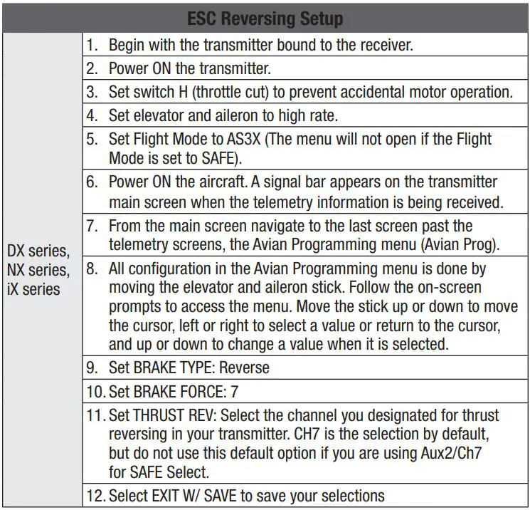
Thrust Reversing Setup
Transmitter
On the transmitter, select an open channel (not already in use), and assign it to an open switch. Use a different channel for thrust reversing and SAFE Select. Motor reversing is assigned to Aux 2/Channel 7, by default, in the Smart ESC. If SAFE Select and the ESC are assigned to the same channel, the motor will reverse in flight.
![]() WARNING: Do not assign thrust reversing and SAFE Select to the same channel. Doing so will reverse the motor when SAFE Select is enabled during flight, resulting in a crash.
WARNING: Do not assign thrust reversing and SAFE Select to the same channel. Doing so will reverse the motor when SAFE Select is enabled during flight, resulting in a crash.
ESC
Set up the transmitter according to the setup chart, and bind your transmitter to the airplane. The airplane must be powered on and bound to the transmitter to access the Smart ESC programming.
As an alternative, it is possible to program the ESC with the Smart ESC Programming Box (SPMXCA200, optional, not included).
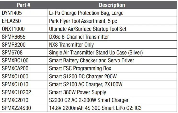
Replacement Parts

Recommended Items
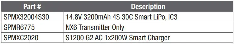
Optional Items
AMA National Model Aircraft Safety Code
Effective January 1, 2018
A model aircraft is a non-human-carrying device capable of sustained flight within visual line of sight of the pilot or spotter(s). It may not exceed limitations of this code and is intended exclusively for sport, recreation, education and/or competition. All model flights must be conducted in accordance with this safety code and related AMA guidelines, any additional rules specific to the flying site, as well as all applicable laws and regulations.
As an AMA member I agree:
- I will not fly a model aircraft in a careless or reckless manner.
- I will only fly models weighing more than 55 pounds, including fuel, if certified
- I will not interfere with and will yield the right of way to all human-carrying through AMA’s Large Model Airplane Program. aircraft using AMA’s See and Avoid Guidance and a spotter when appropriate.
- I will only fly a turbine-powered model aircraft in compliance with AMA’s Gas
- I will not operate any model aircraft while I am under the influence of alcohol or Turbine Program. any drug that could adversely affect my ability to safely control the model.
- I will not fly a powered model outdoors closer than 25 feet to any individual,
- I will avoid flying directly over unprotected people, moving vehicles, and occupied structures. except for myself or my helper(s) located at the flighting, unless I am taking off and landing, or as otherwise provided in AMA’s Competition Regulation.
- I will fly Free Flight (FF) and Control Line (CL) models in compliance with AMA’s safety programming.
- I will use an established safety line to separate all model aircraft operations from spectators and bystanders.
- I will maintain visual contact of an RC model aircraft without enhancement other than corrective lenses prescribed to me. When using an advanced flight system, such as an autopilot, or flying First-Person View (FPV), I will comply with AMA’s Advanced Flight System programming.
Limited Warranty
What this Warranty Covers
Horizon Hobby, LLC, (Horizon) warrants to the original purchaser that the product purchased (the “Product”) will be free from defects in materials and workmanship at the date of purchase.
What is Not Covered
This warranty is not transferable and does not cover (i) cosmetic damage, (ii) damage due to acts of God, accident, misuse, abuse, negligence, commercial use, or due to improper use, installation, operation or maintenance, (iii) modification of or to any part of the Product, (iv) attempted service by anyone other than a Horizon Hobby authorized service center, (v) Product not purchased from an authorized Horizon dealer, or (vi) Product not compliant with applicable technical regulations, or (vii) use that violates any applicable laws, rules, or regulations. OTHER THAN THE EXPRESS WARRANTY ABOVE, HORIZON MAKES NO OTHER WARRANTY OR REPRESENTATION, AND HEREBY DISCLAIMS ANY AND ALL IMPLIED WARRANTIES, INCLUDING, WITHOUT LIMITATION, THE IMPLIED WARRANTIES OF NON-INFRINGEMENT, MERCHANTABILITY AND FITNESS FOR A PARTICULAR PURPOSE. THE PURCHASER ACKNOWLEDGES THAT THEY ALONE HAVE DETERMINED THAT THE PRODUCT WILL SUITABLY MEET THE REQUIREMENTS OF THE PURCHASER’S INTENDED USE.
Purchaser’s Remedy
Horizon’s sole obligation and purchaser’s sole and exclusive remedy shall be that Horizon will, at its option, either (i) service, or (ii) replace, any Product determined by Horizon to be defective. Horizon reserves the right to inspect any and all Product(s) involved in a warranty claim. Service or replacement decisions are at the sole discretion of Horizon. Proof of purchase is required for all warranty claims. SERVICE OR REPLACEMENT AS PROVIDED UNDER THIS WARRANTY IS THE PURCHASER’S SOLE AND EXCLUSIVE REMEDY.
Limitation of Liability
HORIZON SHALL NOT BE LIABLE FOR SPECIAL, INDIRECT, INCIDENTAL OR CONSEQUENTIAL DAMAGES, LOSS OF PROFITS OR PRODUCTION OR COMMERCIAL LOSS IN ANY WAY, REGARDLESS OF WHETHER SUCH CLAIM IS BASED IN CONTRACT, WARRANTY, TORT, NEGLIGENCE, STRICT LIABILITY OR ANY OTHER THEORY OF LIABILITY, EVEN IF HORIZON HAS BEEN ADVISED OF THE POSSIBILITY OF SUCH DAMAGES. Further, in no event shall the liability of Horizon exceed the individual price of the Product on which liability is asserted. As Horizon has no control over use, setup, final assembly, modification or misuse, no liability shall be assumed nor accepted for any resulting damage or injury. By the act of use, setup or assembly, the user accepts all resulting liability. If you as the purchaser or user are not prepared to accept the liability associated with the use of the Product, purchaser is advised to return the Product immediately in new and unused condition to the place of purchase.
Law
These terms are governed by Illinois law (without regard to conflict of law principals). This warranty gives you specific legal rights, and you may also have other rights which vary from state to state. Horizon reserves the right to change or modify this warranty at any time without notice.
WARRANTY SERVICES
Questions, Assistance, and Services
Your local hobby store and/or place of purchase cannot provide warranty support or service. Once assembly, setup or use of the Product has been started, you must contact your local distributor or Horizon directly. This will enable Horizon to better answer your questions and service you in the event that you may need any assistance.
For questions or assistance, please visit our website at www.horizonhobby.com, submit a Product Support Inquiry, or call the toll free telephone number referenced in the Warranty and Service Contact Information section to speak with a Product Support representative.
Inspection or Services
If this Product needs to be inspected or serviced and is compliant in the country you live and use the Product in, please use the Horizon Online Service Request submission process found on our website or call Horizon to obtain a Return Merchandise Authorization (RMA) number. Pack the Product securely using a shipping carton. Please note that original boxes may be included, but are not designed to withstand the rigors of shipping without additional protection. Ship via a carrier that provides tracking and insurance for lost or damaged parcels, as Horizon is not responsible for merchandise until it arrives and is accepted at our facility. An Online Service Request is available at http://www.horizonhobby.com/content/service-center_render-servicecenter. If you do not have internet access, please contact Horizon Product Support to obtain a RMA number along with instructions for submitting your product for service. When calling Horizon, you will be asked to provide your complete name, street address, email address and phone number where you can be reached during business hours. When sending product into Horizon, please include your RMA number, a list of the included items, and a brief summary of the problem. A copy of your original sales receipt must be included for warranty consideration. Be sure your name, address, and RMA number are clearly written on the outside of the shipping carton.
NOTICE: Do not ship LiPo batteries to Horizon. If you have any issue with a LiPo battery, please contact the appropriate Horizon Product Support office.
Warranty Requirements
For Warranty consideration, you must include your original sales receipt verifying the proof-of-purchase date. Provided warranty conditions have been met, your Product will be serviced or replaced free of charge. Service or replacement decisions are at the sole discretion of Horizon.
Non-Warranty Service
Should your service not be covered by warranty, service will be completed and payment will be required without notification or estimate of the expense unless the expense exceeds 50% of the retail purchase cost. By submitting the item for service you are agreeing to payment of the service without notification. Service estimates are available upon request. You must include this request with your item submitted for service. Non-warranty service estimates will be billed a minimum of ½ hour of labor. In addition you will be billed for return freight. Horizon accepts money orders and cashier’s checks, as well as Visa, MasterCard, American Express, and Discover cards. By submitting any item to Horizon for service, you are agreeing to Horizon’s Terms and Conditions found on our website http://www.horizonhobby.com/content/service-center_render-service-center.
ATTENTION: Horizon service is limited to Product compliant in the country of use and ownership. If received, a non-compliant Product will not be serviced. Further, the sender will be responsible for arranging return shipment of the un-serviced Product, through a carrier of the sender’s choice and at the sender’s expense. Horizon will hold non-compliant Product for a period of 60 days from notification, after which it will be discarded.
Contact Information

FCC Information
FCC ID: BRWTIARLGTNG1
This equipment complies with FCC and IC radiation exposure limits set forth for an uncontrolled environment. This equipment should be installed and operated with minimum distance 20cm between the radiator and/or antenna and your body (excluding fingers, hands, wrists, ankles and feet). This transmitter must not be collocated or operating in conjunction with any other antenna or transmitter.
Supplier’s Declaration of Conformity
Turbo Timber Evolution (EFL105250/EFL105275)
![]() This device complies with part 15 of the FCC Rules. Operation is subject to the following two conditions: (1) This device may not cause harmful interference, and (2) this device must accept any interference received, including interference that may cause undesired operation.
This device complies with part 15 of the FCC Rules. Operation is subject to the following two conditions: (1) This device may not cause harmful interference, and (2) this device must accept any interference received, including interference that may cause undesired operation.
![]() CAUTION: Changes or modifications not expressly approved by the party responsible for compliance could void the user’s authority to operate the equipment.
CAUTION: Changes or modifications not expressly approved by the party responsible for compliance could void the user’s authority to operate the equipment.
NOTE: This equipment has been tested and found to comply with the limits for a Class B digital device, pursuant to part 15 of the FCC Rules. These limits are designed to provide reasonable protection against harmful interference in a residential installation. This equipment generates, uses and can radiate radio frequency energy and, if not installed and used in accordance with the instructions, may cause harmful interference to radio communications. However, there is no guarantee that interference will not occur in a particular installation. If this equipment does cause harmful interference to radio or television reception, which can be determined by turning the equipment off and on, the user is encouraged to try to correct the interference by one or more of the following measures:
- Reorient or relocate the receiving antenna.
- Increase the separation between the equipment and receiver.
- Connect the equipment into an outlet on a circuit different from that to which the receiver is connected.
- Consult the dealer or an experienced radio/TV technician for help.
Horizon Hobby, LLC
2904 Research Rd.,
Champaign, IL 61822
Email: [email protected]
Web: HorizonHobby.com
IC Information
IC: 6157A-TIARLGTNG1
CAN ICES-3 (B)/NMB-3(B)
This device contains license-exempt transmitter(s)/receivers(s) that comply with Innovation, Science, and Economic Development Canada’s license-exempt RSS(s). Operation is subject to the following 2 conditions:
- This device may not cause interference.
- This device must accept any interference, including interference that may cause undesired operation of the device.
Compliance Information for the European Union
![]() EU Compliance Statement:
EU Compliance Statement:
Turbo Timber Evolution PNP (EFL105275); Hereby, Horizon Hobby,
LLC declares that the device is in compliance with the following: EU EMC Directive 2014/30/EU; RoHS 2 Directive 2011/65/EU; RoHS 3 Directive – Amending 2011/65/EU Annex II 2015/863.
Turbo Timber Evolution BNF Basic (EFL105250); Hereby, Horizon Hobby, LLC declares that the device is in compliance with the following: EU Radio Equipment Directive 2014/53/EU; RoHS 2 Directive 2011/65/EU; RoHS 3 Directive – Amending 2011/65/EU Annex II 2015/863.
Wireless Frequency Range and Wireless Output Power: Receiver: 2402-2478MHz / 19.95dBm
The full text of the EU declaration of conformity is available at the following internet address: https://www.horizonhobby.com/content/support-render-compliance.
EU Manufacturer of Record:
Horizon Hobby, LLC
2904 Research Road
Champaign, IL 61822 USA
EU Importer of Record:
Horizon Hobby, GmbH
Hanskampring 9
22885 Barsbüttel Germany
WEEE NOTICE: This appliance is labeled in accordance with European ![]() Directive 2012/19/EU concerning waste of electrical and electronic equipment (WEEE). This label indicates that this product should not be disposed of with household waste. It should be deposited at an appropriate facility to enable recovery and recycling.
Directive 2012/19/EU concerning waste of electrical and electronic equipment (WEEE). This label indicates that this product should not be disposed of with household waste. It should be deposited at an appropriate facility to enable recovery and recycling.
![]()
![]()
© 2021 Horizon Hobby, LLC.
E-flite, Avian, DSM, DSM2, DSMX, Bind-N-Fly, BNF, the BNF logo, Plug-N-Play, AS3X, SAFE, the SAFE logo, Model Match, IC3, EC3, and the
Horizon Hobby logo are trademarks or registered trademarks of Horizon Hobby, LLC. The Spektrum trademark is used with permission of Bachmann Industries, Inc.
All other trademarks, service marks and logos are property of their respective owners. US 8,672,726. US 9,056,667. US 9,753,457. US 9,930,567. US 10,078,329. US 10,419,970. US 10,849,013. Other patents pending.
https://www.horizonhobby.com/content/e-flite-rc
Updated 6/21 EFL105250, EFL105275 30327.1