
![]()
E470 Series 3 SMETS2 100mm
User manual and
functional description: Issue 1.3

Electricity Meters BS/IEC/MID ZCX310
Safety
1.1 Safety information
The following symbols are used to draw your attention to the relevant danger level, i.e. the severity and probability of any danger, in the individual sections of this document.
![]() Danger
Danger
This symbol is used to indicate a possibly dangerous situation that could result in severe physical injury or death.
![]() Warning
Warning
This symbol is used to indicate a possibly dangerous situation that could result in minor physical injury or material damage.
![]() Note
Note
This symbol is used to indicate general details and other useful information.
In addition to the danger level, safety information also describes the type and source of the danger, its possible consequences, and measures for avoiding the danger.
1.2 Meter Operator Code of Practice
The E470 must be installed in accordance with the Meter Operation Code of Practice Agreement (MOCOPA®), defining safety, technical and business interface requirements regarding the provision of meter operation services.
For more information see www.mocopa.org.uk
1.3 Safety regulations
The following safety regulations must be observed at all times:
- Local safety regulations must be observed and shall take precedence over these regulations in the event of a conflict. Only technically qualified and appropriately trained personnel are authorized to install the meters.
- Meters that have been dropped must not be installed, even if no damage is apparent, but must be returned to the service and repair department (or the manufacturer) for testing. Internal damage may result in malfunctions or short-circuits.
- The meters must not be cleaned under running water or with compressed air. Water ingress can cause short-circuits.
- The meter terminal cover should be secured in place before any load is supplied.
Physical description
2.1 Meter construction
This document doesn’t include a description of the internal construction of the meter. Opening the meter after delivery isn’t permitted. If it is opened the meter’s calibration and certification will automatically be rendered void.
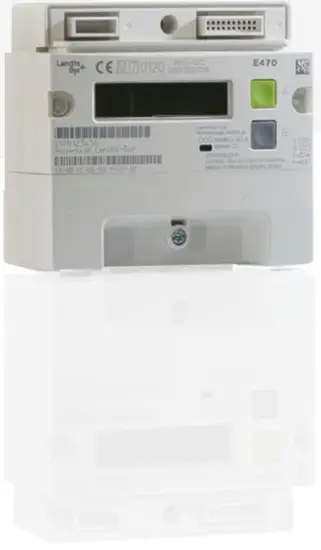
The meter case is made of antistatic polycarbonate plastic glass filled 10%.
The top part of the meter houses an intimate communications hub interface (ICHI).
The middle part of the meter – the meter faceplate area – comprises the user interface with the liquid crystal display (LCD), the metrology (measurement) light-emitting diode
(LED) and the display buttons A and B.
The lower part of the meter – the terminal area – is protected by a removable terminal cover. It includes the main electricity ingress and egress terminals and auxiliary connections.
Figure 1: Front view of the meter
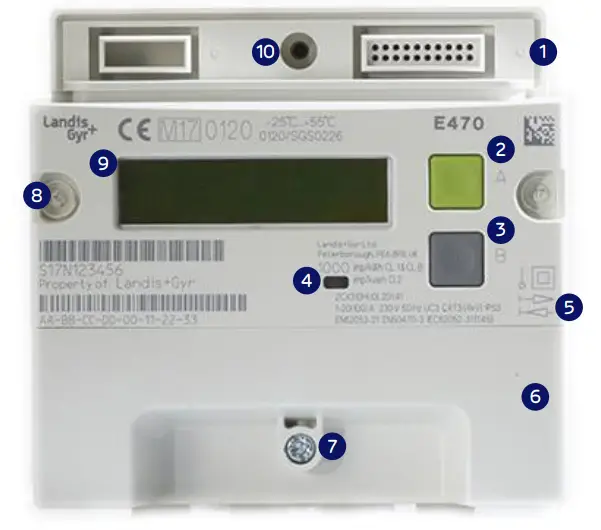
| 1. Intimate communications hub interface (ICHI) | 6. Terminal cover |
| 2. Display button A | 7. Terminal cover sealing point: wire rope and ferrule |
| 3. Display button B | 8. Meter se ing (left and right side): ultrasonic stakes printed with the manufacturer’s name (L+G) and the year of manufacture |
| 4. Metrology LED (red) | 9. Liquid Crystal Display (LCD) |
| 5. Faceplate: see Figure 4 for details | 10. ICHI sealing: secured by comms hub screw |
Meter displays
3.1 Display and navigation structure
The E470 SMETS2 meter has a display structure that provides end-users with information relating to the meter’s operation.
3.2 Display examples
The following section details the typical displays that the meter supports and includes the following:
- Time/date displays
- Total register displays
- Rate register displays
- Instantaneous value displays
3.2.1 Time/date displays
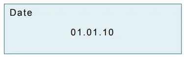
The date is shown in the format DD.MM.YY.

The time is shown in the format HH:MM: SS
3.2.2 Total registers
The following display formats are for total energy registers. The examples show 5 significant figures and no decimal places – just like it’ll appear on the meter display.
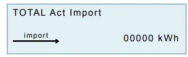
Total active import energy
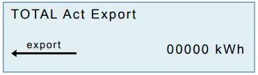
Total active export energy

Total active energy (sum) (import + export)

Total active energy (net) (import-export)
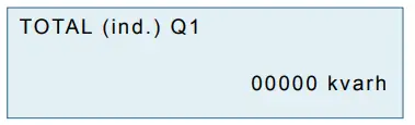
Total reactive energy quadrant 1 (import inductive)

Total reactive energy quadrant 2 (import capacitive)

Total reactive energy quadrant 3 (export inductive)
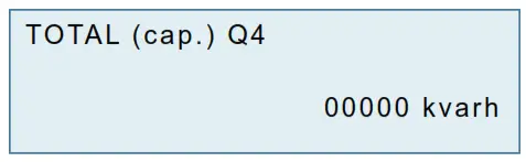
Total reactive energy quadrant 4 (export capacitive)
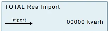
Total reactive import energy (vary)

Total reactive export energy (vary)
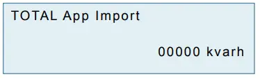
Total apparent import energy (kVah): +VA (QI+QIV)
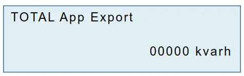
Total apparent export energy (kVah): +VA (QII+QIII)
3.2.3 Rate registers
The meter displays the time of use (TOU) rates and block-rated registers.
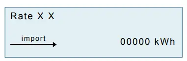
TOU Rate xx – active import energy (kWh) (rates 1 to 48)
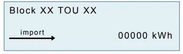
Block xx TOU Rate xx – active import energy (kWh) (Block 01 to 04, TOU Rate 01 to 08)
The import and export representation arrow is for Active energy only
3.2.4 Instantaneous values
The meter displays instantaneous values for power, power factor, voltage, current, frequency, and meter balance.
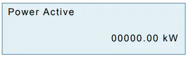
Instantaneous Active Power (kW)

Instantaneous Reactive Power (kvar)
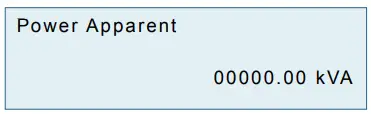
Instantaneous Apparent Power (kVA)
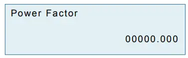
Power Factor
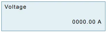
Voltage (V)
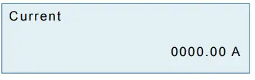
Current (A)
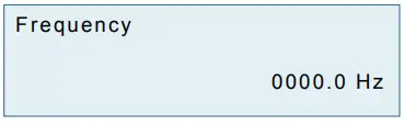
Mains Frequency (Hz)

Meter Balance (Credit Mode)
3.2.5 MID displays
The meter can display the approved and calculated checksums (CRC).

Approved CRC
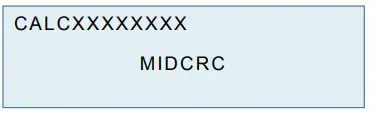
Calculated CRC
3.2.6 Charge displays
The meter can display the standing charge.
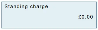
Standing charge (pounds and pence)
3.3 Credit mode status displays
The following section details the displays that the user can see when in the credit mode of operation.
3.3.1 Credit mode balance
Meter in credit mode:
Supply on, credit meter balance is shown.
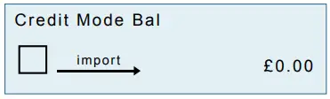
Credit mode balance
3.3.2 Customer PIN-enabled but not entered
Display when customer PIN-enabled but not entered. Supply status could be any one of the following: off, arm, or on.
PIN enabled but not entered
3.3.3 Load limit exceeded
Display when the customer has exceeded load limit. Supply status armed.
When load limit is exceeded the supply control switch box symbol flashes
Debt management displays
The meter supports two types of debt collection: payment-based and time-based (see below).
3.4.1 Payment based debt displays
3.4.1.1 Debt remaining
Where the meter is set up to perform payment-based debt collection, it will display the amount of debt that the customer has outstanding.
 Debt remaining
3.4.1.2 Debt collection percentage
The meter will display the amount of debt to be collected from each top-up performed (detailed as a percentage per payment).
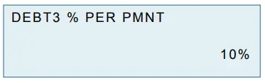
Debt remaining percentage per payment
3.4.1.3 Maximum debt collection per week
The meter will detail the maximum amount of debt that it’s able to collect per week from the payment top-ups received.
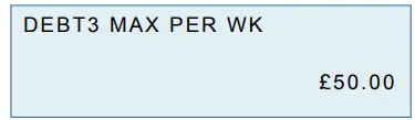
Maximum debt collection per week
3.4.1.4 Debt amount paid
The meter will detail the total amount of debt that’s been paid, based on the payments that the meter has processed.
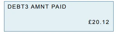
Amount of debt paid
3.4.2 Time-based debt displays
3.4.2.1 Debt remaining
Where the meter is set up to perform time-based debt collection, it will display the amount of debt that the customer has outstanding.
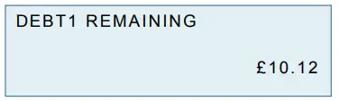
Amount of debt remaining
3.4.2.2 Debt collection interval
The meter will display the amount of debt to be collected, detailing the time period for each collection and the amount of money to be collected at each interval.
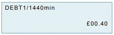
Debt collection period (One hour or one day)
3.4.2.3 Debt collection not configured
The meter will display a ‘not configured’ notification if it hasn’t been set up to collect a time-based debt.
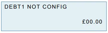
Debt collection not configured
3.4.2.4 Debt amount paid
The meter will detail the total amount of debt paid, based on the payments already processed by the meter.
FAQs
Is the E470 series Smart Meter safe?
Yes. The E470 series Smart Meter is designed and manufactured in accordance with the latest international safety standards, and is also certified by a number of independent testing authorities.
What safety features does the E470 series Smart Meter have?
The E470 series Smart Meter is designed to be safe and reliable. It has a number of safety features built in, including:
• An integrated safety interlock system that prevents the meter from being tampered with while it is in operation.
• A tamper-proof enclosure that protects the meter from physical damage.
• An internal power supply that automatically disconnects if there is a fault or if there is an unsafe voltage applied to the meter. This prevents the possibility of dangerous voltages being applied to external equipment, such as personal computers and television sets.
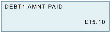
Amount of debt paid
D000058620 en a – E470 Series 3 SMETS2 100 mm – ZCX310 –
User manual and functional description drax.com
Updated on: 24/09/2020
Version:
1.3