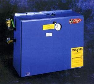
EFM Elec-T-Therm Electric Boiler Installation Manual
Check the unit for shipping damage. If there is any evidence of damage, including damage to the exterior jacket, you should contact your freight company immediately and file a claim. Do not install the boiler.
Proper selection of the right size EB4, or any heating device, requires an accurate heat balance performed by a qualified heating professional. The use of an indirect hot water heater with the EB4 may significantly and adversely affect the satisfactory performance of the EB4. Use of an indirect hot water heater with the EB4 is not recommended. These instructions include options for installation, including system components. Components are not provided, unless specifically noted otherwise. Suggested installation schemes are for the brand names specified. If another brand is used, see the manufacturer’s instructions for installation.
Installation of the efm Elec-T-Therm boiler requires an experienced and trained service person. The EB4 is similar to an oil or gas fired boiler in many ways. The differences are important. Follow the installation instructions carefully to avoid problems. Contact efm if you have any questions or concerns.
Wiring, piping and construction must meet all local, state and federal codes that may apply. In the event that no local electrical codes apply, the National Electrical Code should be followed.
Before you start. You will need the following:
Four 3/16th” lag screws or toggle bolts for mounting.
A ½” pipe plug if you are using a pressure type expansion tank.
Expansion tank: Check manufacturer’s instructions for sizing criteria.
Isolation valves, piping and zone devices as described in the installation diagrams.
INSTALLATION
- Carefully remove unit from shipping carton. Remove the boiler jacket by removing the jacket assembly screws around the perimeter of the jacket (The jacket can be reinstalled after wiring and piping. The following accessories are included and are loose inside boiler jacket:
- Air Vent-mount in 1/8″ pipe tap hole at boiler top.
- Thermostat, low voltage, for remote mounting.
- The Boiler must be wall mounted only. The air vent provided must be at the top of the boiler. The EB4 is provided with wall mounting flanges integrally attached to the boiler back sheet There are two holes 3/8″ diameter on 16 inch centers in each flange. Securely mount the boiler to the wall with 3/16″ lag screws or 3/16″ toggle bolts. Be sure the boiler is level before completing the boiler attachment to the wall.
- Allow 20″ clearance in front of the unit for removal of the jacket, for making electrical connections and servicing. The required side and top clearance is 12 “. The required bottom and rear clearance isO”.
- The only piping connections required are the boiler water supply and return, expansion tank, water supply and drain line from the relief valve. The circulator is factory mounted. Flow should be UP, toward the boiler vessel. An arrow cast into the body of the circulator indicates water flow direction.
- An Expansion Tank (Not Provided) must be matched to the system and installed in accordance with the manufacturer’s recommendations. A conventional expansion type of tank may be connected to the 1/2″ NPT fitting in the boiler top. If a pressure type tank is used the 1/2″ opening must be plugged. See the manufacturer’s instructions for sizing the expansion tank.
Do not under-size the expansion tank. - The home inlet water system shall not exceed 60 psi. A pressure reducer will be required if the system exceeds this pressure. An automatic feed valve (Not Provided) should be installed in the water inlet line to keep the entire system (boiler and radiation) from falling below the pressure setting of the valve (12 psi).
- The water supply and return lines of the system must be connected with shut off valves and purging valves. Purging the system of air prior to operation is critical to satisfactory operation. All connections must be air tight and leak proof.
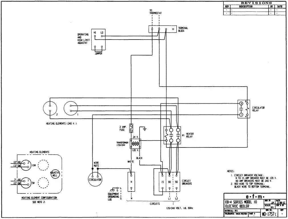
- Required electrical power input is three wire, 120/240 volt, single phase, 60 hz. (The EB4-15 and EB4-30 units may be wired using three phase power, two or three branch circuits. See wiring diagram.)
- Circuit breaker size is 60 amps per heater circuit and 15 amps for the circulator pump and control circuit. The 24 volt control circuit is protected with a 2 amp. ferrule fuse.
- An opening is provided in the cabinet lower right hand corner of the boiler for input wiring. All wiring must be in accordance with local electric code, or the National Electric Code in the absence of a local code.
Warning: DIS-CONNECT ALL WIRING AT THE MAIN SWITCH BEFORE WIRING UNIT - Connect power to terminals marked L 1 and L2 and the neutral leg of the three wire service to the terminal marked N (neutral).
- Connect a ground wire to the case ground connection and connect the ground wire to a ground that meets local electrical codes. Improper grounds may result in unsafe conditions and interfere with other electronic devices.
- Replace boiler jacket and re-install assembly screws. Remove the door holding screw to allow the door to be opened.
Re-install the door holding screw when the system is operating to avoid accidental or unintentional opening of the door. - Locate the thermostat mounting plate on a solid wall. Make sure that the backing plate for the thermostat is level by placing a level across the leveling points on the top edge of the plate. Run the two wire thermostat lead from the thermostat through the hole in the right side of the cabinet and attach to the terminals of the thermostat terminal block. If the EB4 is being installed without multiple zones controlled by valves or circulators, set the thermostat heat anticipator according to the manufacturer’s directions and the following settings:
EB4-10 = .3
EB4-15 and EB4-20 = . 5
EB4-25 and EB4-30 = . 7
The heat anticipator setting helps to anticipate a call for heat and also to anticipate reaching the thermostat set point to prevent frequent cycling. See Heat Anticipator section in this manual for zoned installations.
Caution: The Thermostat, ground wire and power wires are the only connections that should be made to the EB4. Do not supply power to any other system components from the EB4.
OPERATION
Caution: Follow the start-up procedure carefully and completely. Failure to follow the start-up procedure may cause damage to components including the heater elements.
START-UP
- Verify that the supply breaker at the main circuit breaker panel to the EB4 and all of the EB4 electrical breakers are in the off position.
NEVER PUT ELECTRICAL POWER TO BOILER UNLESS BOILER AND HYDRONIC SYSTEM ARE FULL OF WATER. - Fill the hydronic system and the boiler. Purge all air from the system at the purge valve. If it is a multi-zone system, air purge each system.
- Open the junction box on the circulator. Disconnect the power leads for the circulator. Connect an electrical jumper to the circulator power leads being careful to maintain proper polarity. Connect the jumper to a 120 volt circuit. The circulator will operate. If multiple zone circulators are installed, tum the zone circulators on. Continue to vent the system until all air is purged. Disconnect the jumper used to power the circulator and reconnect the circulator wiring. Replace the circulator junction box.
- The pressure gauge should read 12 psi if an automatic feed valve is used. If equipped with manual feed, close the system water supply valve when a pressure reading of 12 psi is obtained. The purge valve may have to be bled to reduce pressure to 12 psi.
Check the system for leaks by shutting the water supply valve and observing the pressure gage. Any decrease in system pressure indicates a leak that must be repaired prior to operation. - Set the thenmostat at the lowest setting. Turn the supply breaker for the EB4 at the main circuit breaker panel to on. Turn all EB4 breakers to on.
- Raise the thenmostat to above room temperature. The unit should operate. The pump and heater element relays will cycle on and off according to demand of the thenmostat and timing sequence. See the Sequence of Operation section in this manual for time delay description.
- The pressure of the system will rise when heated. The nonmal pressure gauge reading should be between 20 and 22 psi. If pressure rises above 22 psi, additional expansion tank capacity may be necessary. See the manufacturer’s manual for information on sizing the expansion tank.
Note:
The pressure relief valve is a safety device set to open at 30 psi. - Set the heat anticipator in the thenmostat. If this is not a multi-zone system, the heat anticipator was set previously. If this is a multi-zone system set the heat anticipator now. Check the zone valve or circulator manufacturer’s instructions for settings. Set the thenmostat heat anticipator to the proper setting. If no set point is specified, disconnect the TT tenminals at the thenmostat and using a mille-amp meter, measure the current between the two thermostat leads while the system is operating. Set the thenmostat heat anticipator to the observed reading.
When installation is complete and the system is operating satisfactorily, close the cabinet door and re-install the door
holding screw to prevent accidental or unintentional opening of the door.
SEQUENCE OF OPERATION
The thenmostat closes on a call for heat and energizes the circulator relay and the first heater relay which pulls in the circulator and two heating elements. The remaining elements are energized on at one minute intervals (two elements at one time). When the thenmostat is satisfied, all the elements de-energize at once and the circulator stops.
Operating temperatures on the temperature gage of the EB4 may be as low as 120 – 140 ° F, or lower. This is normal for the EB4.
This unit is furnished with a dual hot water control aquastat with a High Limit Safety Setting (labeled “Hi”) and an Operating Control Limit Setting (labeled “Lo”). The High Limit Safety is factory set at 200″F. The Operating Control Limit is set at 170″ If the boiler water reaches 170″ the Operating Control Limit will open the heater relay circuit causing heater elements to de-energize, even though the thermostat may be calling for heat. The circulator will continue to run, as long as
the thermostat is calling for heat. When boiler water temperature drops to 160″ the Operating Control Limit will close and bring the heating elements back on, provided that the thermostat is calling for heat.
If the water temperature reached 200″, due to a failure of the Operating Control Limit, for example, the High Limit safety will shut off all elements at once.
The High Limit Safety is set at 200° Do not attempt to change the High Limit setting.
Do not set the Operating Control Limit above 180°. Remember, this is not a low temperature set point like on an oil or gas fired boiler. There is no low set point and the circulator will run and the elements will be energized as long as the thermostat calls for heat and the Operating Control Limit and High Safety limit are not reached.
Refer to the instruction sheet for the control when making adjustments.
MAINTENANCE
A trained and experienced service person should check the system prior to each heating season. The supply breaker to the electric boiler should be off prior to performing any service.
If a component is changed in the system, follow the start-up procedure in this manual prior to operating the unit.
Check for leaks after every maintenance, once per year and if there is any visual evidence of a leak. To check for leaks, shut the water supply valve and observe the pressure gage. Any loss of pressure indicates a leak in the system that must be repaired.
Frequent heater element failures or short heater element life is an indication that there is air in the system. Follow the startup procedure to make sure that all air is eliminated from the system and verify that the system is leak-free to prevent introduction of air during operation.
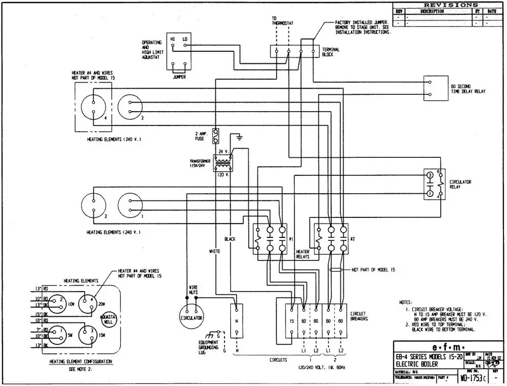
Staging
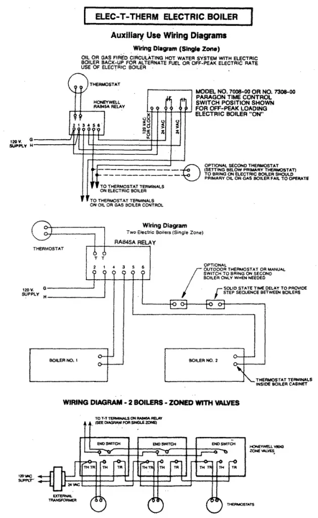
The EB4-15, 20, 25 and 30 can be “staged” using a second thermostat or a dual thermostat. Staging may be a valuable feature if the user’s electric bill is based on peak demand. Staging prevents the timed elements from energizing unless the temperature set point of a second or third thermostat is reached. A careful heat balance is required to set the EB4 for effective staged operation.
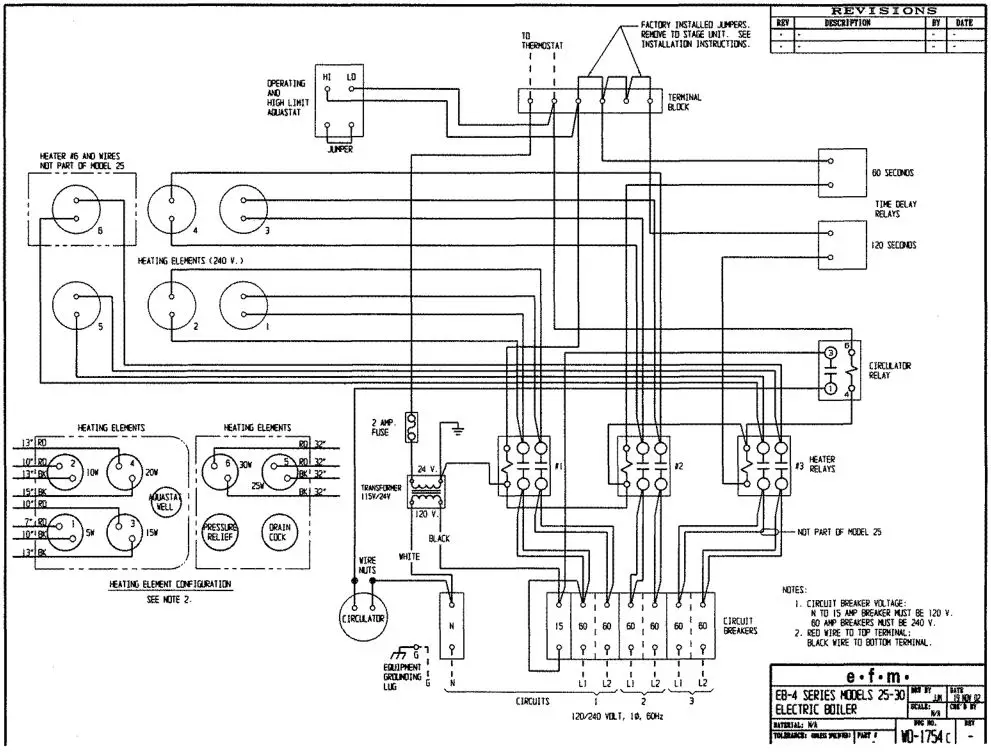
The staging terminals shown in the wiring diagrams have a factory installed jumper when delivered. When the thermostat closes on a call for heat, the first two heater elements are energized immediately. The remaining elements are energized, two at a time at one minute intervals. To stage the EB4, remove the factory installed jumper and install a thermostat or outdoor stat (Not provided) wired to the same terminals where the jumper was removed. The thermostat may be located outdoors, or in a zoned space and set or selected so that if the temperature is above the thermostat set point, heater elements that are time delayed will not turn on. If the outside temperature or a separate zone temperature is below the second thermostat set point, the time delayed heater elements will be energized after the appropriate time delay. The EB4-25 and 30 have two staging terminal sets. The second factory installed jumper can be used so that the first two heaters are energized by a call for heat from the interior thermostat and the remaining heater elements are energized only if the second thermostat set points are reached. Both sets of staging terminals can be connected to thermostats to allow two of the heater elements to come on after time delay if one set point is reached and the remaining heaters will be energized if the other set point is reached.
When using outside temperature to stage, start by setting the first staged thermostat at 40° F. Set a second thermostat at 20°F if a second stage is used. If required, adjust the thermostats to maintain desired level of comfort.


LIMITED 10 YEAR WARRANTY, Elec-T-Therm ELECTRIC BOILER
A. Full Three Year Warranty. e•f•m warrants the Elect-T~Therm boiler units are free from defects in material and workmanship for 3 years from date of installation. If any parts are found to be defective in manufacture, e•f•m wil1 repair or replace them at e•f•m’s option.
B. IO Year Warranty. e•f•m warrants that the steel boiler heat exchanger of the Elect-T-Therm is free from defects in material and workmanship through the I 0th year following the date of installation. Any boiler found defective will be repaired or replaced at e•f•m’s option.
This warranty does not cover:
- Boilers located out of doors.
- Components of the heating system not supplied by efrn.
- Workmanship of the installer. This warranty does not assume any liability of any nature for unsatisfactory performance caused by improper installation.
- Failures due to shipping damage. Any evidence of shipping damage must be reported to the shipping company immediately and a claim filed. Do not install the boiler.
- Improper adjustments, control settings, care, maintenance or failure to fo1low installation instructions provided with the boiler.
- Defects resulting from freezing, excessive pressure, temperature or leaks at water connections or any simi1ar cause.
- Any installation that has been modified, neglected, altered, tampered with, vandalized, misused, or otherwise subjected to accident, fire, flood or other casualty.
- Installations for which a heat balance provided by an experienced heating professional indicates that the boiler is inadequate for the application.
This warranty does not extend to anyone except for the first purchaser at retail. and only when the boiler is in the original installation site, which must be within the continental limits of the United States.
Implied warranties of fitness for a particular purpose and merchantability shall be limited to the duration of the express warranty. e•f•m expressly disclaims and excludes any liability for consequential or incidental damages for breach of any express or implied warranty, except as otherwise provided by state law.
For prompt service, notify the installer, who in turn will notify the distributor who supplied the boiler. If this does not result in prompt service, contact e•f•m Sales Company, 4th and Furnace Streets, Emmaus, PA 18049. Alleged defective parts must be returned in accordance with the e•f•m procedure currently in force. e•f•m will provide the new parts to the installing dealer or distributor.
This warranty gives you specific legal rights. You may have other rights that vary from state to state.
Power Supply Wire Sizes
Split Power Supply

Single Power Supply
