![]()
EZ8WSLSMC_1G EZ8WSSSMC_1G LZ8WSLSMC_1G LZ8WSSSMC_1G
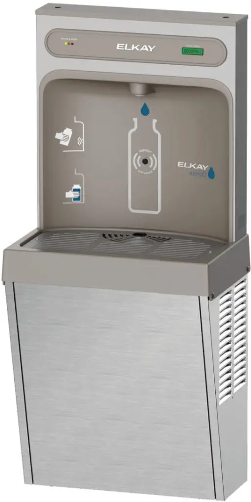
Elkay EZH2O Refrigerated Surface
Mount Bottle Filling Station(s)
series EZ8WS & LZ8WS
USE AND CARE GUIDE
General Information
Use and Care Guide
Read all instructions carefully and familiarize yourself with the various parts of this product. This manual contains step-by-step adjustment, and maintenance instructions for the EZ8WS and LZ8WS series bottle filling stations and cooler. Following carefully, these instructions will result in trouble-free use of this Elkay Manufacturing Company (Elkay) product. Any deviations, additions, and/or deletions from the described methods, without the prior written approval of Elkay, will void the warranty covering this product. Save these instructions for future reference
![]() WARNING
WARNING
![]() To avoid product or property damage, personal injury, or even possible death, carefully read, understand, and follow all the instructions in this Use and Care guide before installing his product. Improper installation of this product could cause a dangerous situation that results in injury or death. Do not operate power tools unless you read and understand the instructions and warnings in this and all other applicable labels or manuals. Proper use of tools and the products described in this guide is your responsibility. Failure to follow these instructions could result in personal injuries, water damage, and other damage to floors, pipes, walls, and other portions of your building or home.
To avoid product or property damage, personal injury, or even possible death, carefully read, understand, and follow all the instructions in this Use and Care guide before installing his product. Improper installation of this product could cause a dangerous situation that results in injury or death. Do not operate power tools unless you read and understand the instructions and warnings in this and all other applicable labels or manuals. Proper use of tools and the products described in this guide is your responsibility. Failure to follow these instructions could result in personal injuries, water damage, and other damage to floors, pipes, walls, and other portions of your building or home.
Disclaimer
The information contained in this Use and Care guide is given free of charge. It is based upon technical data which we believe to be reliable and is intended for use by persons having knowledge of this technical area at their own discretion and risk. Elkay assumes no responsibility for results obtained or damage incurred from the use of this material either in whole or in part by the buyer.
Serial Number Location
Please use the serial number located on the underside of the water cooler shroud when contacting us with questions concerning the installation of this product.

Contact Information
General Information
Elkay Manufacturing Company 1333 Butterfield Road Suite 200 Downers Grove, IL 60515
Phone: 630.574.8484
Email: [email protected]
Website: http://www.elkay.com
USA/Canada Customer Care
Phone: 800.476.4106
Email: [email protected]
International Customer Care
Phone: 630.575.4755
Email: [email protected]
Installation Services
Phone: 800.952.8064
Email: [email protected]
Website: http://www.elkay.com/contact-us/install
Notice of Changes
The information, specifications, and illustrations in this manual are based on the information that was available at the time this material was written and can change at any time. In keeping with our policy of continuous product improvement, Elkay reserves the right to change specifications without notice.
Warranty
This product is covered by a Limited Warranty and Elkay will not be held responsible for damage of any kind in connection with the installation of the product. Refer to the Elkay website http://www.elkay.com/warranty and click on Warranty for Drinking Water Products under the Info and Maintenance section (form 96993C).
Safety
![]() Think Safety
Think Safety
Before performing any work, read and understand the safety instructions in this manual.
General
The Elkay Manufacturing Company (Elkay) cannot anticipate every possible circumstance that might involve a potential hazard during the installation or maintenance of this product. The warnings and instructions in this Use and Care guide, therefore, are not all-inclusive. If a tool, installation procedure, or work method that is not specifically recommended by Elkay is used, you must be satisfied that it is safe for yourself and others. You should also make sure that the product will not be damaged by the methods you choose. Most work-related accidents are caused by failure to observe basic safety rules or precautions. An accident can often be avoided by recognizing potentially hazardous situations before an accident occurs. As you install and maintain this product, you must be alert to potential hazards. You should also have the necessary training, skills, and tools to perform any installation or maintenance procedure.
Safety Alert Symbol
 This is the safety alert symbol. It is used to alert you to potential personal injury hazards. Obey all safety messages that follow this symbol to avoid possible injury or death. This manual contains WARNINGS, CAUTIONS, NOTICES, SAFETY INSTRUCTIONS, and NOTES which must be followed to prevent the possibility of improper service, damage to the equipment, personal injury, or death. The following keywords call the reader’s attention to potential hazards. Hazards are identified by the “Safety Alert Symbol” and followed by a signal word such as “WARNING” or “CAUTION”.
 WARNING
These warnings indicate a potentially hazardous situation that, if not avoided, could result in serious injury or death. Follow all instructions related to the installation and/or maintenance of this product (unit).
 Personal Protection
Be sure to use all personal protective equipment, such as sturdy safety glasses, work shoes, hearing protection, and gloves, whenever necessary, to ensure your own safety.
![]() To avoid eye injury, always wear protective glasses with side shields when using power tools. Also, make sure no one else can be injured by flying particles when using power tools.
To avoid eye injury, always wear protective glasses with side shields when using power tools. Also, make sure no one else can be injured by flying particles when using power tools.
![]() To prevent possible damage to your hearing, always wear ear protection, such as earmuffs or earplugs, when using power tools.
To prevent possible damage to your hearing, always wear ear protection, such as earmuffs or earplugs, when using power tools.
![]() This product is heavy and can cause bodily injury, due to its weight or if the unit is dropped. Use two people to lift the product when unpacking the unit or installing it onto the hanger brackets.
This product is heavy and can cause bodily injury, due to its weight or if the unit is dropped. Use two people to lift the product when unpacking the unit or installing it onto the hanger brackets.
![]() Wear protective gloves during installation to protect against sharp edges from sheet metal components.
Wear protective gloves during installation to protect against sharp edges from sheet metal components.
![]() Lifting Hazard
Lifting Hazard
- To avoid personal injury, always use these proper lifting techniques and use two
- Use appropriate lifting devices to move the load.
- Always use two people when lifting heavy or bulky cartons. DO NOT attempt to lift objects that are too heavy.
![]() Power Tool Hazard
Power Tool Hazard
To prevent personal injury or possible death, always follow the electrical safety recommendations of the power tool’s manufacturer.
- Do not use power tools in an unsafe manner.
- Power tools should only be connected to a circuit protected by a ground-fault circuit interrupter (GFCI).
- If an extension cord is required, always use an OSHA-approved extension cord.
![]() Shock and Electrocution Hazards
Shock and Electrocution Hazards
Failure to follow these instructions could result in severe burns, significant injuries, and even death.
![]() Water will conduct electric current to create a short circuit, resulting in injury or death.
Water will conduct electric current to create a short circuit, resulting in injury or death.
- Never use electric power tools around water or wet floors/surfaces.
- Keep all liquids away from electrical cords and power tools.
- If an extension cord is required, always use an OSHA-approved cord.
- DO NOT create a short circuit between a source of electricity and a liquid by being in contact with both simultaneously
![]() Contacting live electrical wiring with power tools or hand tools can cause serious injury or death.
Contacting live electrical wiring with power tools or hand tools can cause serious injury or death.
- Make sure all related circuit breakers are turned OFF.
- Test for live circuits or wiring inside any wall where installation of the product requires cutting into a wall.
 Prior to any maintenance, make sure the unit is unplugged and circuit breakers are turned OFF.
 Prior to installation, test for live circuits or wiring inside the wall before cutting or drilling into the wall.
 WARNING
These cautions indicate a potentially hazardous situation that, if not avoided, may result in minor or moderate injury. Follow all instructions related to the installation and/or maintenance of this product.
![]() Tripping Hazard
Tripping Hazard
Personal injury can result from tripping over
power cords, tools, or other installation items.
DO NOT leave items laying around the work area.
![]() Cutting Hazard
Cutting Hazard
The installation of this product may require using power tools. Keep hands away from the cutting edge of any tool used in the installation of our product. Placing fingers in or around the cutting blades could result in serious personal injury.
Changing the Factory Default Settings (Not Required for Installation)
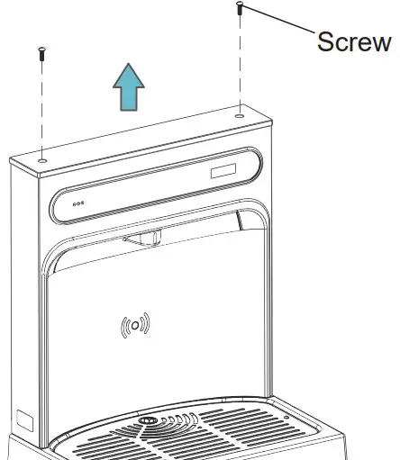
Accessing the Programming Button
- Remove the bottle filler top cover by removing the two screws using a 5/32” Allen wrench. Do not discard the screws, they are required for re-assembly.
- Locate the programming button at the top right side of the unit on the control board.
Access the Programming Menu
- Depress the program button for approximately two seconds until the display changes, then release.
- The display will scroll through two messages.
a. RST FLTR – Reset Filter Monitor (filtered units only).
b. SETTINGS – System Setting Sub Menu. Depress the program button when the display reads
SETTINGS. The display will scroll through four messages:
• RNG SET – Range set for IR sensor. Default is 3.
• UNIT TYP – Type of unit. Default is refrigerated.
• FLT SIZE – Select filter capacity. Default is 3000 GAL.
• RST BCNT – Reset bottle count (filtered units only). - Push the button while the desired message is displayed. If the program button is not pushed, the messages will cycle three times before resetting back to run mode.
Reset the Filter Monitor (Filtered Unit Only)
- Depress the program button when the display reads RST FLTR.
- Depress the program button when the display reads FLTR = and the display will change to FLTR = 0.
- The green LED on the bottle filler panel should now be illuminated indicating that the filter monitor has been reset.
Change the Range Of The IR Sensor
- Depress the program button when the display reads RNG SET.
- The display will show the default RNG = 3. 1-10 is the range, 1 is closest to the sensor, 10 is farthest away.
- Depress the button again to change the value. When the desired range is selected, wait four seconds for the unit to default back to run mode.
- Test the bottle filler by placing a hand or a bottle in front of the sensor.
Change the Unit Type
- Depress the program button when the display reads UNIT TYP.
- The display will show the default REFRIG.
- Depress button to change to refrigerated if NONREFRIG is displayed.
- When the desired range is selected, wait four seconds for the unit to default back to run mode.
- Test the bottle filler by placing a hand or a bottle in front of the sensor.
Change the Filter Capacity (Filtered Unit Only)
- Depress the program button when the display reads FLT SIZE.
- The display will show the default 3000GAL.
- Depress the button again to change the value to 6000GAL.
- When the desired range is selected, wait four seconds for the unit to default back to run mode.
Resetting the Bottle Count
- Depress the program button when the display reads RST BCNT.
- The display will show the current value, e.g. 0033183.
- Depress the button again to change the value to 0. The display will show BTLCT = 0 for approximately 2 seconds and return to run mode showing 0000000 on the display board.
Resetting the Bottle Count
1. Depress the program button when the display reads RST BCNT.
2. The display will show the current value, e.g. 0033183.
3. Depress the button again to change the value to 0. The display will show BTLCT = 0 for approximately 2 seconds and return to run mode showing 0000000 on the display board.
Note: Once the bottle count is reset to 0, there is no way to return to the previous count.
- Test the bottle filler by placing a hand or a bottle in front of the sensor and dispensing product until the bottle count changes to 1.
Cleaning Instruction
Stainless Steel
- General Cleaning: Use an ordinary mild detergent and soft cloth, rinse and towel dry.
- Steel soap pads should never be used; particles can adhere to a stainless steel basin surface and will eventually rust.
- Light scratches are normal for stainless steel basins; Over over time, they will blend into the uniform finish pattern.
Plastic Components
- General cleaning: Use an ordinary mild detergent and soft cloth, rinse and towel dry.
- Wiping the surface clean to remove debris or build-up will not hurt the antimicrobial properties.
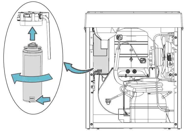
Filter Cartridge Replacement for Filtered Units Only
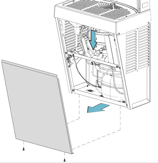
- Remove the front cover of the cooler by removing two 5/16″ screws located on the bottom of the cooler.

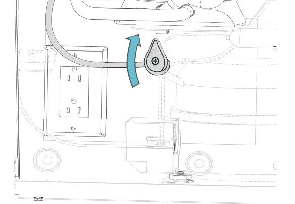
- Shut the off water supply using the shut off valve. Turn the water shut off valve handle to the OFF position (clockwise).
Note: This view may be different depending on the model and configuration.
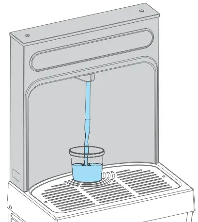
- Activate the water dispenser with a water bottle to relieve pressure and access water in the waterline.
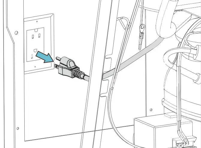
- Shut OFF power to the unit by unplugging.
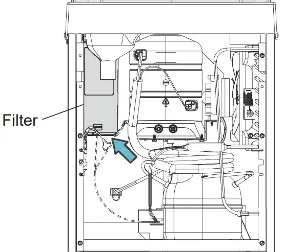
- Locate the current filter on the left side of the cooler.
- Place a towel under the filter to absorb any water that leaks out of the filter when it is removed.
- Twist the filter counterclockwise until it is disengaged. Remove the filter and keep it upright; remove the towel.
- Drain the filter before disposing of it in a trash can.
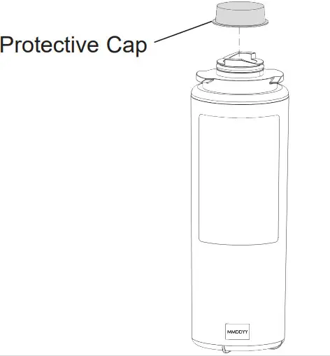
- Remove the protective cap from the new filter.

- Mark the current date on the filter label.
- Attach the filter to the filter head with the label facing outward by fi rmly inserting it into the head and by rotating the fi lter head clockwise, if required.
Note: The filter label should be readable from the front of the filter during installation.
- Restore power back to the unit.
- Turn on the water supply.
- Verify proper dispensing by placing a cup or any object in front of sensor area and verifying water dispenses. Dispense at least two gallons of water to bleed off any trapped air from supply lines and fi ne carbon particles from the fi lter.
- Check all the lines and connections for water leaks. Repair connections if necessary. If there are no leaks and the unit is functioning correctly.
- Reinstall front panel with 5/16” screws.
 Note: Once power is applied to the bottle filler, the GREEN LED light should illuminate showing good filter status (if equipped with filter) along with the LCD Bottle Counter.
GREEN: 0 – 80% of Filter Life or 0 – 11 Months (Whichever Comes First).
YELLOW: 80 – 100% of Filter Life or 11 – 12 Months (Whichever Comes First).
RED: 100% Plus of Filter Life or 12 Months (Whichever Comes First). - Reset the filter status indicator:
The programming button is located at the top right side of the unit on the control board.
- To access the program button, take off the top cover of the bottle filler by removing the two screws holding it in place.
- Remove the screws using a 5-32 inch Allen wrench (Do not discard the mounting screws; they will be needed to reinstall the top cover once programming is complete).

- Remove the top cover.
- To remove the cover, depress the program button when the display reads RST FLTR.
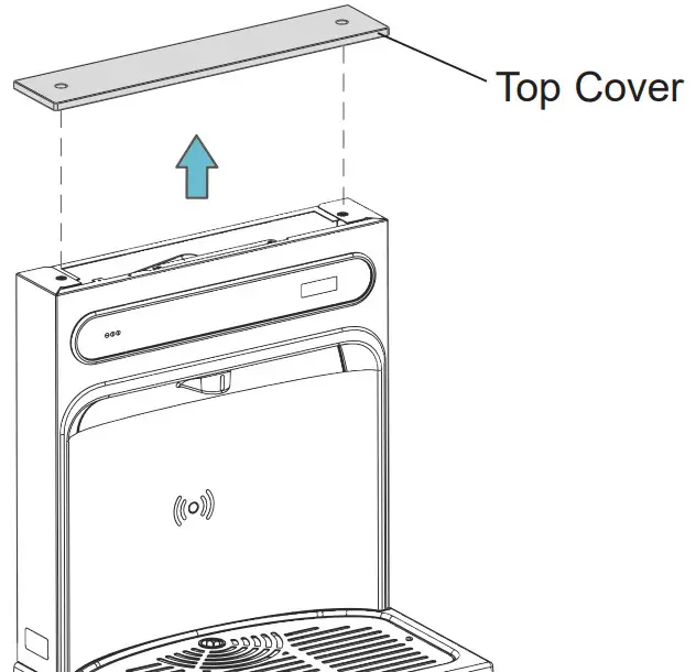
- Depress the program button when the display reads FLTR = and the display will change to FLTR = 0.
- The green LED on the bottle filler panel should now be illuminated indicating that the filter monitor has been reset.
- Filter Reset is complete.
Picture is Cooler Only Without Bottle Filler
Note: Danger! Electric shock hazard. Disconnect power before serving unit.
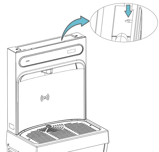 Fig 1: Cooler Top View (EZ8WS Shown)
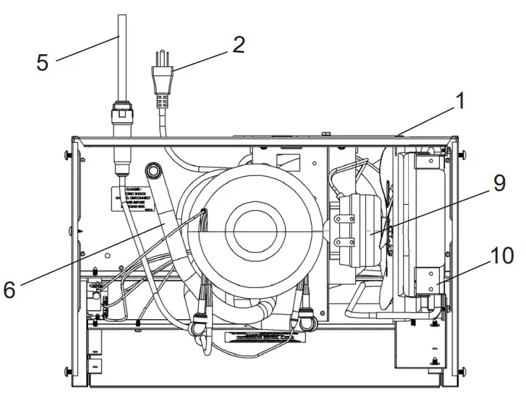 Fig 2: Cooler Front View
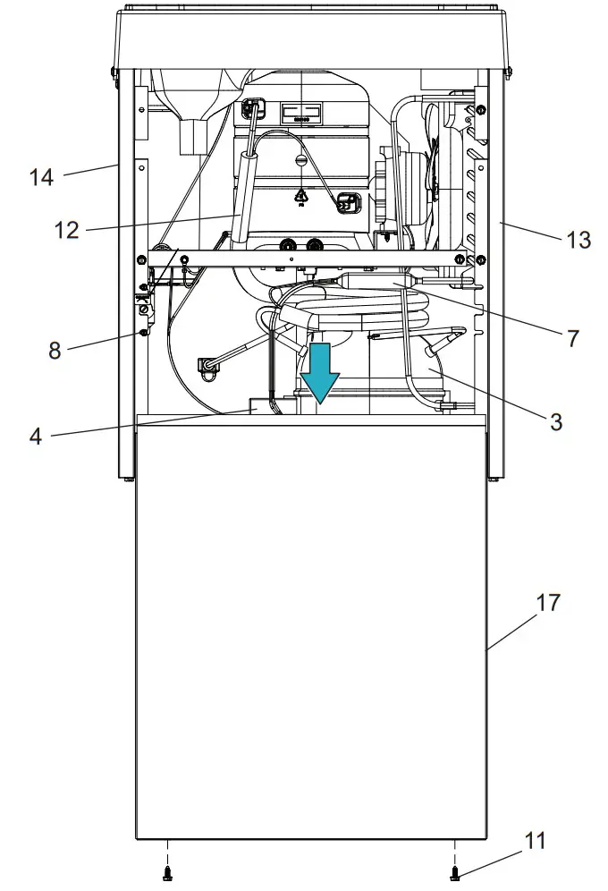 Fig 3: Basin Cover
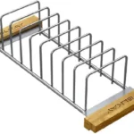
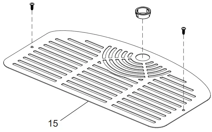 Fig 4: Basin Assembly Kit
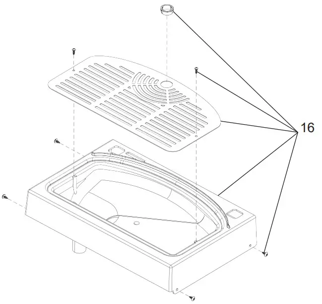
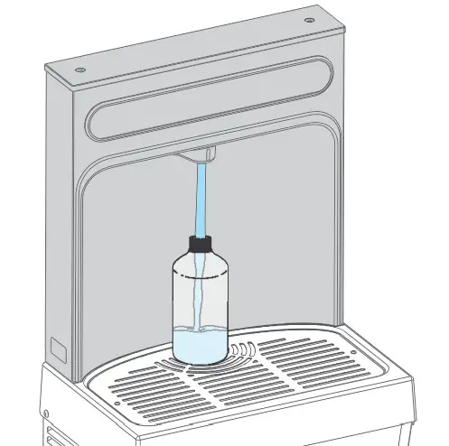
Fig 5: Front View with Aerator
Operation of Quick Connection Fitting
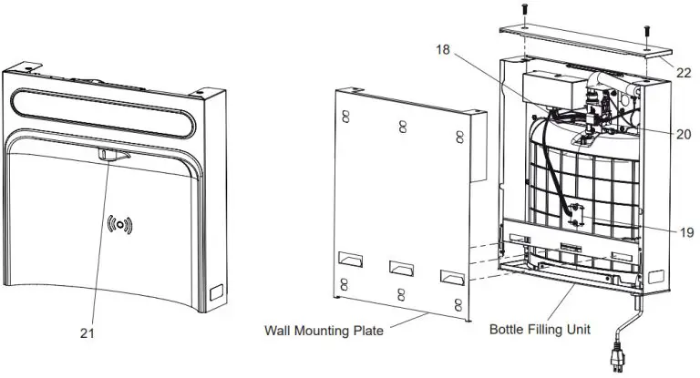 Fig 6: Poly Tube Quick Connect Fitting
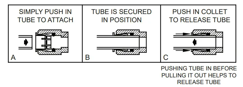 Fig 7: Filter and Filter Head
| FILTER PARTS LIST
(See Fig 7: Filter and Filter Head) |
||
| ITEM NO. | PART NO. | DESCRIPTION |
| 1 2 |
51300C 0000000746 |
Filter Assy-3000 Gal Assy-Filter & Bracket includes Fltr Head/Mtg Bkt/John Guest Ftgs/Screws |
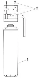 Fig 8: 115V Wiring Diagram
Cooler Parts List
| ITEM NO. | PART NO. | DESCRIPTION |
| 1 2 3 4 5 6 7 8 9 10 11 12 13 14 15 16 17 – |
28551C 36208C *36322C 0000000238 55996C 56092C 66703C 98773C 98775C 98776C 98777C 98778C 28525C 28528C 2000000075 2000000076 1000006133 See Filter Table |
Hanger Bracket Power Cord Compressor Serv. Pak EMIS70HHR Kit – Electricals /OL/Relay/Cvr Strainer (See “General Instructions”) Tubing – Poly (Cut To Length) Drier Kit – Cold Control/Screws Kit – Fan Motor Assy/Blade/Motor/Shroud/Nut Kit – Condenser/Drier Kit – Compr Mtg Hdwe/Grommets/Clips Studs Kit – Heat Exchanger/Drier Panel – Right Rear Panel – Left Rear Kit – Basin Cover Kit – Basin Assembly Panel – Front Cover Water Filter Kit (When Provided) |
Bottle Filler Parts List
| ITEM NO. | PART NO. | DESCRIPTION |
| 18 19 20 21 22 |
98543C 98544C 1000004573 98546C 98547C |
Kit – Electrical Package Kit – IR Sensor Kit – Solenoid Valve Replacement Kit – Aerator ReplacementKit – Top Cover Replacement |
![]() *Replace With Same Compressor Used in Original Assembly.
*Replace With Same Compressor Used in Original Assembly.
Note: All correspondence pertaining to any of the above
components for repair parts MUST include Model
No. and Serial No., name and part number of
replacement part.