EMERSON Single Stage Thermostat Installation Guide
INDEX
| Thermostat Installation | 2-4 |
| Wiring | 2 |
| Installer Menu | 3-4 |
| Using the Thermostat | 5-7 |
| Thermostat Overview | 5 |
| User Menu | 6 |
| Thermostat Operation | 6 |
| Troubleshooting | 7-8 |
| Homeowner Help Line | 8 |
| Thermostat Applications | Maximum Stages Heat/Cool |
| Conventional Gas, Oil, Electric (mV and 24V), Heat Only, Cool Only or Heat/ Cool Systems | 1/1 |
| Heat Pump (air source or geothermal) with no Aux. Heat | 1/1 |
MERCURY NOTICE: This product does not contain mercury. However, this product may replace a product that contains mercury. Mercury and products containing mercury must not be discarded in household trash. Refer to www.thermostat-recycle.org for information on disposing of products containing mercury.
SPECIFICATIONS
Electrical Rating:
Battery Power……………………………….. mV to 30 VAC, NEC Class II, 50/60 Hz
Input-Hardwire………………………………. 20 to 30 VAC, NEC Class II, 50/60 Hz
Terminal Load………………………………….. 1.0 A per terminal, 1.5A maximum all terminals combined
Setpoint Range…………………………………. 45° to 99° F (7° to 37° C)
Rated Differentials: Fast Med Slow
Heat (@ 6°F/ Hr)…………………………….. 0.5°F 0.75°F 1.9°F
Cool (@ 6°F/ Hr)…………………………….. 0.9°F 1.2°F 1.7°F
Operating Ambient…………………………….32°F to +105°F (0° to +41°C)
Display Temperature Range……………… 32°F to +99°F (0 to 37°C)
Operating Humidity……………………………90% non-condensing max
Shipping Temperature Range……………..20°F to + 150°F (-29° to +65°C)
Thermostat Dimensions…………………… 3-3/4” H x 6” W x 1-1/8” D
THERMOSTAT INSTALLATION
WIRING
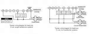
Refer to equipment manufacturer’s instructions for specific system wiring information. After wiring, see INSTALLER MENU for proper thermostat configuration. Wiring table shown are for typical systems and describe the thermostat terminal functions.
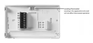
| Terminal Designations | Terminal Function |
| RC* | Power for Cooling |
| RH* | Power for Heating |
| O/B | Changeover Terminal-Energized in Heat (B) or Cool (O) for Heat Pump or Damper Systems |
| Y** | Cooling Relay |
| G | Fan Relay |
| W** | Heating Relay |
| C | Common wire for 24V (optional with batteries) |
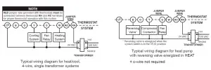
*When both RC and RH wires are present, cut RC/RH jumper (see next page).
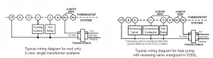
**For heat pump systems, add a jumper wire to connect terminals Y and W
Precautions
- Do not exceed the specification ratings.
- All wiring must conform to local and national electrical codes and ordinances.
- This control is a precision instrument, and should be handled carefully. Rough handing or distorting components could cause the control to malfunction.
WARINING
Do not use on circuits exceeding specified voltage. Higher voltage will damage control and could cause shock or fire hazard.
Do not short out terminals on gas valve or primary control to test. Short or incorrect wiring will burn out thermostat and could cause personal injury and/or property damage
CAUTION
To prevent electrical shock and/or equipment damage, disconnect electrical power to system, at main fuse or circuit breaker box,until
installation is complete.
1.) Gas/Elec Switch
If the system is a heat pump or electric furnace, the GAS/ELEC Switch must be set to Elec. If your system is a gas or oil furnace, the switch must be set to Gas.
2.) O/B Terminal Switch
The O/B switch on this thermostat is factory set to the O position. This will accommodate the majority of heat pump applications, which require the changeover relay to be energized in Cool. If the heat pump being installed requires a B terminal, to energize the changeover relay in Heat, the O/B switch must be moved to the B position.
3.) RC/RH Jumper Wire
This thermostat electrically connects the RC and RH terminals so a jumper wire is not required. If the application provides a separate wire for RC and RH, clip the RC/RH jumper. This will isolate both terminals so they can be independently used.
INSTALLER MENU
To prevent changes that may affect system performance, this thermostat has an INSTALLER’S MENU and an USER MENU. The INSTALLER’S MENU provides access to every option, while the USER MENU provides access to items that will not affect system performance. To access the INSTALLER’S MENU press the Menu button for 8 seconds. The display will show item 30 in the table below. Use Next and Back to navigate through menu items. Press or to change a menu setting.
| Installer’s Menu #
(Hold Menu 8 Seconds) |
Description | Default Setting
(flashing icons) |
Settings
(Press or) |
 |
Heat Cycle Rate (how often the heat will turn on) | MEd | SLO – slow MEd – medium FAS – fast |
 |
Cool Cycle Rate (how often the cooling will turn on) | MEd | SLO – slow MEd – medium FAS – fast |
 |
Compressor Lockout (protects the compressor from short cycling) | OFF | On – 5 minute display
OFF – no delay |
| 65 | Maximum Heat Limit
(maximum set point for heat mode) |
99 | 47 to 99 |
| 66 | Minimum Cool Limit (minimum set point for cool mode) | 45 | 45 to 97 |
INSTALLER MENU (C0ntinued)
| Installer’s Menu #
(Hold Menu 8 Seconds) |
Description | Default Setting
(flashing icons) |
Settings |
| 79 | Fahrenheit or Celsius | °F | °F – Fahrenheit
°C – Celsius |
| 81 | Temperature Display Adjustment (adjust the displayed “Room Temperature”) |
0 |
-5 to +5 |
 |
Continuous Display Light (keep the backlight always on – “C” wire required) |
OFF |
On – always on
OFF – momentarily |
 |
Keypad Lock (prevent unwanted changes to the thermostat) |
OFF |
On – disable buttons
OFF – all buttons are active |
TEST EQUIPMENT
Turn on power to the system. Fan Operation
If your system does not have a G terminal connection, skip to Heating System.
- Move fan switch to On position. The blower should begin to operate.
- Move fan switch to Auto position. The blower should stop immediately.
Heating System
- Move System Switch to Heat position.
- Press to adjust thermostat setting to 1° above room temperature. The system should begin to operate and the thermostat will indicate Heat On.
- Press to adjust thermostat setting 1° below room temperature. The heating system should stop operating and the thermostat should indicate Heat.
Cooling System
- Move System Switch to Cool position.
- Press to adjust thermostat setting 1° below room temperature. The blower should come on immediately on high speed, followed by cold air circulation. The thermostat will indicate Cool On. There can be up to a 5 minute delay. (see INSTALLER MENU, item 50)
- Press to adjust thermostat setting to 1° above room temperature. The cooling system should stop operating and the thermostat will indicate Cool.
Note: If Starting Soon is shown on the display, the compressor lockout feature is operating. There will be up to a 5 minute delay before the compressor turns on.(see INSTALLER MENU, item 50)
CAUTION
To prevent compressor and/or property damage, if the outdoor temperature is below 50°F,
DO NOT operate the cooling system.
Do not allow the compressor to run unless the compressor oil heaters have been operational for 6 hours and the system has not been operational for at least 5 minutes.
USING THE THERMOSTAT
THERMOSTAT OVERVIEW
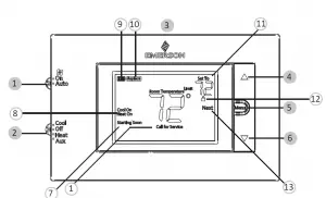
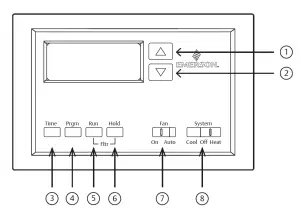
Before you begin using your thermostat, you should be familiar with its features, display and the location/operation of the thermostat buttons and switches.
| THERMOSTAT BUTTONS AND SWITCHES | THE DISPLAY |
| 1.) Fan Switch | 7.) Thermostat is protecting the equipment from short cycling (5-minute delay) |
| 2.) System Switch | 8.) Indicates that the system is running in cool or heat |
| 3.) Backlight Button (located on the top of the thermostat | 9.) Battery status indicator |
| 4.) Raises Temperature Setting | 10.) Low battery indicator * |
| 5.) Access Menu Options | 11.) Temperature setpoint |
| 6.) Lowers Temperature Setting | 12.) Appears when the keypad is locked (to prevent unwanted changes) |
| 13.) Next (Menu button) is used to navigate within a menu | |
| 14.) SEE TROUBLESHOOTING |
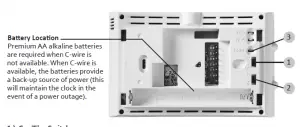
* Whenever “ Replace  ” appears in the display, new premium brand AA alkaline batteries should be installed. If the house will be unoccupied for an extended period and either “
 ” or “
Replace ” is displayed, install new batteries before leaving.
USER MENU
To customize thermostat settings, press and hold the Menu button for ½ second from the home screen. Use the Next button to advance through menu items. Press or to change the setting.
| User’s Menu # (Press Menu button and release) | Description | Default Setting
(flashing icons) |
Settings
(Press or ) |
 |
Continuous Display Light (keep the backlight always on – “C” wire required) | OFF | On – always on
OFF – momentarily |
• Keypad Lockout – To prevent unwanted changes, the buttons can be disabled. To turn this feature On, press and hold and the Menu button until the icon appears (this can also be turned on in the menu). To turn Off, press and hold and the Menu button for 3 seconds.
TROUBLESHOOTING
| Symptom | Possible Cause | Corrective Action |
| No Heat/ No Cool/ No Fan
(common problem) |
1.) Blown fuse or tripped circuit breaker
2.) Furnace power switch to OFF 3.) Furnace blower compartment door panel loose or not properly installed 4.) Loose connection to thermostat or system |
1.) Replace fuse or reset breaker
2.) Turn switch to ON 3.) Replace door panel in proper position to engage safety interlock or door switch 4.) Tighten Connections |
| No Heat | 1.) System Switch not set to Heat
2.) Loose connection to thermostat or system 3.) Heating System requires service or thermostat requires replacement |
Verify thermostat and system wires are securely attached.
Diagnostic: Set System Switch to Heat and raise the setpoint above room temperature. Within five minutes the thermostat should make a soft click sound and “Heat On” should appear on display. This sound indicates the thermostat is operating properly. If the thermostat does not click, try the reset operation listed below. If the thermostat does not click after being reset, contact your heating and cooling service person or place of purchase for a replacement. If the thermostat clicks, contact the furnace manufacturer or a service person to verify the heating system is operating correctly. |
| No Cool | 1.) System Switch not set to Cool
2.) Loose connection to thermostat or system 3.) Cooling System requires service or thermostat requires replacement |
Verify thermostat and system wires are securely attached.
Diagnostic: Set System Switch to Cool and lower setpoint below room temperature. Same procedures as diagnostic for “No Heat” condition except set the thermostat to Cool and lower the setpoint below the room temperature. There may be up to a five minute delay before the thermostat clicks in Cooling if the compressor lock-out option is selected in the installer menu. (see INSTALLER MENU, item 50) |
| Heat, Cool or Fan Runs Constantly | Possible short in wiring, thermostat, heat, cool or fan system | Check each wire connection to verify they are not shorted or touching other wires. Try resetting the thermostat. If the condition persists contact your HVAC service person. |
| Thermostat Display & Thermometer Disagree | Thermostat display requires adjustment | Display can be adjusted +/-5°. See User Menu item
04 |
(Troubleshooting continued on next page)
| Symptom | Possible Cause | Corrective Action |
| Furnace (Air Conditioner) Cycles Too Fast or Slow (narrow or wide temperature swing) |
The location of the thermostat and/or the size of the Heating System may be influencing the cycle rate |
Digital thermostats provide precise control and cycle faster than older mechanical models. The system turns on and off more frequently but runs for a shorter time. If you would like to increase cycle time, choose SLO for slow cycle in the Installer menu. (Reference menu items 30 & 35) If an acceptable cycle rate is not achieved, contact your HVAC service person. |
|
“Call for Service” icon appears on displayed |
1.) Heating system is not able to heat the space to within 10 degrees of the setpoint within 2 hours
2.) Cooling system is not able to cool the space to within 10 degrees of the setpoint within 2 hours 3.) If “–” is displayed for the Room Temperature, a replacement thermostat is needed 4.) None of the buttons operate on the thermostat |
1.) See corrective action for “No Heat”
2.) See corrective action for “No Cool”
3.) Replace thermostat
4.) Make sure keypad lockout is not turned on (denoted by icon) |
Resetting the Thermostat or Thermostat Settings
If the thermostat has good batteries, but has a blank display or does not respond to key presses, the thermostat should be reset by removing the batteries for 2 minutes. This reset will not change the menu settings. If the condition persists after reinstalling the batteries, replace the thermostat.
To conveniently reset only the user settings back to factory defaults, press Menu and Backlight buttons at the same time and hold until the display goes blank and resets.
WARNING: This product contains a chemical known to the state of California to cause cancer and birth defects and other reproductive harm.
]]>
Product Overview
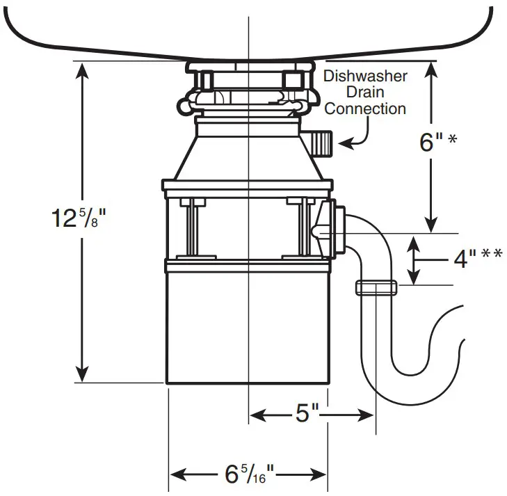
Dimensions

- Distance from bottom of sink to center line of disposer outlet.
Add 1/2″ when stainless steel sinks are used. - Length of tailpipe from center line of disposer outlet to end of tailpipe.
NOTE: Plumb waste line to prevent standing water in disposer motor housing.
Job Specifications
____________________________________________________
Submittal Sheet
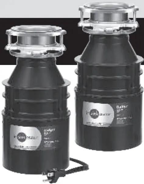
Our Badger 5XP® model provides more power and a longer warranty than the Badger® 5 or Badger® 1.
This model also offers the following features and benefits:
- 3/4 Horsepower Heavy Duty Motor (Quiet Dura-Drive® Induction Motor)
- 4-Year We Come To You® In-Home Parts And Labor Service Warranty
- Rugged Galvanized Steel Construction (For Disposer Durability)
- Space-Saving Compact Design
- Available with or without a factory installed power cord.
Sample Specification
Food Waste Disposer(s) shall be InSinkErator Badger 5XP®, continuous feed, with 3/4 H.P. motor, galvanized steel grinding elements with two stainless steel 360° swivel lugs. Self-service wrench.
Available with or without a factory installed power cord.
Warranty:
4- Year parts and in-home service.
The complete InSinkErator warranty is included in the Care & Use Booklet packed with each unit.
Specifications
| Type of Feed | Continuous |
| On/Off Control | Wall Switch |
| Motor | Single Phase |
| HP | 3/4 |
| Volts | 120 |
| HZ | 60 |
| RPM | 1725 |
| Amp. (Avg. Load) | 9.5 |
| Time Rating | Intermittent |
| Lubrication | Permanently Lubricated Upper & Lower Bearings |
| Shipping Weight (Approx.) | 15 lbs. 2 oz. |
| Unit Finish | Waterborne Grey Enamel |
| Overall Height | 12-5/8″ |
| Grind Chamber Capacity | 26 oz. |
| Motor Protection | Manual Reset Overload |
| Average Water Usage | Approx. 1 Gallon per Person Per Day |
| Average Electrical Usage | 3-4 KWh per Year |
| Drain Connection | 1-1/2″ Cushioned Slip Joint |
| Dishwasher Drain Connection | Yes |
| Factory Installed Power Cord | Available with or without |
 Food waste is roughly 80% water. By using your disposal regularly, you can help divert food waste from landfills and reduce greenhouse gas emissions. Make sustainability a family affair by using your disposal. After all, the smallest changes can make the biggest impact.
Call: 1-800-558-5700
Visit: www.insinkerator.com

The Emerson logo is a trademark and service mark of Emerson Electric Co. The mounting collar configuration is a trademark of Emerson Electric Co. Quick Lock ® is a registered trademark of Emerson Electric Co.
InSinkErator may make improvements and/or changes in the specifications at any time, in its sole discretion, without notice or obligation and further reserves the right to change or discontinue models.

A universal solution for residential air conditioning applications
Introduction
Your customers want a better performing AC system and energy efficiency savings. You need a quick and efficient way to meet your customer’s need. With Emerson TXV Connect kits, you have all you need to upgrade your customer’s AC and heat pump system while saving you time and money.
TXV Connect kits include our latest generation thermostatic expansion valves, external equalizer plus Chatleff and Aeroquip adapters that are easy to install into all residential air conditioning systems. You can be certain to have the TXV replacement you need regardless of the manufacturer.
Features
- Save Time

Everything you need in one box
ODF TXV with internal check, Chatleff and Aeroquip adapters, external equalizer connector, bulb strap
R-410A and R-22 kits in multiple capacities - Save Money

Fits all systems regardless of manufacturer
Packaged kit more economical than purchasing individual components - Install with Ease

Adapters with extended ends
R-410A valves offer stainless steel power assembly for durability
Superheat adjustment table included on box - Provide Energy Cost Savings

Provide customers increased efficiency by replacing fixed orifice
Discrete tonnage valves for greater efficiency

R-410A Kit Competitive Comparison
| EMERSON | Brand X | Brand Y | Brand Z | ||
| Primarily Sold As | Valve Kit | Valve Kit | Multi-Valve Kit | Valve Kit | |
| # of valves 2-5 ton | 4 | 3 | 2 | 4 | |
| Tonnage | 2 Ton | ||||
| 3 Ton | |||||
| 4 Ton | |||||
| 5 Ton | |||||
| Adapters with Extended Ends | |||||
| Stainless Steel | Power Element | ||||
| Sensing Bul | |||||
| Cap Tube | |||||
| Bulb Strap | |||||
Choose Emerson for ease of install and peace of mind.
Product offering
| PCN | Model | Capacity (tons) | Refrigerant | |
| Valves | 66657 | TXV+CONNECT 2-1 /2TR-22 | 1-1/2 to 3 | R-22 |
| 66658 | TXV+CONNECT 5TR-22 | 3-1/2 to 5 | ||
| 66660 | TXV+CONNECT 1-1/2TR-410A | 1-1/2 | R-410A | |
| 66661 | TXV+CONNECT 2TR-410A | 2 | ||
| 66662 | TXV+CONNECT 3TR-410A | 3 | ||
| 66663 | TXV+CONNECT 4TR-410A | 4 | ||
| 66664 | TXV+CONNECT 5TR-410A | 5 | ||
| 66653 | CHATLEFF ADAPTER ASSY | N/A | N/A | |
| Fittings | 66654 | AEROQUIP ADAPTER ASSY* | ||
| 66679 | CHATLEFF ADAPTER ASSY SHORT* | |||
- Included in kit, also available for individual purchase
THE WHITE-RODGERS MOBILE APP
- Cross referencing
- Product information
- Product selection


R-5032 (2/20) Replaces 2013WR-7 R3 (3/18)
©2020 Emerson Electric Co.
- White-Rodgers and Emerson are trademarks of Emerson Electric Co. All rights reserved
- Customer Service or Technical Help: 888-725-9797
- Emerson.com/White-Rodgers
EMERSON. CONSIDER IT SOLVED;
]]>EMERSON Micro Motion 5700 Transmitter for Coriolis Flow Meters
![]()
Coriolis Flow Meter with Micro Motion™ 570 Transmitters
Safety
Safety Manual for Safety Instrumented Systems (SIS)
Safety messages
Safety messages are provided throughout this manual to protect personnel and equipment. Read each safety message carefully before proceeding to the next step.
Safety and approval information
This Micro Motion product complies with all applicable European directives when properly installed in accordance with the instructions in this manual. Refer to the EU declaration of conformity for directives that apply to this product. The following are available: the EU Declaration of Conformity, with all applicable European directives, and the complete ATEX installation drawings and instructions. In addition, the IECEx installation instructions for installations outside of the European Union and the CSA installation instructions for installations in North America are available at Emerson.com or through your local Micro Motion support center.
Information affixed to equipment that complies with the Pressure Equipment Directive, can be found at Emerson.com. For hazardous installations in Europe, refer to standard EN 60079-14 if national standards do not apply.
Other information
Troubleshooting information can be found in the Configuration Manual. Product data sheets and manuals are available from the Micro Motion web site at Emerson.com.
Return policy
Follow Micro Motion procedures when returning equipment. These procedures ensure legal compliance with government transportation agencies and help provide a safe working environment for Micro Motion employees. Micro Motion will not accept your returned equipment if you fail to follow Micro Motion procedures.
Return procedures and forms are available on our web support site at Emerson.com, or by calling the Micro Motion Customer Service department.
Before you begin
About this document
This document provides information about how to install, commission, and proof test a Coriolis flow meter with a 5700 transmitter to comply with Safety Instrumented Systems (SIS) requirements.
Important
This manual assumes that:
- The transmitter has been installed correctly and completely according to the instructions in the transmitter installation manual.
- Users understand basic transmitter and sensor installation, configuration, and maintenance concepts and procedures.
Hazard messages
This document uses the following criteria for hazard messages based on ANSI standards Z535.6-2011 (R2017).
DANGER
Serious injury or death will occur if a hazardous situation is not avoided.
WARNING
Serious injury or death could occur if a hazardous situation is not avoided.
CAUTION
Minor or moderate injury will or could occur if a hazardous situation is not avoided.
NOTICE
Data loss, property damage, hardware damage, or software damage can occur if a situation is not avoided. There is no credible risk of physical injury.
Physical access
WARNING
Unauthorized personnel can potentially cause significant damage and/or misconfiguration of end users’ equipment. Protect against all intentional or unintentional unauthorized use.
Physical security is an important part of any security program and fundamental to protecting your system. Restrict physical access to protect users’ assets. This is true for all systems used within the facility.
Related documents
You can find all product documentation on the product documentation DVD shipped with the product or at Emerson.com. For more information, see any of the following documents:
- Micro Motion 5700 Product Data Sheet
- Micro Motion 5700 Transmitters with Configurable Inputs and Outputs: Configuration and Use Manual
- Micro Motion 5700 Transmitters with Intrinsically Safe Outputs: Configuration and Use Manual
- Micro Motion 5700 Transmitters with Configurable Inputs and Outputs: Installation Manual
- Micro Motion 5700 Transmitters with Intrinsically Safe Outputs: Installation Manual
- Emerson sensor installation manual
- Emerson sensor product data sheets
- Report No. MiMo 18-01-016 R001 V2R2 FMEDA 5700, prepared for Emerson by exida.com LLC
Installation and commissioning
Note
Smart Meter Verification is the only add on option that is compatible with the SIL license.
Use this section to install and commission a Coriolis flow meter with a 5700 transmitter with SIS features.
IEC 61508 relevant requirements
The Coriolis flow meter with a 5700 transmitter is certified per the relevant requirements of IEC 61508.
| Systematic capability | Safety Integrity Level (SIL) 3 capable |
| Random capability | • Type B element
• SIL 2 capable @ HFT=0 (single meter) • SIL 3 capable @ HFT=1 (multiple meters) |
Failure rates according to IEC 61508 in FIT (1)
Table 2-1: Failure rates for a 5700 with configurable outputs
| 5700 CIO | λSD | λSU | λDD | λDU |
| 5700I Integral mount transmitter and 5700C 9-wire remote mount transmitter with an integrated core processor | 0 | 72 | 2941 | 107 |
| 5700R 4-wire remote mount transmitter connected to a sensor with a standard core processor | 0 | 71 | 2522 | 78 |
| 5700R 4-wire remote mount transmitter connected to a sensor with an enhanced core processor | 0 | 132 | 3124 | 138 |
Table 2-2: Failure rates for a 5700 with intrinsically safe outputs
| 5700 IS | λSD | λSU | λDD | λDU |
| 5700I Integral mount transmitter and 5700C 9-wire remote mount transmitter with an integrated core processor | 0 | 78 | 3030 | 114 |
| 5700R 4-wire remote mount transmitter connected to a sensor with a standard core processor | 0 | 77 | 2615 | 84 |
| 5700R 4-wire remote mount transmitter connected to a sensor with an enhanced core processor | 0 | 138 | 3214 | 145 |
SIS-certified versions
Emerson maintains an SIS-compliant modification process. Changes made after initial release do not affect overall SIS certification.
Version information is available from the display at About → Versions.
Table 2-3: SIS-certified versions for a 5700 with configurable outputs
| Device | Display tag | Version |
| 5700 firmware | Transmitter | 1.20 and later |
| Integrated Core Processor firmware | Core processor | 4.14 and later |
| Enhanced Core Processor firmware | Core processor | 4.14 and later |
| Standard Core Processor firmware | Core processor | 3.42 and later |
| 5700 hardware | Transmitter hardware | 0 and later |
Table 2-4: SIS-certified versions for a 5700 with intrinsically safe outputs
| Device | Display tag | Version |
| 5700 firmware | Transmitter | 1.0 and later |
| Integrated Core Processor firmware | Core processor | 4.60 and later |
| Enhanced Core Processor firmware | Core processor | 4.60 and later |
| Standard Core Processor firmware | Core processor | 3.42 and later |
| 5700 hardware | Transmitter hardware | 0 and later |
- • On SIS applications for a 5700 with configurable outputs, the Channel A mA output, wired in series with the Channel D mA input in loopback mode, is used for the safety critical variable (mass flow, volume flow, or density). The SIS features are enabled via licensing. While other output channels may be licensed, they are outside the scope of SIS usage.
• On SIS applications for a 5700 with intrinsically safe outputs, the Channel A mA Output is used for the safety critical variable (mass flow, volume flow, or density). The SIS features are enabled through licensing. While other output channels can be licensed, they are outside the scope of SIS usage.
Safety precautions
Prior to making any changes to the 5700 Coriolis flow meter, such as changing the configuration, upgrading the firmware, replacing the transmitter hardware or sensor:
- Take appropriate action to avoid a false trip by electronically bypassing the safety Programmable Logic Controller (PLC).
Important
Ensure alternate means are in place to maintain the process in a safe state.
- Prior to placing the meter online and removing the bypass from the safety PLC, verify the transmitter configuration and all safety parameters.
Set up the 5700
Use this section to make sure the 5700 is installed and configured for SIS applications.
You can use ProLink III, the 5700 display, or a field communicator to verify, or if needed, configure these settings. For more information, see the Micro Motion 5700 Transmitters with Configurable Inputs and Outputs: Configuration and Use Manual or the Micro Motion 5700 Transmitters with Intrinsically Safe Outputs: Configuration and Use Manual.
The sensor does not require special installation in addition to the standard installation procedures in the sensor installation manual.
Set up a 5700 with configurable outputs
Procedure
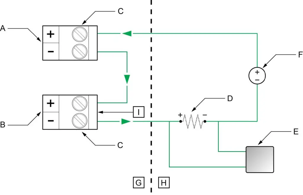
- Use the Micro Motion 5700 Transmitters with Configurable Inputs and Outputs: Installation Manual to install the 5700, except for the wiring instructions for Channels A and D. Instead, wire Channels A and D using one of the following power options:
- Channel A active (internal) power and Channel D passive (external) power
- Channel A passive (external) power and Channel D passive (external) power
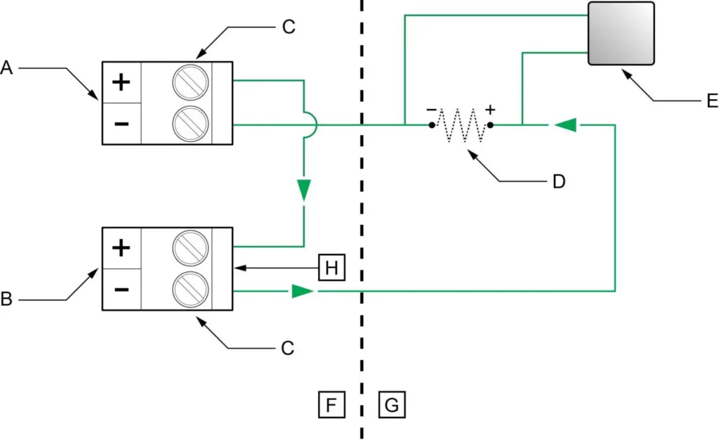
Figure 2-1: Channel A active (internal) and Channel D passive (external) power
- A. Channel A mA output
- B. Channel D mA input
- C. Terminals
- D. 820 ohm maximum loop resistance including 100 ohms (H) for mA input (250–600 ohm for HART communications)
- E. Signal device
- F. Terminal compartment
- G. External to the 5700
- H. 100 ohm input resistance
- Figure 2-2: Channel A passive (external) and Channel D passive (external) power
- A. Channel A mA output
- B. Channel D mA input
- C. Terminals
- D. Maximum loop resistance including 100 ohms (I) for mA input — see Figure 2-3.
- E. Signal device
- F. 5–30 VDC (maximum)
- G. Terminal compartment
- H. External to the 5700
- I. 100 ohm input resistance
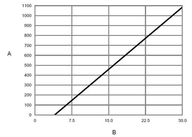
- Figure 2-3: Externally-powered mA/HART output: maximum loop resistance
- A. Maximum resistance (Ω)
- B. External supply voltage (V)
Note
The calculation for loop resistance must include 100 ohms for the mA Input.
- Verify that the following features are licensed: SIL, ChA, ChD.
Note
If SIL is not licensed, see Install the SIL license key. - Verify that Channel D is configured as follows:
Channel D setting Option Channel Type mA Input Power Source External (Passive) mA Input Assignment Loop Current - Verify all safety parameters:
- a) Verify that all appropriate flow and density calibration parameters are set (FCF, K1, K2, D1, D2, and DT).
- b) Verify that the Lower Range Value (LRV) and the Upper Range Value (URV) for Channel A mA Output 1 is configured.
- c) Verify that the appropriate measurement units are configured (mass flow, volume flow, density, and temperature).
- d) Verify that the HART Primary Variable (PV) is assigned to Channel A mA Output.
- e) Verify that the appropriate low flow cutoff parameter is configured.
- f) Verify that the appropriate damping values are configured – such as flow, density, temperature, and added damping.
- g) Verify that the mA Output Fault Action is set to Upscale or Downscale.
Set up a 5700 with intrinsically safe outputs
Procedure
- Use the Micro Motion 5700 Transmitters with Intrinsically Safe Outputs: Installation Manual to mount the transmitter and install the sensor wiring.
- Wire the Channel A passive (external) power to the appropriate output terminal and pins.
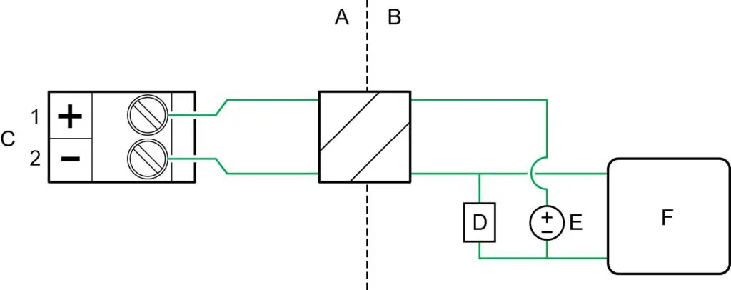
- Figure 2-4: Channel A mA/HART output wiring
- A. Hazardous area
- B. Non-hazardous area
- C. mA/HART output
- D. 250–600 Ω resistance
- E. 24V nominal
- F. HART device
- Figure 2-5: Channel A mA/HART supply voltage and loop resistance
- A. Total loop resistance Rmax (including barrier)
- B. Supply voltage VDC (volts)
- C. Operating region with HART
- D. Operating region without HART (includes the C range)
- Figure 2-4: Channel A mA/HART output wiring
- Verify that the following features are licensed: SIL and ChA.
Note
If SIL is not licensed, see Install the SIL license key. - Verify all safety parameters:
- a) Verify that all appropriate flow and density calibration parameters are set (FCF, K1, K2, D1, D2, and DT).
- b) Verify that the Lower Range Value (LRV) and the Upper Range Value (URV) for Channel A mA output 1 is configured.
- c) Verify that the appropriate measurement units are configured (mass flow, volume flow, density, and temperature).
- d) Verify that the HART Primary Variable (PV) is assigned to Channel A mA Output.
- e) Verify that the appropriate low flow cutoff parameter is configured.
- f) Verify that the appropriate damping values are configured – such as flow, density, temperature, and added damping.
- g) Verify that the mA Output Fault Action is set to Upscale or Downscale.
Diagnostics
Diagnostics for a 5700 with configurable outputs
The SIL license enables a mA Output to mA Input comparison diagnostic.
If the difference between the programmed mA Output and the actual mA Input exceeds
0.2 mA, an Electronics Failed alert becomes active and all analog outputs will be turned off (outputs all to zero) within 5 minutes. The alert shows up as:
| On the display as: | Verification of mAO1 Failed |
| On ProLink III as: | mAO Verification Failed |
After 5 minutes, the outputs are turned back on, and the mA Output to mA Input comparison check is performed again. If the alert was due to a transient condition, since cleared, the transmitter will resume normal operations. If the alert was due to a component failure, the alert will remain active and the outputs will turn off again.
Note
The mA Output to mA Input comparison diagnostic is disabled for the first 5 minutes after the transmitter is powered up. This allows time to verify correct wiring and operation of the ChA-ChD mA Output with mA Input loopback.
Diagnostics for a 5700 with intrinsically safe outputs
The SIL license enables a mA Output to internal mA Readback comparison diagnostic.
If the difference between the programmed mA Output and the actual internal mA Readback exceeds 0.2 mA, an Electronics Failed alert becomes active and all analog outputs will be turned off (outputs all to fault state) within 5 minutes. The alert shows up as:
| On the display as: | Verification of mAO1 Failed |
| On ProLink III as: | mAO Verification Failed |
After 5 minutes, the outputs are turned back on, and the mA Output to internal mA Readback comparison check is performed again. If the alert was due to a transient condition, since cleared, the transmitter will resume normal operations. If the alert was due to a component failure, the alert will remain active and the outputs will turn off again.
Note
The mA Output to mA Readback comparison diagnostic is disabled for the first 5 minutes after the transmitter is powered up. This allows time to verify correct wiring and operation of the ChA mA Output with internal mA Readback.
Enable or disable software write-protection
| Display | Use the mechanical switch on the display. |
| ProLink III | Device Tools → Configuration → Write-Protection |
When enabled, Write-Protection prevents changes to the transmitter configuration. You can perform all other functions, and you can view the transmitter configuration parameters.
Note
The write protection setting via software methods (such as ProLink III) is available only on transmitters without a display.
For transmitters with a display, write protection is available only using the lock switch on the display.![]()
Write-protecting the transmitter primarily prevents accidental changes to configuration, not intentional changes. Any user who can make changes to the configuration can disable write protection.
Upgrade the transmitter firmware
You can upgrade the transmitter firmware to stay current with development and to take advantage of any new features.
Using a USB drive with the display
You can upgrade the transmitter firmware to stay current with development and to take advantage of any new features.
Prerequisites
You must have the firmware upgrade files provided by Micro Motion.
The service port must be enabled. It is enabled by default. However, if you need to enable it, choose Menu → Configuration → Security and set Service Port to On.
Procedure
- Copy the folder containing the firmware upgrade files to a USB drive.
- Open the wiring compartment and insert the USB drive into the service port.
WARNING
If the transmitter is in a hazardous area, do not remove the housing cover while the transmitter is powered up. Failure to follow these instructions can cause an explosion resulting in injury or death. - Follow the prompts once the transmitter recognizes the USB drive.
- Select USB Drive –> Transmitter.
- Select Update Device Software.
- Select the firmware upgrade folder and follow the prompts.
Note
If required, the transmitter upgrade procedure automatically includes an upgrade to the core processor software.
If you chose to reboot the transmitter at a later date, you can reboot it from the menu, or you can power-cycle it. - Verify the transmitter configuration and all safety parameters.
- Enable write-protection.
Using the USB-C service port and ProLink III
You can upgrade the transmitter firmware to stay current with development and to take advantage of any new features.
WARNING
If the transmitter is in a hazardous area, do not remove the housing cover while the transmitter is powered up. Failure to follow these instructions can cause an explosion resulting in injury or death.
Prerequisites
You must have the firmware upgrade files provided by Emerson.
Procedure
- Choose Device Tools → Transmitter Software Update.
- Navigate to the folder containing the firmware upgrade files.
- Select Update.
If you chose to reboot the transmitter at a later date, you can reboot it from the display, or you can power-cycle it. - Verify the transmitter configuration and all safety parameters.
- Enable write-protection.
Replace equipment
If you need to replace hardware, purchase all spare parts from Emerson.
You cannot use user-supplied components on any Emerson printed circuit assemblies.
Procedure
- Replace the hardware.
- Verify the transmitter configuration and all safety parameters.
- Enable write protection.
Install the SIL license key
Use this procedure if the license key was purchased after shipment.
Important
If you added a SIL license key to a meter that was originally installed for a different function, note that the expected meter lifetime starts at the time of the original installation and commissioning. Meter lifetime and all SIS calculations should include total meter operational time.
Always perform Proof tests before placing the meter online.
Note
Smart Meter Verification is the only add on option that is compatible with the SIL license.
Prerequisites
Obtain the SIL license key from your local service office by requesting the model code: LICKEY5700SI.
Note
After you obtain the license key, manually enter the license key using the display, ProLink III, or a field communicator.
Procedure
- To install a license using the display:
- a) Choose Menu → Service Tools → License Manager.
Depending on the type of license key provided, choose either Enter Permanent License or Enter Trial License. - b) Use the arrow keys to enter the license key.
- a) Choose Menu → Service Tools → License Manager.
- To install a license using ProLink III:
- a) Open the license file.
- b) Choose Device Tools → Configuration → Feature License.
- c) Copy the license from the file to the appropriate License Key field.
- d) Select Apply.
- To install a license using a field communicator:
- a) Choose Overview → Device Information → Licenses → Upload License.
- b) Select the license feature to upload, Permanent Feature or Temporary Feature.
- c) Write the license key.
- Use the following menu structures to verify that the license has been installed.
Display Menu → Service Tools → License Manager ProLink III Device Tools → Configuration → Feature License Field communicator Overview → Device Information → Licenses The features supported by the new license are displayed.
Proof tests
Proof tests detect transmitter failures that are not detected by transmitter diagnostics —mainly undetected failures that prevent the Safety Instrumented Function from performing correctly.
The frequency of proof testing, or the proof test interval, is determined by reliability calculations for your transmitter model’s Safety Instrumented Functions.
The proof tests must be performed at least as frequently as specified in the calculation to maintain the required Safety Instrumented Function integrity.
Proof test options
The Coriolis flow meter with a 5700 transmitter has three proof tests you can use to detect failures.
Proof tests can be performed using the display, ProLink III, or a field communicator. Table 3-1: Proof test options
| Device | Proof test | Description | DU failure detection |
| 5700R with standard core processor | 1 | • mA Output min-to-max test
• Checking for alarms • Checking configuration |
50% |
| 1 and 3 | • mA Output min-to-max test
• Checking for alarms • Checking configuration • Calibration against primary standard |
99% | |
| • 5700I
• 5700C • 5700R with enhanced core processor |
1 | • mA Output min-to-max test
• Checking for alarms • Checking configuration |
50% |
| 1 and 3 | • mA Output min-to-max test
• Checking for alarms • Checking configuration • Calibration against primary standard |
99% |
| Device | Proof test | Description | DU failure detection |
| 2 | • mA Output min-to-max test
• Checking for alarms • Checking configuration • Meter verification • Verification of onboard temperature measurement • Test for soft errors in RAM |
91% | |
| 2 and 3 | • mA Output min-to-max test
• Checking for alarms • Checking configuration • Meter verification • Verification of onboard temperature measurement • Test for soft errors in RAM • Calibration against primary standard |
99% |
Proof test 1
Proof test 1 is recommended for all SIL-approved 5700 models.
Prerequisites
This procedure assumes that you are familiar with plant procedures. For details on how to do any of the following steps, see the appropriate 5700 configuration and use manual.
Procedure
- Take appropriate action to avoid a false trip by electronically bypassing the safety Programmable Logic Controller (PLC).
Important
Ensure alternate means are in place to maintain the process in a safe state.
Example
Use Management of Change procedures to override the safety PLC function. - Disable write-protection.
- Using an external device such as a fluke meter, test the mA Output by setting each mA Output to the Fault Level specified for Upscale. Verify that the mA current reaches that value, or use the default value (22mA).
This step tests for compliance voltage problems, such as low voltage on the loop power supply, or increased wiring resistance. - Using an external device such as a fluke meter, test the mA Output by setting each mA Output to the Fault Level specified for Downscale. Verify that the mA current reaches that value, or use the default value.
Option Description 2.0 mA Default for a 5700 with configurable outputs 3.2 mA Default for a 5700 with intrinsically safe outputs This step tests for possible failures related to quiescent current.
- Verify that the transmitter does not display alarms or warnings.
- Verify all safety-critical configuration parameters.
- Restore the loop to full operation.
- Enable write-protection.
- Remove the bypass from the safety PLC, or otherwise restore normal operation.
- Document the results of this proof test as part of your plant safety management procedures.
Proof test 2
Proof test 2 is recommended for an SIL-approved 5700 with the integrated core processor (5700I / 5700C) or the enhanced core processor (5700R).
Prerequisites
This procedure assumes that you are familiar with plant procedures. For details on how to do any of the following steps, see the appropriate 5700 configuration and use manual.
Procedure
- Take appropriate action to avoid a false trip by electronically bypassing the safety Programmable Logic Controller (PLC).
Important
Ensure alternate means are in place to maintain the process in a safe state.
Example
Use Management of Change procedures to override the safety PLC function. - Disable write-protection.
- Using an external device such as a fluke meter, test the mA Output by setting each mA Output to the Fault Level specified for Upscale. Verify that the mA current reaches that value, or use the default value (22mA).
This step tests for compliance voltage problems, such as low voltage on the loop power supply, or increased wiring resistance. - Using an external device such as a fluke meter, test the mA Output by setting each mA Output to the Fault Level specified for Downscale. Verify that the mA current reaches that value, or use the default value.
Option Description 2.0 mA Default for a 5700 with configurable outputs 3.2 mA Default for a 5700 with intrinsically safe outputs This step tests for possible failures related to quiescent current.
- Read the sensor temperature value. Compare it to the process temperature, and verify that this is a reasonable reading.
- Power cycle the transmitter. Wait approximately 30 seconds for the flow meter to return to normal operation.
- Run a meter verification test.
- Verify that the transmitter does not display alarms or warnings.
- Verify all safety-critical configuration parameters.
- Restore the loop to full operation.
- Enable write-protection.
- Remove the bypass from the safety PLC, or otherwise restore normal operation.
- Document the results of this proof test as part of your plant safety management procedures.
Proof test 3
Proof test 3 is recommended for all SIL-approved 5700 models.
Procedure
Perform a full calibration against a primary standard.
Note
The meter verification procedure and the onboard temperature verification tests are incorporated into a full calibration.
Operating constraints
Reliability data
The 5700 transmitter:
- Has a specified safety deviation of 2%. Internal component failures are listed in the device failure rate if they will cause an error of 2% or greater.
- Reports an internal failure within 5 minutes of fault occurrence – worst case scenario.
- Generates a valid signal within 30 seconds of a power-on startup.
FMEDA report
The Failure Mode, Effects, and Diagnostics Analysis (FMEDA) report is used to calculate the failure rate. A FMEDA report for a 5700 transmitter contains:
- All failure rates and failure modes
- Common cause factors for applications with redundant devices that should be included in reliability calculations
- The expected lifetime of your flow meter and transmitter, as the reliability calculations are valid only for the lifetime of the equipment; useful flow meter lifetime is 10 years —see the FMEDA report for details
Obtain a FMEDA report from Emerson.com.
Environmental and application limits
See the sensor and 5700 product data sheets for environmental and application limits.
Using the 5700 transmitter outside environmental or application limits invalidates the reliability data in the FMEDA report.
Report failures
Procedure
If you have detected any failures that compromise safety, contact the Emerson product safety officer.
Contact the product safety officer through customer service. Customer service is available 24 hours a day, seven days a week. Contact information is located at the front of this manual.
For more information: www.emerson.com ©2022 Micro Motion, Inc. All rights reserved.
The Emerson logo is a trademark and service mark of Emerson Electric Co. Micro Motion, ELITE, ProLink, MVD and MVD Direct Connect marks are marks of one of the Emerson Automation Solutions family of companies. All other marks are property of their respective owners.
![]()
SENSI™ THERMOSTAT
Navigation & Scheduling guide
Models: 1F95U-42WF series, ST75 series, NH-AWIFI, OH-AWIFI, 1F87U-42WF, ST55
Version: January 2020
© 2020 Emerson Electric Co. All rights reserved
R-5031
App navigation 3
Scheduling 5
Sensi™ smart Thermostats | APP NAVIGATION & SCHEDULING 2
APP NAVIGATION
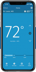
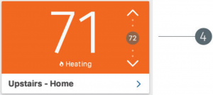
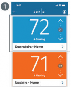
The Sensi app allows you to remotely control your thermostat when connected to your Wi-Fi network. After installing your Sensi thermostat, your app dashboard will look like what you see below. You can edit account information, add another thermostat and quickly adjust the temperature on any thermostat on your account. To edit individual thermostat settings or features, select that thermostat name.
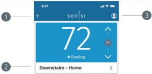
- ADD DEVICE
Tap the plus (+) sign to add an additional thermostat. You can also use the + sign to reconnect Sensi to Wi-Fi - THERMOSTAT NAME
Tap your thermostat name to go into the main control screen for that individual thermostat. - ACCOUNT INFORMATION
Edit your email address and password, opt in or out of thermostat alerts, access our help center, leave feedback or log out. (This will be 3 vertical dots on Androids.) - TEMPERATURE CONTROL
Check your current set temperature and quickly adjust it using the up and down arrows.
Sensi™ smart Thermostats | APP NAVIGATION & SCHEDULING 3
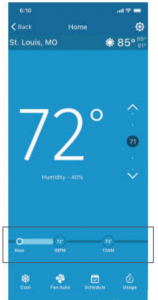
APP NAVIGATION
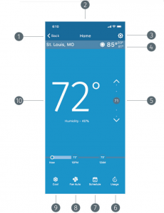
- BACK TO DASHBOARD
- THERMOSTAT NAME
- SETTINGS
Access all the advanced settings and features including AC Protection, Temperature and Humidity Offset, Keypad Lockout and Cycle Rate. You can also adjust the temperature scale and see some statistics about your thermostat - WEATHER
Local weather based on the location information you provided when you registered. - SET TEMPERATURE
- USAGE DATA
Here you can see how many minutes and hours your system has run. - SCHEDULING OPTIONS
Turn on and edit a schedule or try geofencing. - FAN MODE OPTIONS
You can toggle circulating fan from here. - SYSTEM MODE
Change your system mode as needed. - ROOM TEMPERATURE
Sensi™ smart Thermostats | APP NAVIGATION & SCHEDULING 4
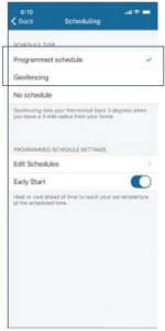
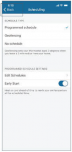
SCHEDULING
Scheduling can save you time and money by automatically following a set schedule you determine. Each individual thermostat can have its own schedule. The following steps will walk you through how to set up, edit and turn on a schedule.
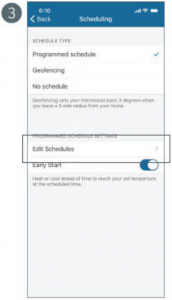
If a programmed schedule doesn’t fit your lifestyle, you also have the option to turn on geofencing (temperature control based on whether you’re home or not). The geofencing feature is located under the scheduling tab. For all information on geofencing, visit the support section of emerson.sensi.com and search “geofencing.”
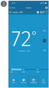
- Select the thermostat you want to edit.
- Tap “Schedule”.
- Tap “Edit Schedules” to view all of your schedules.
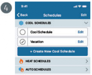
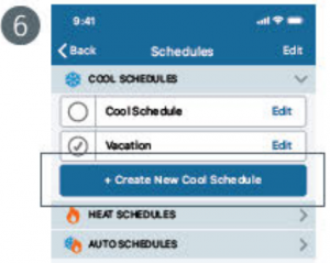
- Your schedules are organized by system mode. You can choose to edit an existing schedule in a mode or create a new schedule. For example: Create a new cool schedule or edit your vacation schedule.
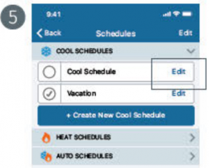
Note: The schedule that has a check mark next to it is the active schedule to run in that mode. You must have one active schedule per system mode whether you’re using it or not. - To edit an existing schedule, select the “Edit” option to the right of that schedule
- To create a new schedule, tap the “+ Create a New Cool Schedule” button.
Sensi™ smart Thermostats | APP NAVIGATION & SCHEDULING 5
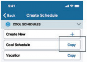
7. When creating a new schedule, you can begin by first copying an existing schedule. To do this, select the “Copy” option to the right of that schedule.
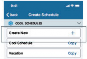
8. To create a new schedule from scratch, tap “Create new” at the top.
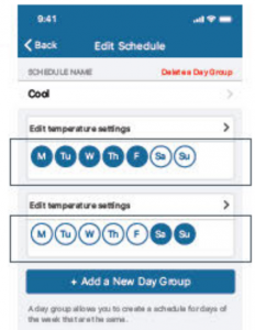
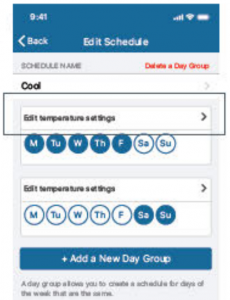
9. At the first editing schedule, you can group days that you want to have the same time and temperature set points. The default day grouping is Monday – Friday, and Saturday — Sunday. You can move the days around by tapping them in the group you want.
For example: If you want to bring Saturday into the Monday – Friday grouping, simply tap the unfilled Saturday circle in the first grouping.
Note: If you want one seven-day schedule, you’ll be left with an empty day group. Use the “Delete a Day Group” option to delete that day group. (If you’re using and Android device, press and hold on “Edit Daily Schedule” for that empty row to delete it)
10. After you’re done sorting the day groupings, tap “Edit temperature settings” to adjust set points.
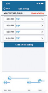
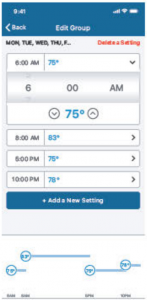
11. Tap on any set point to adjust the set time and temperature.
Note: You can add more set points by tapping on the “+ Add a New Setting” button. You can delete any set points by tapping on the “Delete a Setting” button. (On Android devices, press and hold on any set point to delete it.)
Sensi™ smart Thermostats | APP NAVIGATION & SCHEDULING 6
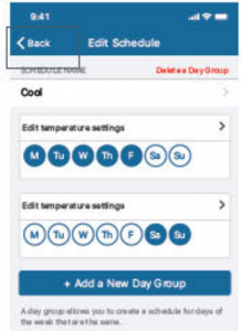
12. When you’re done, tap the arrow in the upper left hand corner to return to the day groupings and edit any other group of days you have. When you’re completely done editing your schedule, make sure you have it selected under the system mode drop down and then tap the arrow in the upper left hand corner to return to the Main Scheduling screen.
13. Make sure you’ve got “Programmed schedule” selected so your Sensi thermostat can run your new schedule.
14. Tap the arrow in the top left hand corner to see a timeline of your set points.

Dixell™ Universal-XR Controller
The Only Replacement Controller You’ll Ever Need
Simplify repair of refrigeration and heating controllers

 By Joe Summers
Product Manager,
Power Electronics &
Integrated Solutions Emerson
from reach-in coolers to deli prep tables to bread proofers, the foodservice industry uses literally thousands of different refrigeration and heating units. It simply isn’t practical for contractors and wholesalers to keep every possible controller model on hand. But when
a controller fails, waiting on a specific replacement can cause costly delays for both the repair service and the customer.
Emerson responded to this common problem by creating the Dixell™ Universal-XR controller. This dual-supply voltage controller is capable of replacing thousands of SKUs, including more than 150 of the most common 32×74 mm format controllers. The most typical applications can be back up and running quickly — often in just a few minutes — regardless of the original make or manufacturer.
The Universal-XR controller is a boon to repair contractors. The unit is stocked at thousands of authorized Emerson wholesalers nationwide, usually at a very competitive cost compared to the controllers it can replace. With Universal-XR units on their trucks, contractors won’t have to waste as much time selecting a specific controller. This saves time for themselves and eliminates downtime for their customers, enabling contractors to
get to their next jobs quicker.
Wholesalers also stand to benefit from our controller. The unit can significantly reduce the number of SKUs they need to keep in stock. They can keep inventories lower — yet still have the right controller for the job available.
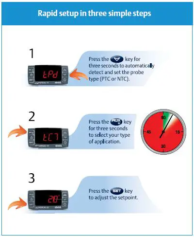
Key benefits of the Universal-XR controller
Quick installation and programming — The Universal-XR controller gives repair contractors a “drop-in” solution that can be configured rapidly in just three simple steps (see “Rapid setup in three simple steps” sidebar).
- Dimensional footprint matches more than 80 percent of the most common controllers on the market.
- Simple wiring setup supports four to eight connections.
- Hot key enables fast and simple programming.
Dual-voltage power supply — The unit is versatile enough to replace commonly used low- and high-voltage controllers.
- Two different terminal blocks give direct connections to 12VAC/DC or 230VAC power supplies. One unit covers both standard voltages.
- Power supply isn’t needed to change voltage in 230VAC configurations.
- 12VAC/DC configurations typically don’t need an electrician to sign off
on the installation.
“Plug and play” functionality — Dixell’s common five-pin connector, which is
similar to a USB device, enables a wide variety of useful applications, including:
- Easy connectivity for downloading parameters, fault history logs and other data.
- Enables custom parameters to be uploaded into the controller.
- Factory reset to default configuration.
- Offers CTL serial connections.
- Allows connections to the cloud or BMS, including the Emerson XWEB300D and XWEB500D EVO web servers for control and alarm management.
Complete system management — The controller manages every aspect of the cooling or heating system.
- Activates and deactivates the compressor, defroster, fan and motors.
- Senses the difference between readings caused by the controlled devices versus issues with wiring.
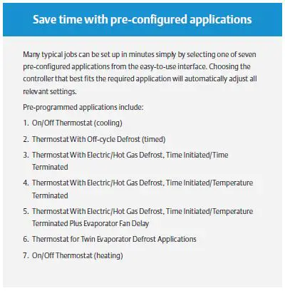
Seven pre-configured applications — Support quick and easy startup. (See the “Save time with pre-configured applications” sidebar.)
- Seven different maps are selectable from the intuitive interface, allowing the most common applications to be set up in just a few minutes.
- Automatically configure up to three probes, four relays and two digital inputs.
Self-learning automatic probe detection — Other controllers are typically limited to just one type of sensor: NTC or PTC. The Universal-XR controller automatically detects which type of sensor is in use and configures itself appropriately.
- Single controller can manage both common types of probes.
- One-touch smart sensing: just press a single button for three seconds and wait for the controller to detect the probes.
- Contractors don’t have to worry that the controller won’t work because of a sensor mismatch or faulty reading.
Simple two-zone/twin evaporator defrost support — Two evaporator probes and specific parameters allow the unit to easily control two different defrost terminations.
- The display alternates between the temperatures of each zone.
- Users can monitor two zones (e.g., produce and ice cream) at a glance.
User-friendly front display — Easily allows users to see what’s going on in the system.
- Intuitive design enables customers to see and understand compressor, defroster, fan and motor activities in a single glance.
- Popular with many users.
By providing easy service replacement for most major controllers, the Universal-XR controller offers an instant replacement solution for nearly every application.
Why keep trying to manage more than 150 separate products when a single controller can take their place?

Want to install the easy way?

Single-Stage Thermostat
 WARNING Failure to follow and read all instructions carefully before installing or operating this control could cause personal injury and/or property damage.
1. PREPARATIONS
1.1 Check package contents
This package should contain the following items: 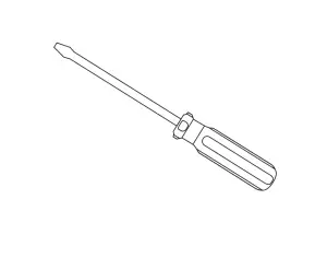
- Thermostat
- Mounting screws and wall anchors (x2)
- 2 AAA batteries
- Terminal wire label stickers
- Installation instructions
1.2 Gather tools
Required tools:
- Flat-head Screwdriver □ Small pliers (needle-nose) □ Drill with 3/16” (4 mm) bit
Optional tools: - Wire cutters/stripper □ Hammer
2. THERMOSTAT DETAILS
The thermostat buttons and switches
- Raises temperature setting.
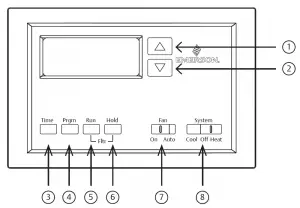
- Lowers temperature setting.
- TIME button.
- PRGM (program) button.
- RUN (run program) button.
- HOLD temperature button.
- FAN switch (ON, AUTO).
- SYSTEM switch (COOL, OFF, HEAT).
3. REMOVING OLD THERMOSTAT
3.1 Turn off power
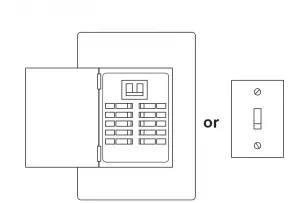
 WORNING To prevent electrical shock and/or equipment damage, disconnect electrical power to the system at the main fuse or circuit breaker box, or by flipping a switch at the air handler. Do not restore power until installation is complete.
To ensure the power to your heating and cooling system has been turned off, try to turn on heating or cooling by changing the temperature on your old thermostat.
3.2 Remove the old thermostat cover
Remove the old thermostat’s front cover from the wall base. Some covers pull off easily, while others may need to be removed by prying the cover off with a screwdriver.
WORNING Your old thermostat may have a sealed glass tube containing mercury. Be careful not to damage the tube or dispose of the tube in your trash.
For safe disposal information, please see Mercury Notice on page 43.
3.3 Label wires
Tip: Taking a picture with a camera or smartphone can help you not only remember how wires are connected to the terminals, but can also ensure that you label your wires correctly.
Using your screwdriver, carefully unscrew one wire at a time from the terminal block and attach the corresponding wire label sticker.
Please note that not all terminals may be used, and that there’s no standard color code for thermostat wires, so your wire colors may vary. For your reference, we’ve included a terminal label reference chart on page 7 to help you connect the wires in your old thermostat to your new thermostat in case you get stuck.
Terminal labeling reference chart
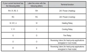
3.4 Identify jumper wire
| On your old thermostat, if… | Then, on your new thermostat… |
| Terminal RC and RH are connected with a jumper wire |
Leave the jumper wire in its place |
| There’s only one R wire (RC, RH, R or R5) coming out of the wall | Leave the jumper wire in its place |
| Terminal RC and RH (or 5 or R5) are NOT connected by a jumper wire | Remove the jumper wire between RC and RH |
For terminal Y and W:
If you have a heat pump with reversing valve, connect Y and W with a jumper wire on your new thermostat.
If you need help with labeling and wiring, please contact Customer Support at 877.654.9394 or email
[email protected] — we’re here to help!
3.5 Remove old thermostat base
With all of your wires disconnected and properly labeled, you may now safely remove the thermostat base from your wall.
Tip: Worried about having your wires falling into your wall? Keep the wires secure by wrapping the them around a pencil.
4. MOUNTING AND WIRING YOUR NEW THERMOSTAT
4.1 Install new thermostat base
Mount your new thermostat base using the supplied screws. Drill holes and insert wall anchors to secure the thermostat base to the wall, if necessary.
4.2 Connect wires to corresponding terminal blocks
Match each labeled wire to it’s corresponding terminal on the mounted thermostat base. Insert each labeled wire into the hole of it’s matching terminal, and using the screwdriver, tighten the screw on the terminal block securely.
 CAUTION Take care when securing and routing wires so they do not short to adjacent terminals or rear of thermostat. Personal injury and/or property damage may occur.
4.3 Set switch and advanced wiring
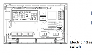 If you have either a gas or oil furnace, set the switch to GAS.
If you have an electric furnace, set the switch to ELEC.
4.4 Install the batteries and attach front cover
Install the included AAA alkaline batteries and push the front cover on to the thermostat base until it’s secure.
4.5 Turn on power
Turn on your power at the source.
Congratulations! You’ve completed the thermostat installation process
5. CHECK THERMOSTAT OPERATION
Tip: If at any time during testing your system does not operate properly, please contact Customer Support at 877.654.9394 or email [email protected]
5.1 Fan operation
If your system does not have a G terminal connection, skip to 5.2 Heating system.
- Move FAN switch to ON position. The blower should begin to operate.
- Move FAN switch to AUTO position. The blower should stop immediately.
5.2 Heating system
- Move SYSTEM switch to HEAT position. If the heating system has a standing pilot, be sure to light it.
- Press
 to adjust thermostat setting room temperature. The heating system should begin to operate.
 - Press
 to adjust temperature setting below room temperature. The heating system should stop operating.
5.3 Cooling system
CAUTION To prevent compressor and/or property damage, if the outdoor temperature is below 50°, DO NOT operate the cooling system
- Move SYSTEM switch to COOL position.
- Press to adjust thermostat setting below room temperature. The blower should come on immediately on high speed, followed by bold air circulation.
- Press to adjust temperature setting above room temperature. The cooling system should stop operating.
5.4 Typical wiring diagrams
6. PROGRAMMING YOUR THERMOSTAT
Before you begin programming your thermostat, you should be familiar with its features and with the display and the location and operation of the thermostat buttons. Your thermostat consists of two parts: the thermostat cover and the base. To remove the cover, pull it straight out from the base. To replace the cover, line up the cover with the base and press until the cover snaps onto the base.
6.1 The thermostat buttons and switches
- Raises temperature setting.
- Lowers temperature setting.
- TIME button.
- PRGM (program) button.
- RUN (run program) button.
- HOLD temperature button.
- FAN switch (ON, AUTO).
- SYSTEM switch (COOL, OFF, HEAT).
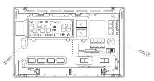
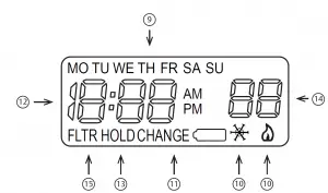
6.2 The display
- Indicates day of the week.
- Flame icon () is displayed when the SYSTEM switch is in the HEAT position. Snowflake icon ()is displayed (non-fl ashing) when the SYSTEM switch is in the COOL position. Snowflake is displayed (fl ashing) if the thermostat is in lockout mode to prevent the
compressor from cycling too quickly. - Displays “CHANGE ” when the 2 “AAA” batteries are low and should be replaced.
Only “CHANGE ” and “LO” in the minutes field are displayed when batteries are low with no system power. - Alternately displays current time and temperature. Displays “LO” in the minutes field when batteries are low.
- The word “HOLD” is displayed when the thermostat is in the HOLD mode. “HOLD” is displayed fl ashing when the thermostat is in a temporary HOLD Mode.
- Displays currently programmed set temperature (this is blank when SYSTEM switch is
in the OFF position). - Displays “FLTR” when the system has run for the programmed filter time period as a reminder to change or clean your air filter.
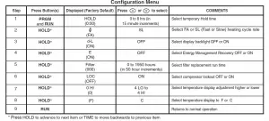
6.3 Configuration menu
The configuration menu allows you to set certain thermostat operating characteristics to your system or personal requirements.
Press RUN to make sure the thermostat is in the run program mode, then press PRGM and RUN at the same time to enter the configuration menu. The display will show the first item in the configuration menu.
The configuration menu table summarizes the configuration options. An explanation of each option follows.
Press HOLD to change to the next menu item or press TIME to go backwards to the previous item in the menu. To exit the menu and return to the program operation, press RUN. If no keys are pressed within fifteen minutes, the thermostat will revert to normal operation.
1. Select Temporary Hold Time – The thermostat can hold any temperature you set it to for the amount of time you select on this option. Your choices are 0:00 to 8:00 hours in 15 minute increments. 0:00 disables the function
Example:
- You have selected 3:00 hours for the Temporary Hold time period.
- With the thermostat set to Heat or Cool, press HOLD for approximately five seconds until HOLD time (3:00 indicating 3 hours) appears as a setting reminder.
- After releasing the button, “HOLD” on the display will blink.
- Use or to set the temperature to your preference. The thermostat will maintain this temperature setting for 3 hours with “HOLD” blinking to remind you it is in Temporary Hold. After 3 hours the thermostat will go back to the program temperature and “HOLD” will no longer blink or display.
2. Select FA or SL (Fast or Slow) Heating Cycle Rate – The FA setting is frequently used for gas, oil or electric heat. The SL setting produces a longer heating cycle which is normally for hot water or steam (hydronic) systems. Both settings produce very accurate temperature control and can be set to your personal preference. FA cycles the system just under 1°F and the SL setting cycles at approximately 1.5°F.
3. Select backlit display – The display backlight improves display contrast in low lighting conditions. Selecting backlight ON will keep the light on for a short period of time after any key is pressed. Selecting OFF will keep the light off.
4. Select Energy Management Recovery OFF or ON – Energy Management Recovery (EMR) causes the
thermostat to start heating or cooling early to make the building temperature reach the program setpoint at the time you specify. Heating will start 5 minutes early for every 1° of temperature required to reach setpoint.
Example:
You select EMR and have your heating programmed to 65° at night and 70° at 7 AM. If the building temperature is 65° the difference between 65° and 70° is 5°. Allowing 5 minutes per degree the thermostat setpoint will change to 70° at 6:35 AM. Cooling allows more time per degree because it takes longer to reach temperature.
5. Select filter replacement run time – The thermostat will display “FLTR” after a set time of operation. This is a reminder to change or clean your air filter. This time can be set from 0 to 1950 hours in 50 hour increments. A selection of 000 will cancel this feature. When “FLTR” is displayed, you can clear it by pressing HOLD and RUN at the same time. This resets the timer and starts counting the hours until the next filter change. Changing the time in the menu also resets the timer.
6. Select Compressor Lockout LOC OFF or ON – Selecting LOC ON will cause the thermostat to wait 5
minutes before turning on the compressor if the heating and cooling system loses power. It will also wait a
minimum of 5 minutes between cooling cycles. This is intended to help protect the compressor from short cycling. Some newer compressors already have a time delay built in and do not require this feature. Your
compressor manufacturer can tell you if the feature is already present in their system. When the compressor time delay occurs it will fl ash the (snowfl ake icon) for about five minutes then turn on the compressor.
7. Select Temperature Display Adjustment 4 LO to 4 HI – Allows you to adjust the room temperature display
+/- 4°. Your thermostat was accurately calibrated at the factory but you have the option to change the display temperature to match your previous thermostat.
8. Select F° or C° Readout – Changes the display readout to Celsius or Fahrenheit as required.
6.4 Operating features
This section contains information about the many features of your new thermostat.
- SIMULTANEOUS HEATING/COOLING PROGRAM STORAGE — When programming, you can enter both your heating and cooling programs at the same time. There is no need to reprogram the thermostat at the beginning of each season.
- TEMPERATURE OVERRIDE — Press or until the display shows your desired temperature.
The thermostat will override current programming and keep the room temperature at the selected temperature
until the next program period begins; then, the thermostat will automatically revert to the program. - HOLD TEMPERATURE — The thermostat can hold any temperature within its range for an indefinite period without reverting to the programmed temperature. To engage this feature, press HOLD button. “HOLD” will be displayed. Then choose the desired temperature by pressing or . The thermostat will hold the room temperature at the selected setting until you press RUN button to start program operation again.
- CONFIGURATION MENU — Allows you to customize certain thermostat options.
6.5 Programming your thermostat
This section will help you plan your thermostat’s program to meet your needs. For maximum comfort and efficiency, keep the following guidelines in mind when planning your program:
- When heating (cooling) your building, program the temperatures to be cooler (warmer) when the building is vacant or during periods of low activity.
- During early morning hours, the need for cooling is usually minimal.
Planning your program
Look at the factory pre-programmed times and temperatures shown in the sample schedule. If this program will suit your needs, simply press the RUN button to begin running the factory preset program.
If you want to change the pre-programmed times and temperatures, follow these steps.
Determine the time periods and temperatures for your weekday and weekend programs. You must program
four periods for both the weekday and weekend program. However, you may use the same heating and cooling temperatures for consecutive time periods. You can choose start times, heating temperatures, and cooling
temperatures independently for both weekday and weekend programs (for example, you may select 5:00 AM and 70° as the weekday 1st period heating start time and temperature, and also choose 7:00 AM and 76° as the weekday 1st period cooling start time and temperature).
SAMPLEHeating/Cooling Schedule Plan (Factory Program)
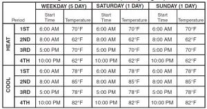
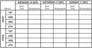
Use the following table to plan your program time periods and the temperatures you want during each period. Fill in the complete table to have a record of your programs.
Heating/Cooling Schedule Plan
Entering your program
Follow these steps to enter the heating and cooling programs you have selected.
Set Current Time and Day
- Press TIME button once. The display will show the hour only.

- Press and hold either or until you reach the correct hour and AM/PM designation (AM begins at midnight; PM begins at noon).
- Press TIME once. The display window will show the minutes only.

- Press and hold either or until you reach the correct minutes.
- Press TIME once. The display will show the day of the week.
- Press or until you reach the current day of the week.
- Press RUN once. The display will show the correct time and room temperature alternately.
Set Heating Program
- Move the SYSTEM switch to HEAT.
- Press PRGM once. “MO TU W TH FR” (indicating weekday program) will appear in the display. Also displayed are the currently programmed start time for the 1st heating period and the currently programmed temperature (fl ashing).
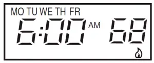 This display window shows that for the 1st weekday period, the start time is 6:00 AM, and 68° is the
programmed temperature (this example refl ects factory preprogramming). - Press or to change the displayed temperature to your selected temperature for the 1st heating program period.
- Press TIME once (the programmed time will fl ash). Press or until your desired time appears. The time will change in 15 minute increments. When your selected time is displayed, press TIME again to return to the change temperature mode.
- Press PRGM once. The currently programmed start time and setpoint temperature for the 2nd heating program period will appear.
- Repeat steps 3 and 4 to select the start time and heating temperature for the 2nd heating program period.
- Repeat steps 3 through 5 for the 3rd and 4th heating program periods. Weekday heating programs are now complete.
- Press PRGM once. “SA” (indicating Saturday program) will appear in the display, along with the start time for the 1st heating period and the currently programmed temperature.
- Repeat steps 3 through 7 to complete Saturday heating programming.
- Press PRGM once. “SU” (indicating Sunday program) will appear in the display, along with the start time for the 1st heating period and the currently programmed temperature.
- Repeat steps 3 through 7 to complete Sunday heating programming.
- When you have completed entering your heating program, press RUN.
Set Cooling Program
CAUTION If the outside temperature is below 50° F, disconnect power to the cooling system before programming. Energizing the air conditioner compressor during cold weather may cause personal injury or property damage.
- Move SYSTEM switch to COOL position.
- To set your cooling program, follow the same procedure as setting your heating program, but use your selected cooling times and temperatures.
Check your programming
Follow these steps to check your thermostat programming one final time before beginning thermostat operation.
- Move SYSTEM switch to HEAT position.
- Press PRGM to view the 1st weekday heating period time and temperature. Each time you press PRGM, the next heating period time and temperature will be displayed in sequence for weekday, then weekend program periods (you may change any time or temperature during this procedure).
- Press RUN.
- Move SYSTEM switch to COOL position.
- Repeat step 2 to check cooling program.
- Move SYSTEM switch to HEAT or COOL and press RUN to begin program operation.
CONGRATULATIONS! Your new thermostat is now programmed.
7. SPECIFICATIONS
ELECTRICAL DATA
Electrical Rating:
8 to 30 VAC 50/60 Hz. or D.C.
0.05 to 1.0 Amps (Load per terminal)
1.5 Amps Maximum Total Load (All terminals combined)
THERMAL DATA
Setpoint Temperature Range: 45°F to 90°F (7°C to 32°C)
Operating Ambient Temperature Range: 32°F to 105°F
Operating Humidity Range: 0 to 90% RH (non-condensing)
Shipping Temperature Range: -4°F to 149°F
APPLICATIONS
For use with:
- Standard heat/cool or heat only systems
- Electric heat systems
- Gas or oil fired systems
- Gas systems with intermittent ignition devices (I.I.D.) and/or vent dampers
- Hydronic (hot water or steam) systems
- Single-stage heat pump systems (no auxiliary heat)
- Millivolt
DO NOT USE WITH:
- Multi-stage systems
- Systems exceeding 30 VAC and 1.5 amps
- 3-wire zoned hydronic heating systems
8. TROUBLESHOOTING
Reset Operation
If a voltage spike or static discharge blanks out the display or causes erratic thermostat operation you can reset the thermostat by pressing , , and TIME at the same time. This also resets the factory defaults to the configuration menu and program. If the thermostat has power, has been reset and still does not function correctly contact your heating/cooling ser-vice person or place of purchase.
Batteries
For optimum performance, we recommend replacing batteries once a year with fresh “AAA” alkaline batteries.
| Symptom | Possible Cause | Corrective Action |
| No Heat/No Cool/No Fan (common problems) |
|
Replace fuse or reset breaker. Turn switch to ON. Replace door panel in proper position to engage safety interlock or door switch. |
| No Cool |
|
Set SYSTEM Switch to COOL and lower setpoint temperature below room temperature. Verify thermostat and system wires are securely attached. Same procedure as diagnostic for No Heat condition except set the thermostat to COOL and lower the setpoint below the room temperature. There may be up to a five minute delay before the thermostat clicks in Cooling. |
| Symptom | Possible Cause | Corrective Action |
| No Heat |
|
Re-light pilot. Set SYSTEM Switch to HEAT and raise setpoint temperature above room temperature. Verify thermostat and system wires are securely attached. Many furnaces have safety devices that shutdown when a lock-out condition occurs. If the heat works intermittently contact the furnace manufacturer or local service person for assistance. Diagnostic: Set SYSTEM Switch to HEAT and raise the setpoint above room temperature. Within a few seconds the thermostat should make a soft click sound. This sound usually indicates the thermostat is operating properly. If the thermostat does not click, try the reset operation listed below. If the thermostat does not click after being reset contact your heating and cooling service person or place of purchase for a replacement. If the thermostat clicks, contact the furnace manufacturer or a service person to verify the heating is operating correctly. |
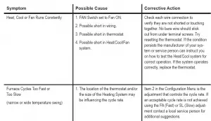
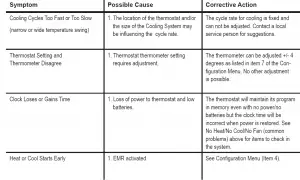
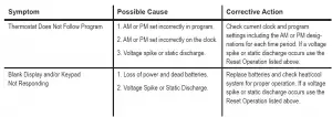
CONTACT US
Customer support: 877.654.9394 or [email protected]
MERCURY NOTICE
This product does not contain mercury. However, this product may replace a product that contains mercury.
Mercury and products containing mercury must not be discarded in household trash.
Refer to thermostat-recycle.org for location to send product containing mercury.
FOR CALIFORNIA RESIDENTS
Warning: This product contains a chemical known to the state of California to cause cancer and birth defects and other reproductive harm.
]]>Relays and Transformers 90-112 Thru 90-130 Fan Control Center Specifications Manual
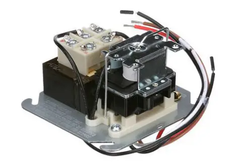
Transformer and relay combination for easy installation on a 4″ X 4″ junction box.
FEATURES
- Line voltage connections pre-wired
- Energy limiting Class II transformer design
- Color coded pre-stripped leads
- Low voltage connections on terminal board
SPECIFICATIONS
UR/CUR File Number …………………………………………………………………………………….E73641
REPLACEMENT RELAY FOR FAN CONTROL CENTER

90-112 THRU 90-130 FAN CONTROL CENTER
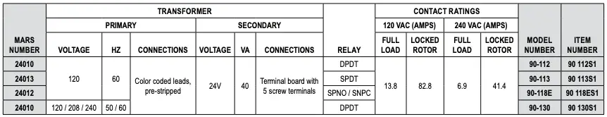
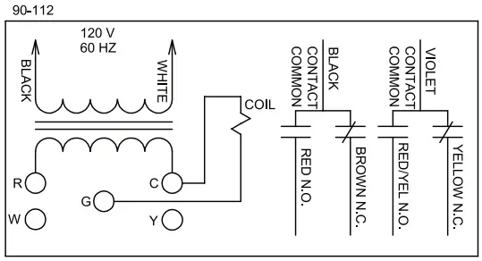
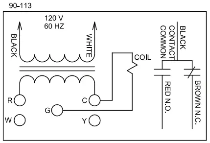
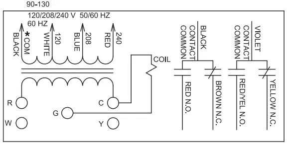
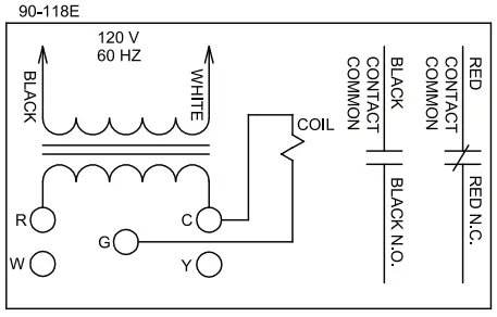
When the fan relay transformer is energized and the thermostat completes the connection from R to G the fan relay coil energizes. Line voltage power applied to contact common path travels to selected blower speed tap. Additional terminal Y and W are isolated tie point terminals to connect thermostat wiring to compressor and furnace (if required).
NOTE: Record the lead wire color with its corresponding terminal for future reference. Unused transformer input leads must be insulated.
* Black is common with respect to transformer winding, not external circuit.
]]>![]()
1F83C-11NP (Non-Programmable)
Installation and Operating Instructions
Single Stage Thermostat
Battery Powered or Hardwired with Common
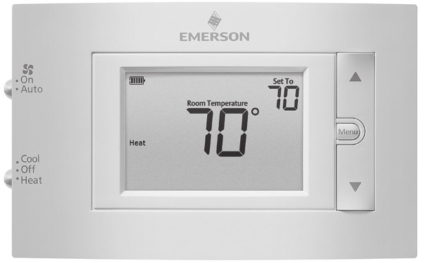
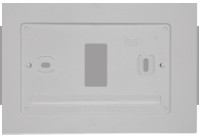
Optional Accessory: Wall
Cover-Up Plate F61-2663,
6 3/4” W x 4 1/2” H
| Thermostat Applications | Maximum Stages Heat/Cool |
| Conventional Gas, Oil, Electric (mV and 24V), Heat Only, Cool Only, or Heat/ Cool Systems |
1/1 |
| Heat Pump (air source or geothermal) with no Aux. Heat |
1/1 |
MERCURY NOTICE: This product does not contain mercury. However, this product may replace a product that contains mercury. Mercury and products containing mercury must not be discarded in household trash. Refer to www.thermostat-recycle.org for information on disposing of products containing mercury.
SPECIFICATIONS
Electrical Rating:
Battery Power ………………………………. mV to 30 VAC, NEC Class II, 50/60 Hz
Input-Hardwire ……………………………… 20 to 30 VAC, NEC Class II, 50/60 Hz
Terminal Load …………………………………… 1.0 A per terminal, 1.5A maximum all terminals combined
Setpoint Range …………………………………. 45° to 99° F (7° to 37° C)
Rated Differentials: Fast Med Slow
Heat (@ 6°F/ Hr) ……………………………. 0.5°F 0.75°F 1.9°F
Cool (@ 6°F/ Hr) ……………………………. 0.9°F 1.2°F 1.7°F
Operating Ambient ……………………………. 32°F to +105°F (0° to +41°C)
Display Temperature Range ………………….. 32°F to +99°F (0 to 37°C)
Operating Humidity …………………………… 90% non-condensing max
Shipping Temperature Range ………………. -20°F to + 150°F (-29° to +65°C)
Thermostat Dimensions ……………………… 3-3/4” H x 6” W x 1-1/8” D
emersonthermostats.com
white-rodgers.com
PART NO. 37-7479001
Replaces 37-7479C
1728
THERMOSTAT INSTALLATION
WIRING
Refer to equipment manufacturer’s instructions for specific system wiring information. After wiring, see INSTALLER MENU for proper thermostat configuration. The wiring table shown is for typical systems and describes the thermostat terminal functions.
| Terminal Designations | Terminal Function |
| RC* | Power for Cooling |
| RH* | Power for Heating |
| 0/B | Changeover Terminal-Energized in Heat (B) or Cool (0) for Heat Pump or Damper Systems |
| y** | Cooling Relay |
| G | Fan Relay |
| W** | Heating Relay |
| C | Common wire for 24V (optional with batteries) |
*When both RC and RH wires are present, cut RC/RH jumper (see next page).
**For heat pump systems, add a jumper wire to connect terminals Y and W
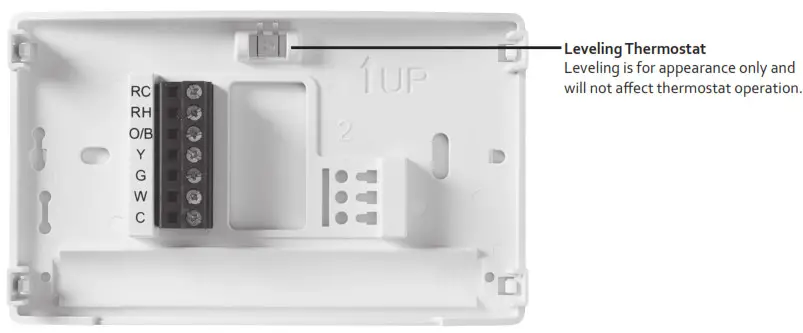
Precautions
- Do not exceed the specification ratings.
- All wiring must conform to local and national electrical codes and ordinances.
- This control is a precision instrument and should be handled carefully. Rough handling or distorting components could cause the control to malfunction.
 WARNING
Do not use on circuits exceeding specified voltage. Higher voltage will damage control and could
cause shock or fire hazard.
Do not short out terminals on gas valve or primary control to test. Short or incorrect wiring will burn
out the thermostat and could cause personal injury and/or property damage.
CAUTION
To prevent electrical shock and/or equipment damage, disconnect electrical power to the system, at main fuse or circuit breaker box,until installation is complete.
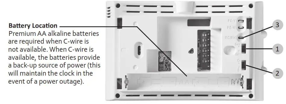
1.) Gas/Elec Switch
If the system is a heat pump or electric furnace, the GAS/ELEC Switch must be set to Elec. If your system is a gas or oil furnace, the switch must be set to Gas.
2.) O/B Terminal Switch
The O/B switch on this thermostat is factory set to the O position. This will accommodate the majority of heat pump applications, which require the changeover relay to be energized in Cool. If the heat pump is installed requires a B terminal, to energize the changeover relay in Heat, the O/B switch must be moved to the B position.
3.) RC/RH Jumper Wire
This thermostat electrically connects the RC and RH terminals so a jumper wire is not required. If the application provides a separate wire for RC and RH, clip the RC/RH jumper. This will isolate both terminals so they can be independently used.
INSTALLER MENU
To prevent changes that may affect system performance, this thermostat has an INSTALLER’S MENU and a USER MENU. The INSTALLER’S MENU provides access to every option, while the USER MENU provides access to items that will not affect system performance. To access the INSTALLER’S MENU press the Menu button for 8 seconds. The display will show item 30 in the table below. Use Next and Back to navigate through menu items. Press ![]() or
or ![]() change a menu setting.
change a menu setting.
| Installer’s Menu # (Hold Menu 8 Seconds) |
Description | Default Setting (flashing icons) |
Settings (Press A 0TV) |
 |
Heat Cycle Rate (how often the heat will turn on) | MEd | SLO — slow MEd — medium FAS — fast |
 |
Cool Cycle Rate (how often the cooling will turn on) | MEd | SLO — slow MEd — medium FAS — fast |
 |
Compressor Lockout (protects the compressor from short cycling) | OFF | On — 5-minute display OFF — no delay |
65 |
Maximum Heat Limit (maximum set point for heat mode) |
99 | 47 to 99 |
66 |
Minimum Cool Limit (minimum setpoint for cool mode) |
45 | 45 to 97 |
(Installer Menu continued on next page)
INSTALLER MENU (C0ntinued)
| Installer’s Menu # (Hold Menu 8 Seconds) |
Description | Default Setting (flashing icons) |
Settings |
| 79 | Fahrenheit or Celsius | °F | °F — Fahrenheit °C -Celsius |
| 81 | Temperature Display Adjustment (adjust the displayed “Room Temperature”) | 0 | -5 to +5 |
83  |
Continuous Display Light (keep the backlight always on – “C” wire required) | OFF | On — always on OFF—momentarily |
99 |
Keypad Lock (prevent unwanted changes to the thermostat) | OFF | On — disable buttons OFF—all buttons are active |
TEST EQUIPMENT
Turn on power to the system.
Fan Operation
If your system does not have a G terminal connection, skip to Heating System.
1.) Move fan switch to On position. The blower should begin to operate.
2.) Move fan switch to the Auto position. The blower should stop immediately.
Heating System
1.) Move System Switch to Heat position.
2.) Press![]() to adjust thermostat setting to 1° above room temperature. The system should begin to operate and the thermostat will indicate Heat On.
to adjust thermostat setting to 1° above room temperature. The system should begin to operate and the thermostat will indicate Heat On.
3.) Press ![]() to adjust the thermostat setting 1° below room temperature. The heating system should stop operating and the thermostat should indicate Heat.
to adjust the thermostat setting 1° below room temperature. The heating system should stop operating and the thermostat should indicate Heat.
Cooling System
1.) Move System Switch to Cool position.
2.) Press ![]() to adjust the thermostat setting 1° below room temperature. The blower should come on immediately at high speed, followed by cold air circulation. The thermostat will indicate Cool On. There can be up to a 5-minute delay. (see INSTALLER MENU, item 50)
to adjust the thermostat setting 1° below room temperature. The blower should come on immediately at high speed, followed by cold air circulation. The thermostat will indicate Cool On. There can be up to a 5-minute delay. (see INSTALLER MENU, item 50)
3.) Press ![]() to adjust thermostat setting to 1° above room temperature. The cooling system should stop operating and the thermostat will indicate Cool.
to adjust thermostat setting to 1° above room temperature. The cooling system should stop operating and the thermostat will indicate Cool.
Note: If Starting Soon is shown on the display, the compressor lockout feature is operating.
There will be up to a 5-minute delay before the compressor turns on.(see INSTALLER MENU, item 50)
CAUTION
To prevent compressor and/or property damage, if the outdoor temperature is below 50°F,
DO NOT operate the cooling system.
Do not allow the compressor to run unless the compressor oil heaters have been operational for 6 hours and the system has not been operational for at least 5 minutes.
USING THE THERMOSTAT
THERMOSTAT OVERVIEW
Before you begin using your thermostat, you should be familiar with its features, display, and the location/operation of the thermostat buttons and switches.
| THERMOSTAT BUTTONS AND SWITCHES | THE DISPLAY |
| 1.) Fan Switch | 7.) Thermostat is protecting the equipment from short cycling (5-minute delay) |
| 2.) System Switch | 8.) Indicates that the system is running in cool or heat |
| 3.) Backlight Button (located on the top of the thermostat | 9.) Battery status indicator |
| 4.) Raises Temperature Setting | 10.) Low battery indicator * |
| 5.) Access Menu Options | 11.) Temperature setpoint |
| 6.) Lowers Temperature Setting | 12.)Appears when the keypad is locked (to prevent unwanted changes) |
| 13.)Next (Menu button) is used to navigate within a menu | |
| 14.)SEE TROUBLESHOOTING |
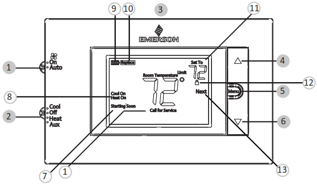 * Whenever
 Replace ” appears in the display, new premium brand AA alkaline batteries should be installed. If the house will be unoccupied for an extended period and either “
 ” or “ Replace ” is displayed, nstall new batteries before leaving.
USER MENU
To customize thermostat settings, press the Menu button from the home screen. Use the Next button to advance through menu items. Press ![]() or
or ![]() to change the setting.
to change the setting.
| User’s Menu # (Press Menu button and release) |
Description | Default Setting (flashing icons) | Settings (Press |
| 01 | Fahrenheit or Celsius | °F | °F — Fahrenheit °C – Celsius |
| 02 | Temperature Display Adjustment (adjust the Room Temperature) | 0 | -5 to +5 |
| 03 |
Continuous Display Light (keep the backlight always on —”C” wire required) | OFF | On — always on OFF—momentarily |
| 04 | Keypad Lock (prevent unwanted changes to the thermostat) | OFF | On — disable buttons OFF—all buttons are active |
• Keypad Lockout – To prevent unwanted changes, the buttons can be disabled. To turn this feature On, press and hold![]() and the Menu button until the icon appears (this can also be turned on in the menu). To turn Off, press and hold
and the Menu button until the icon appears (this can also be turned on in the menu). To turn Off, press and hold ![]() and the Menu button for 3 seconds.
and the Menu button for 3 seconds.
TROUBLESHOOTING
| Symptom | Possible Cause | Corrective Action |
| No Heat/ No Cool/ No Fan (common problem) |
1.)Blown fuse or tripped circuit breaker 2.)Furnace power switch to OFF 3.)Furnace blower compartment door panel loose or not properly installed 4.) Lose connection to thermostat or system |
1)Replace fuse or reset the breaker 2.)Turn the switch to ON 3.)Replace door panel in the proper position to engage safety interlock or door switch 4.)Tighten Connections |
| No Heat | 1.)System Switch not set to Heat 2.) Lose connection to thermostat or system 3.)Heating System requires service or thermostat requires replacement |
Verify thermostat and system wires are securely attached. Diagnostic: Set System Switch to Heat and raise the setpoint above room temperature. Within five minutes the thermostat should make a soft click sound and “Heat On” should appear on display. This sound indicates the thermostat is operating properly. If the thermostat does not click, try the reset operation listed below. If the thermostat does not click after being reset, contact your heating and cooling service person or place of purchase for a replacement. If the thermostat clicks, contact the furnace manufacturer or a service person to verify the heating system is operating correctly. |
| No Cool | 1.)System Switch not set to Cool 2.) Lose connection to thermostat or system 3.)Cooling System requires service or thermostat requires replacement |
Verify thermostat and system wires are securely attached. Diagnostic: Set System Switch to Cool and lower setpoint below room temperature. Same procedures as diagnostic for “No Heat” condition except set the thermostat to Cool and lower the setpoint below the room temperature. There may be up to a five-minute delay before the thermostat clicks in Cooling if the compressor lock-out option is selected in the installer menu. (see INSTALLER MENU, item 50) |
| Heat, Cool, or Fan Runs Constantly | Possible short in wiring, thermostat, heat cool or fan system |
Check each wire connection to verify they are not shorted or touching other wires. Try resetting the thermostat. If the condition persists contact your HVAC service person |
| Thermostat Display &Thermometer Disagree | Thermostat display requires adjustment | The display can be adjusted +/-5°. See User Menu item 04 |
(Troubleshooting continued on next page)
| Symptom | Possible Cause | Corrective Action |
| Furnace (Air Conditioner) CyclesToo Fast or Slow (narrow or wide temperature swing) | The location of the thermostat and/or the size of the Heating System may be influencing the cycle rate | Digital thermostats provide precise control and cycle faster than older mechanical models. The system turns on and off more frequently but runs for a shorter time. If you would like to increase cycle time, choose SLO for the slow cycle in the Installer menu. (Reference menu items 30 & 35) If an acceptable cycle rate is not achieved, contact your HVAC service person. |
| “Call for Service” icon appears on display | 1.)Heating system is not able to heat the space to within 10 degrees of the setpoint within 2 hours 2.)Cooling system is not able to cool the space to within 10 degrees of the setpoint within 2 hours 3.)If “–” is displayed for the Room Temperature, a replacement thermostat is needed 4.)None of the buttons operate on the thermostat |
1.)See corrective action for “No Heat” 2.)See corrective action for “No Cool” 3.)Replace the thermostat 4.)Make sure keypad lockout is not turned on (denoted by A icon) |
Resetting the Thermostat or Thermostat Settings
If the thermostat has good batteries, but has a blank display or does not respond to keypresses, the thermostat should be reset by removing the batteries for 2 minutes. This reset will not change the menu settings. If the condition persists after reinstalling the batteries, replace the thermostat.
To conveniently reset only the user settings back to factory defaults, press the Menu and Backlight buttons at the same time and hold until the display goes blank and resets.
WARNING: This product contains a chemical known to the state of California to cause cancer and birth defects and other reproductive harm.
HOMEOWNER HELPLINE: 1-800-284-2925
Emerson and White-Rodgers are
trademarks of Emerson Electric Co.
©2017 Emerson Electric Co.
All rights reserved.
Operating Instructions
Single Stage Thermostat
Common
White-Rodgers
![]()
With Auto-Time Setting System, 1.4″Blue Jumbo Display, Dual Alarms, FM Radio, USB Charge Out, Night Light and Bluetooth Speaker
CKS1507
Alarm Clock Radio with Bluetooth,USB
Visit our web site at www.emersonradio.com
WARNING
TO PREVENT FIRE OR SHOCK HAZARD , DO NOT USE THIS PLUG WITH AN EXTENSION CORD,RECEPTACLE OR OTHER OUTLET UNLESS THE BLADES CAN BE FULLY INSERTED AND THERE IS NO BLADE EXPOSURE . TO PREVENT FIRE OR SHOCK HAZARD, DO NOT EXPOSE THIS APPLIANCE TO RAIN OR MOISTURE.
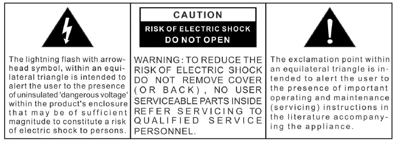
- WARNING: SHOCK HAZARD – DO NOT OPEN
- Caution Marking and rating plate was located at rear enclosure of the apparatus.
- Attention should be drawn to the environmental aspects of battery disposal;
- Minimum distances 10cm around the apparatus for sufficient ventilation;
- The ventilation should not be impeded by covering the ventilation openings with items, such as newspapers , table-cloths, curtains, etc.
- No naked flame sources , such as lighted candles, should be placed on the apparatus;
- The use of apparatus in moderate climates.t
- To reduce the risk of fire or electric shock, do not expose this apparatus to rain or moisture .
Do not ingest the battery, Chemical Burn Hazard
This product contains a coin/button cell battery. If the coin/button cell battery is swallowed, it can cause severe internal burns in just 2 hours and can lead to death . Keep new and used batteries away from children.
If the battery compartment does not close securely, stop using the product and keep it away from children. If you think batteries might have been swallowed or placed inside any part of the body, seek immediate medical attention.
When a plug on the unit is used as a disconnect device. this unit must remain readily accessible.
The batteries (battery pack or batteries installed) shall not be exposed to excessive heat such as sunshine, fire or the like.
ATTENTION Danger of explosion if the battery is not replaced correctly. Replace only with the same type or equivalent type The appliance must not be exposed to water dripping or splashing and that no objects filled with liquids such as vases should be placed on the appliance.
IC Warning
This device complies with Industry Canada License-exempt RSS standard(s).Operation is subject to the following two conditions:(1)this device may not cause interference. and (2)this device must accept any interference, including interference that may cause undesired operation of the device.
RF warning statement
The device has been evaluated to meet general RF exposure requirement. To maintain compliance with RSS-102- Radio Frequency (RF) Exposure guidelines, this equipment should be install led and operated with a minimum distance of 20cm between the radiator and your body.
FCC Note
FCC Part 15.19 Warning Statement
THIS DEVICE COMPLIES WITH PART 15 OF THE FCC RULES.OPERATION IS SUBJECT TO THE FOLLOWING TWO CONDITIONS:(1 )THIS DEVICE MAY NOT CAUSE HARMFUL INTERFERENCE, AND(2)THIS DEVICE MUST ACCEPT ANY INTERFERENCE RECEIVED. INCLUDING INTERFERENCE THAT MAY CAUSE UNDESIRED OPERATION.
FCC Part 15.21 Warning Statement
NOTE: THE GRANTEE IS NOT RESPONSIBLE FOR ANY CHANGES OR MODIFICATIONS NOT EXPRESSLY APPROVED BY THE PARTY RESPONSIBLE FOR COMPLIANCE.SUCH MODIFICATIONS COULD VOID THE USER AUTHORITY TO OPERATE THE EQUIPMENT.
FCC Part 15.105 Warning Statement
Note: This equipment has been tested and found to comply with the limits for a class B digital device ,pursuant to part 15 of the FCC Rules. These limits are designed to provide reasonable protection against harmful interference in a residential installation .This equirement generates, uses and can radiate radio frequency energy and, if not installed and used in accordance with the instructions, may cause harmful interference to radio communications. However there is no guarantee that interference will not occur in a particular installation. If this equipment does cause harmful interference to radio communications. However there is no guarantee that interference to radio communication .If this equirement does cause harmful interference to radio or television reception, which can be determined by turning the equirement off and on ,the user is encouraged to try to correct the interference by one or more of the following measures:
- Reorient or relocate the receiving antenna .
- Increase the separation between the requirement and receiver.
- connect the requirement into an outlet on a circuit different from that to which the receiver is connected.
- consult the dealer or an experienced radio/TV technician for help.
RF warning statement
The device has been evaluated to meet general RF exposure requirement.
To maintain compliance with FCC”s RF exposure guidelines, this equipment should be installed and operated with a minimum distance of 20cm between the radiator and your body.
Important Safety Instructions
- Read these instructions. Keep these instructions. Follow all instructions. Heed all warnings.
- Do not use this apparatus near water.
- Clean only with a dry cloth.
- Do not block any ventilation openings. Install in accordance with the manufacturer’s instructions.
- Do not install near any heat sources such as radiators, heaters, stoves, or other apparatus(including amplifiers) that produce heat.
- Do not defeat the safety purpose of the polarized or grounding-type plug. A polarized plug has two blades with one wider than the other. A grounding-type plug has two blades and a third grounding prong. The wide blade or the third prong is provided for your safety. If the provided plug does not fit into your outlet, ask an electrician to replace the obsolete outlet.
- Protect the power cord from being walked on or pinched particularly at plugs, convenience receptacles and the point where they exit from the apparatus.
- Only use attachments/ accessories specified by the manufacturer.
- Unplug this apparatus during lightning storms or when unused for long periods of time.
- Refer all servicing to qualified service personnel. Servicing is required when the apparatus has been damaged in any way, such as power-supply cord or plug is damaged, liquid has been spilled or objects have fallen into the apparatus. the apparatus has been exposed to rain or moisture. does not operate normally, or has been dropped.
- Use only with the cart, stand, tripod, bracket, or table specified by the manufacturer. or sold with the apparatus. When a cart is used, use caution when moving the cart/ apparatus combination to avoid injure from tip-over.
- The AC adapter must not be exposed to dripping or splashing and no objects filled with liquids, such as vases, shall be placed on apparatus.
- The AC adapter is used as a disconnect device and it must remain readily accessible during intended use. In order to disconnect the apparatus from the AC power completely, the AC adapter must be removed from the AC outlet completely.
- The battery must not be exposed to excessive heat such as sunshine, fire, etc.
CAUTION: Danger of explosion if the battery is incorrectly replaced. Replace only with the same or equivalent type.
Preparation For Use
Unpacking And Set Up
- Remove the radio from the carton and remove all packing material from the radio. Save the packing material. If possible, in case the radio ever needs to be serviced or transported. The original carton and packing material is the only safe way to pack your radio to protect it from damage in transit.
- Remove any descriptive labels or stickers on the front or top of the cabinet. Do not remove any labels or stickers from the back or bottom of the cabinet.
- Note the serial number on the bottom of your radio and write this number in the space provided on the Warranty page of this manual.
- Place your radio on a level surface such as a table, desk or shelf, convenient to an AC outlet, out of direct sunlight, and away from sources of excess heat, dirt, dust, moisture, humidity, or vibration.
- Unwind the Line cord connecting the AC adapter and extend it to its full length . The FM antenna is built in to this cord. It must be fully extended to provide the best FM reception.
Protect Your Furniture
This model is equipped with non-skid rubber ‘feet’ to prevent the product from moving when you operate the controls. These ‘feet’ are made from non-migrating rubber material specially formulated to avoid leaving any marks or stains on your furniture. However certain types of oil based furniture polishes , wood preservatives, or cleaning sprays may cause the rubber ‘feet’ to soften. and leave marks or a rubber residue on the furniture. To prevent any damage to your furniture we strongly recommend that you purchase small self-adhesive felt pads, available at hardware stores and home improvement centers everywhere, and apply these pads to the bottom of the rubber ‘feet’ before you place the product on fine wooden furniture.
Power Source
This radio is designed to operate on normal 120V 60Hz AC power only. Do not attempt to operate the radio on any other power source . You could cause damage to the radio that is not covered by your warranty. This radio should be connected to an AC outlet that is always ‘live’. Do not connect it to an outlet that is controlled by a wall switch. When the power to the radio is interrupted, the built-in lithium battery takes over to maintain the time and alarm settings. To maximize the life of the lithium battery keep the radio connected to a ‘live’ AC outlet at all times.
Important Notes
- Avoid installing this unit in places exposed to direct sunlight or close to heat-radiating appliances such as: electric heaters, on top of other stereo equipment that radiates heat, places lacking ventilation, dusty areas, places subject to constant vibration and/or humid or moist areas.
- Operate controls and switches as described in the manual.
- Before turning on the power, make certain that the AC adapter is properly installed.
- When moving the set, be sure to first disconnect the AC adapter.
Package Contents
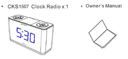
Location of Controls and Indicators
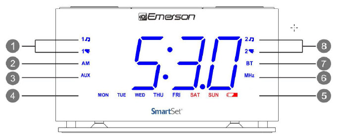
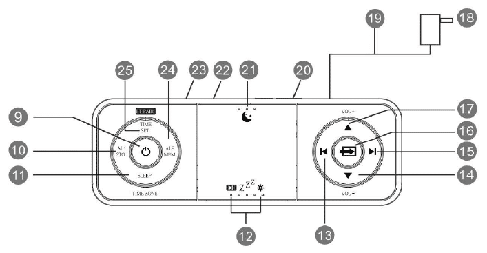
- ALARM 1 Radio/Buzzer Indicators
- AM Indicator ( ‘On’=AM, ‘Off’=PM)
- AUX Indicator
- DAY of WEEK Indicators
- LOW BATTERY Indicator
- MHZ (FM Radio) Indicator
- BT (Bluetooth) Indicator
- ALARM 2 Radio/Buzzer Indicators (located on back of unit)
- POWER ( ‘On’/Standby) Button
- ALARM 1/STORE(FM station ) Button
- SLEEP/TIME ZONE Button
- PAUSE/SNOOZE/DIMMER Button
- SET/TUNE DOWN Buttons
- VOLUME- DOWN Button
- SET/TUNE UP Button
- SOURCE (FM, Bluetooth, AUX) Button
- VOLUME+ UP Button
- AC Adapter
- FM Antenna(cable)
- BACKUP BATTERY Compartment
- Night Light On/Off Button
- USB Charge Out
- AUX IN Jack
- ALARM 2/MEMORY(FM station)
- TIME SET/FM Frequency Display
Setting the Time Zone
Initial Default Setting at Clock Mode
The first time you connect your new SmartSet® clock radio to the AC outlet the internal computer will automatically set the time correctly for the Eastern Time Zone, which is the initial default setting. The display will scan for a few seconds and then show the correct Day and Time in the Eastern zone. If you live in the Eastern Time zone, there’s nothing else to do.
Your clock is set correctly and running.
If you don’t not live in the Eastern Time zone you must change the default zone display to your own zone. You only do this one time and the SmartSet®will remember the new default zone setting and will always return to that setting after power interruption.
There are 7 time zones programmed into your SmartSet®clock radio as follows:
- ZONE 1 -Atlantic Time
- ZONE 2 -Eastern Time (Default Setting)
- ZONE 3 -Central Time
- ZONE 4 -Mountain Time
- ZONE 5 -Pacific Time
- ZONE 6 -Yukon Time
- ZONE 7 -Hawaiian Time
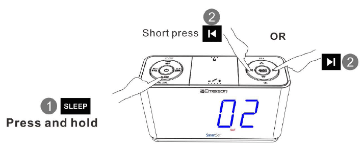
Setting the Time
Year, Date and Time Display
To display Year. Date and Time sequentially, short press TIME SET once for each
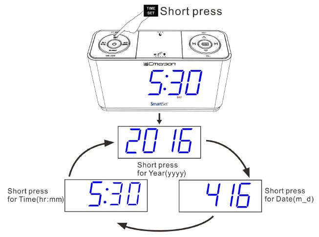
Manual Time Adjustments
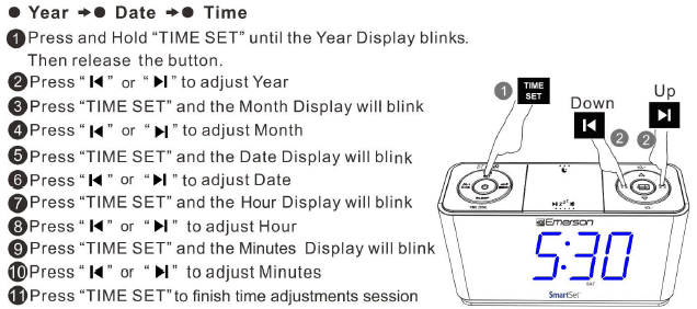
Note: To skip manual adjustments, keep it idle for 5 seconds to resume to clock display mode.
Daylight Saving and Leap Year Adjustments
All Daylight Saving and Leap Year adjustment are made automatically by the SmartSet internal computer as follow:
Start of Daylight Saving time:
At 2:00 AM on the 2nd Sunday in March, the clock will automatically advance to 3:00 AM
End of Daylight Saving time:
At 3:00 AM on the 1st Sunday in November, the clock will automatically reset to 2:00 AM
Leap Year:
At 12:00 Midnight on February 28th , the calendar display will change to”2 29″ .
Setting the Alarm
The alarm can only be set in standby mode where the function of Radio , Bluetooth, and AUX are disabled (i.e. indicators of “MHz “,” BT” ,and “AUX” are OFF)
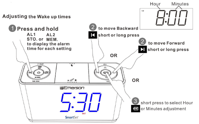
Adjusting Alarm Week Mode
Press and Hold “AL 1″ or”AL2”,then press “DOWN” or “UP” to adjust: Weekdays (Monday to Friday), Weekends (Saturday and Sunday) or Everydays (Monday to Sunday)


Wake To Radio and Alarm Volume Setting
- Press POWER button to turn the unit ON.
- Press SOURCE button to select FM Radio mode.
- Tune to or recall from Memory the station that you wish to hear when the alarm comes ON.
- Press Vol+ or Vol- to set the maximum radio volume at which the alarm will reach gradually at wake up time.
- Default alarm volume is U08 for radio volume set up between UOO-U08(before the unit turned OFF to standby mode). For a louder alarm , set up radio volume above U08 before the unit turned OFF.
Snooze Alarm
When the Alarm comes ON, press SNOOZE button z22, to pause it for 9 minutes .Snooze Alarm will not repeat after one hour. To turn off Snooze Alarm mode ,press the POWER button once.
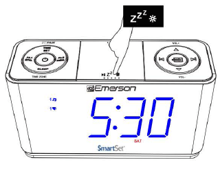
Listening to FM Radio
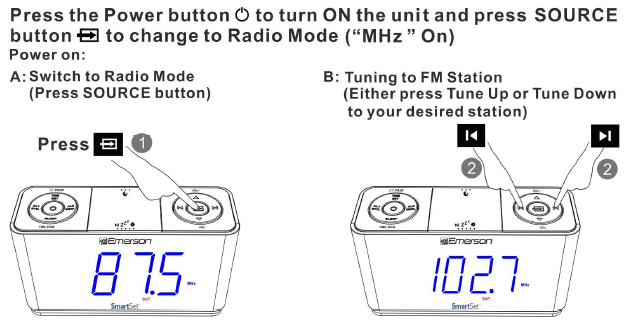
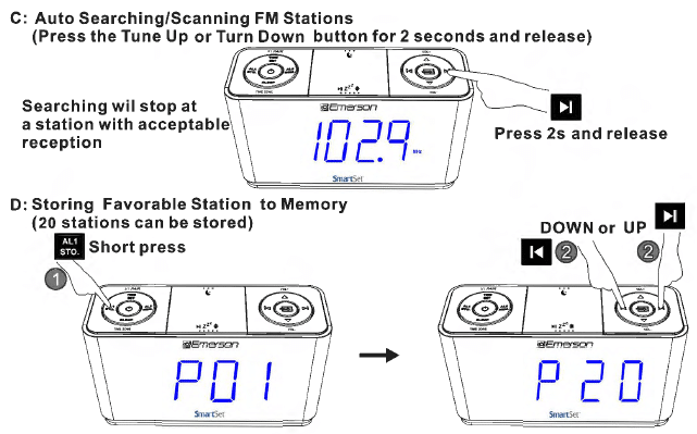
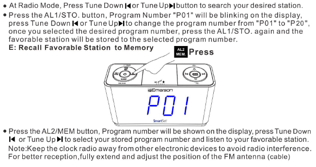
Recall Favorable Station
- Press the POWER button to turn the unit ON
- Press the SOURCE button to select Bluetooth (bt) mode ( “BT” flashes for pairing)
- Enable your Bluetooth device and select CKS1507 from its Available/Paired device list. After paring successfully, the unit will prompt and “BT” will become solid
- Automatic connection with your Bluetooth devices is possible if they have been paired successfully with this unit before.
- After paired. you can play your music through this Bass Boosted Bluetooth Speaker.
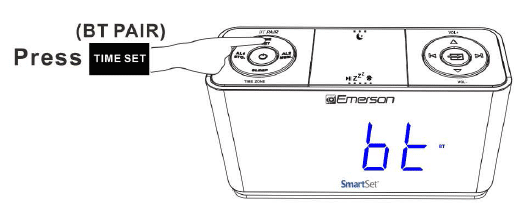
Sleeping to Music Timer
Press the Power button (‘.) to turn ON the unit, and press SOURCE button to select either FM Radio, Bluetooth or AUX mode to play radio or music
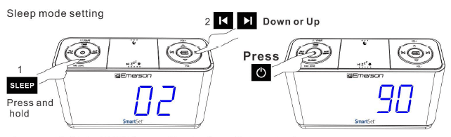
- Press and hold the SLEEP button. The display will show the sleep timer.
- Press Up or Down button to choose your desired sleep timer (02-90 minutes). , Release all buttons, the sleep timer will start counting down and turn off the unit when the desired sleep timer elapsed.
- To display the sleep timer during the countdown process, press the SLEEP button.
- To cancel the sleep timer during the countdown process, press the POWER button to shut off the unit.
Level Dimmer Control
The brightness of the clock display can be set at High/Medium/Low level in standby, Radio and AUX modes with a press of the ZZZ button
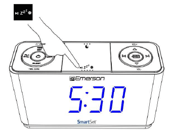
Night Lighting
Press the NIGHT LIGHT button to turn the blue nightlight ON or OFF when needed
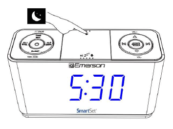
Enjoying Audio Source via AUX IN Jack
Press the POWER button to turn the unit ON
Press SOURCE button until “AUX” appears on LED display, connect your audio or mobile device and play music through the unit with the 3.5mm earphone jack.
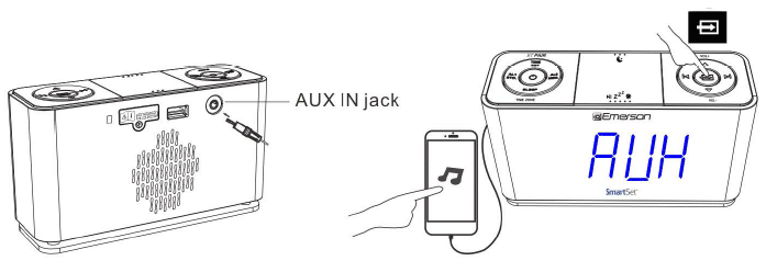
USB for Charging
Output 5V up to 1.5A for charging mobile phone or portable digital audio player.
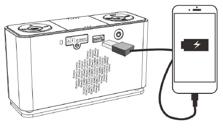
Note: Charging current drawn from the unit may vary due to different USB charging cable condition or battery charging characteristics
Changing the Lithium Battery
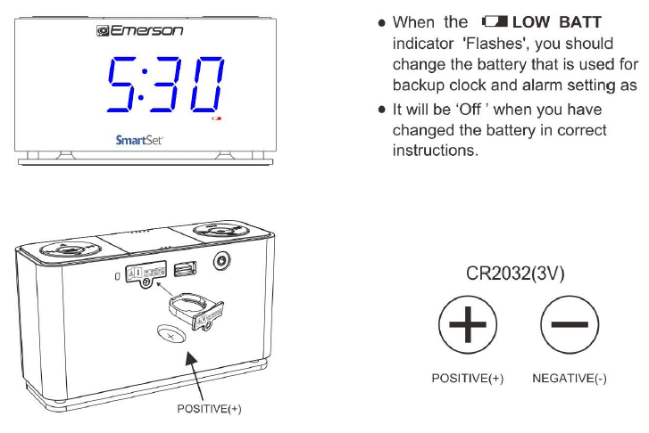
The battery backup is intended for short power outages only. The unit’s primary functions cannot run on the battery backup alone. This unit uses a button cell battery that will last up to 1 year and maintains the time.
WARNING
DANGER OF EXPLOSION IF BATTERY IS INCORRECTLY REPLACED. REPLACE ONLY WITH THE SAME OR EQUIVALENT TYPE. DO NOT INGEST BATTERY,CHEMICAL BURN HAZARD
This product contains a coin/button cell battery. If the coin/button cell battery is swallowed it can cause severe internal bums in just 2 hours and can lead to death. Keep new and used batteries away from children .If the battery compartment does not close securely stop using the product and keep it away from children. If you think batteries might have been swallowed or placed inside any part of the body seek immediate medical attention.
The apparatus must not be exposed to dripping or splashing and objects filled with liquids, such as vases, must not be placed on the apparatus.

This marking indicates that this product should not be disposed of with other household wastes throughout the country .To prevent possible harm to the environment or human health from uncontrolled waste disposal, recycle this unit responsibly so as to promote the re-use of material resources. To return your used device, please use return and collection systems or contact the retailer where the product was purchased as they know how to safely recycle this product.
Care and Maintenance
Care Of Cabinet
If the cabinet becomes dusty. wipe it with a soft cloth. If the cabinet becomes smudged or dirty, clean it with a soft, slightly dampened cloth. Never allow water or any liquid to get inside the cabinet. Never use any abrasive cleaners or cleaning pads as these will damage the finish of your radio .
Lithium Battery Precautions
- Dispose of the old battery properly. Do not leave it lying around where a young child or pet could play with or swallow it. If the battery is swallowed, contact a physician immediately.
- The battery may explode if mistreated. Do not attempt to recharge it or disassemble it. Do not dispose of the old battery in a fire.
LIMITED WARRANTY
Emerson Radio Corp. warrants this product to be free from manufacturing defects in original material, including original parts, and workmanship under normal home use and conditions (“manufacturing defect”) for a period of ninety (90) days from date of the original purchase in, and if used in the United States. Should service be necessary under this warranty, Emerson will provide the following at our Return Repair Facility provided the manufacturing defect is verified along with the date of
purchase:
- Repair service for ninety (90) days from date of original purchase at no charge for labor and parts.
To Receive Authorization to Return a Defective Item , please contact Emerson Customer Service at 1-800-898-9020. Have your Model number, Serial Number and dated Proof of Purchase with you when you call .
In the event the product must be returned to Emerson:
- Pack the unit in a well-padded heavy corrugated box. Please insure the item is well padded to avoid damage while in transit back to our facility. If the item incurs damage, it will NOT be replaced and the consumer will be responsible for return freight costs to receive their same unit back.
- Enclose your check or money order payable to Emerson Radio in the amount of $10 to cover return shipping and handling costs.
- Enclose a note with your name, address, phone number, Return Authorization number and brief reason for returning the unit.
- Enclose a copy of your proof of purchase (warranty service will not be provided without dated proof of purchase).
- Ship the unit prepaid via UPS or parcel post (SHIP INSURED and obtain a
tracking number).
NOTE: This warranty does not cover:
- Damage to equipment not properly connected to the product.
- Cost incurred in the shipping of the product to and from Emerson’s Return Facility.
- Damage or improper operation of unit caused by customer abuse, misuse, negligence or failure to follow operating instructions (including cleaning instructions) provided with the product.
- Ordinary adjustments to the product which can be performed by customer as outlined in the owner’s manual.
- Signal reception problems caused by external antenna or cable systems.
- Products not purchased in the United States.
- Damage to product if used outside the United States.
THIS WARRANTY IS NON-TRANSFERABLE AND APPLIES ONLY TO THE ORIGINAL PURCHASER AND DOES NOT EXTEND TO SUBSEQUENT OWNERS OF THE PRODUCT. ANY APPLICABLE IMPLIED WARRANTIES, INCLUDING THE WARRANTY OF MERCHANTABILITY, ARE LIMITED IN DURATION TO A PERIOD OF THE EXPRESSED WARRANTY AS PROVIDED HEREIN BEGINNING WITH THE DATE OF ORIGINAL PURCHASE AT RETAIL AND NO WARRANTIES, WHETHER EXPRESSED OR IMPLIED, SHALLAPPLYTOTHE PRODUCT THEREAFTER. EMERSON MAKES NO WARRANTY AS TO THE FITNESS OF THE PRODUCT FOR ANY PARTICULAR PURPOSE OR USE.THE EXTENT OF EMERSON RADIO CORP’S LIABILITY UNDER THIS LIMITED WARRANTY IS THE REPAIR OR REPLACEMENT PROVIDED ABOVE AND, IN NO EVENT, SHALL EMERSON RADIO CORP’S LIABILITY EXCEED THE PURCHASE PRICE PAID BY THE PURCHASER OF THE PRODUCT. UNDER NO CIRCUMSTANCES SHALL EMERSON RADIO CORP. BE LIABLE FOR ANY LOSS, DIRECT, INDIRECT, INCIDENTAL, SPECIAL, OR CONSEQUENTIAL DAMAGE ARISING OUT OF OR IN CONNECTION WITH THE USE OF THIS PRODUCT. THIS WARRANTY IS VALID ONLY IN THE UNITED STATES OF AMERICA.THIS WARRANTY GIVES YOU SPECIFIC LEGAL RIGHTS. HOWEVER, YOU MAY HAVE OTHER RIGHTS WHICH MAY VARY FROM STATE TO STATE. SOME STATES DO NOT ALLOW LIMITATIONS ON IMPLIED WARRANTIES OR EXCLUSION OF CONSEQUENTIAL DAMAGE, THEREFORE THESE ESTRICTIONS MAY NOT APPLY TO YOU.
The serial number can be found on the back cabinet We suggest that you record the serial number of your unit in the space below for future reference
Model Number: CKS1507
Serial Number: 10-90-1402A
FAQS
Is this electric or strickly battery operated?
Electric but has a battery backup
How do you change time zones?
According to the instruction manual that came with mine, 1) press and hold the ‘sleep’, 2) short press the ‘reverse’ or the ‘forward’. Zone 1 is Atlantic Time, 2 is Eastern Time (which is the default setting), 3 is Central, 4 is Mountain, 5 is Pacific, 6 is Yukon and 7 is Hawaiian.
does this alarm clock have to be plugged in?
As stated several times, the radio is electric with a battery backup, so yes, it has to be plugged in.
Does this have built in speakers?
Yes, it has a built in speaker.
How long can the product be used?
Years
What is al1 sto. and al2mem difference?
AL1 sto. button allows you to store your favorite radio station. You have 20 stations saved as designated by P01 through P20. AL2 mem button recalls the station that was stored.
Will this alarm clock Bluetooth to headphones?
No
how do you set the alarm for one time?
For this product: Emerson CKS1507, you need to do the following; Press and hold AL1 or AL2 and the UP or DOWN arrow on the opposite side of the clock to select the weekdays and weekends for alarm. The left and right buttons allow you to select value of (hours / minutes). To select hours or minutes while you are adjusting AL1 or AL2 you need to push the center button where the Arrows are. Remember, you need to press and hold the AL1 or AL2 button while selecting the time and day for the alarm.
can led display be turned off all the way?
No
How do you change the radio stations?
Turn on the Radio by pushing the Power Button then Press the Tune Up or Tune Down Button to your desired radio station.
How long can the product be used?
Indefinitely.
Is it a plug in?
Yes. If you can’t find it on Amazon for less than $20 try Walmart. Also a great radio and night light.
What is the difference between CKS1507 and CKS1508?
The difference is that CKS1508 has a clock display on the top of the unit, while CKS1507 does not.
How do I set the time on my alarm clock?
Press and hold SET until you hear a beep (about 5 seconds). Then use the UP/DOWN buttons to set the hour and press SET to confirm. Use the UP/DOWN buttons to set the minutes and press SET to confirm.
How do I set my alarm?
Use the UP/DOWN buttons to select AM or PM. Press SET to select AM or PM. Use UP/DOWN buttons to select hour and press SET to confirm. Use UP/DOWN buttons to select minutes and press SET to confirm. You will hear two short beeps when your alarm is set.
How do I turn off my alarm?
Press SNOOZE once, your alarm will turn off temporarily for 9 minutes. Press SNOOZE again, your alarm will turn off temporarily for 5 minutes. Press SNOOZE again, your alarm will turn off temporarily for 1 minute. If you want to stop snoozing, just press SNOOZE once more and your alarm will sound again in 9 minutes.
Is this radio Bluetooth compatible to pair in my Android smartphone?
Actually it is, just looked in the manual.
how do you delete alarms?
Short press AL1 or AL2 until the buzzer or radio light is off.
Patent Information : U.S. Patent 6,657,344
]]>