EMERSON Micro Motion 5700 Transmitter for Coriolis Flow Meters
![]()
Coriolis Flow Meter with Micro Motion™ 570 Transmitters
Safety
Safety Manual for Safety Instrumented Systems (SIS)
Safety messages
Safety messages are provided throughout this manual to protect personnel and equipment. Read each safety message carefully before proceeding to the next step.
Safety and approval information
This Micro Motion product complies with all applicable European directives when properly installed in accordance with the instructions in this manual. Refer to the EU declaration of conformity for directives that apply to this product. The following are available: the EU Declaration of Conformity, with all applicable European directives, and the complete ATEX installation drawings and instructions. In addition, the IECEx installation instructions for installations outside of the European Union and the CSA installation instructions for installations in North America are available at Emerson.com or through your local Micro Motion support center.
Information affixed to equipment that complies with the Pressure Equipment Directive, can be found at Emerson.com. For hazardous installations in Europe, refer to standard EN 60079-14 if national standards do not apply.
Other information
Troubleshooting information can be found in the Configuration Manual. Product data sheets and manuals are available from the Micro Motion web site at Emerson.com.
Return policy
Follow Micro Motion procedures when returning equipment. These procedures ensure legal compliance with government transportation agencies and help provide a safe working environment for Micro Motion employees. Micro Motion will not accept your returned equipment if you fail to follow Micro Motion procedures.
Return procedures and forms are available on our web support site at Emerson.com, or by calling the Micro Motion Customer Service department.
Before you begin
About this document
This document provides information about how to install, commission, and proof test a Coriolis flow meter with a 5700 transmitter to comply with Safety Instrumented Systems (SIS) requirements.
Important
This manual assumes that:
- The transmitter has been installed correctly and completely according to the instructions in the transmitter installation manual.
- Users understand basic transmitter and sensor installation, configuration, and maintenance concepts and procedures.
Hazard messages
This document uses the following criteria for hazard messages based on ANSI standards Z535.6-2011 (R2017).
DANGER
Serious injury or death will occur if a hazardous situation is not avoided.
WARNING
Serious injury or death could occur if a hazardous situation is not avoided.
CAUTION
Minor or moderate injury will or could occur if a hazardous situation is not avoided.
NOTICE
Data loss, property damage, hardware damage, or software damage can occur if a situation is not avoided. There is no credible risk of physical injury.
Physical access
WARNING
Unauthorized personnel can potentially cause significant damage and/or misconfiguration of end users’ equipment. Protect against all intentional or unintentional unauthorized use.
Physical security is an important part of any security program and fundamental to protecting your system. Restrict physical access to protect users’ assets. This is true for all systems used within the facility.
Related documents
You can find all product documentation on the product documentation DVD shipped with the product or at Emerson.com. For more information, see any of the following documents:
- Micro Motion 5700 Product Data Sheet
- Micro Motion 5700 Transmitters with Configurable Inputs and Outputs: Configuration and Use Manual
- Micro Motion 5700 Transmitters with Intrinsically Safe Outputs: Configuration and Use Manual
- Micro Motion 5700 Transmitters with Configurable Inputs and Outputs: Installation Manual
- Micro Motion 5700 Transmitters with Intrinsically Safe Outputs: Installation Manual
- Emerson sensor installation manual
- Emerson sensor product data sheets
- Report No. MiMo 18-01-016 R001 V2R2 FMEDA 5700, prepared for Emerson by exida.com LLC
Installation and commissioning
Note
Smart Meter Verification is the only add on option that is compatible with the SIL license.
Use this section to install and commission a Coriolis flow meter with a 5700 transmitter with SIS features.
IEC 61508 relevant requirements
The Coriolis flow meter with a 5700 transmitter is certified per the relevant requirements of IEC 61508.
| Systematic capability | Safety Integrity Level (SIL) 3 capable |
| Random capability | • Type B element
• SIL 2 capable @ HFT=0 (single meter) • SIL 3 capable @ HFT=1 (multiple meters) |
Failure rates according to IEC 61508 in FIT (1)
Table 2-1: Failure rates for a 5700 with configurable outputs
| 5700 CIO | λSD | λSU | λDD | λDU |
| 5700I Integral mount transmitter and 5700C 9-wire remote mount transmitter with an integrated core processor | 0 | 72 | 2941 | 107 |
| 5700R 4-wire remote mount transmitter connected to a sensor with a standard core processor | 0 | 71 | 2522 | 78 |
| 5700R 4-wire remote mount transmitter connected to a sensor with an enhanced core processor | 0 | 132 | 3124 | 138 |
Table 2-2: Failure rates for a 5700 with intrinsically safe outputs
| 5700 IS | λSD | λSU | λDD | λDU |
| 5700I Integral mount transmitter and 5700C 9-wire remote mount transmitter with an integrated core processor | 0 | 78 | 3030 | 114 |
| 5700R 4-wire remote mount transmitter connected to a sensor with a standard core processor | 0 | 77 | 2615 | 84 |
| 5700R 4-wire remote mount transmitter connected to a sensor with an enhanced core processor | 0 | 138 | 3214 | 145 |
SIS-certified versions
Emerson maintains an SIS-compliant modification process. Changes made after initial release do not affect overall SIS certification.
Version information is available from the display at About → Versions.
Table 2-3: SIS-certified versions for a 5700 with configurable outputs
| Device | Display tag | Version |
| 5700 firmware | Transmitter | 1.20 and later |
| Integrated Core Processor firmware | Core processor | 4.14 and later |
| Enhanced Core Processor firmware | Core processor | 4.14 and later |
| Standard Core Processor firmware | Core processor | 3.42 and later |
| 5700 hardware | Transmitter hardware | 0 and later |
Table 2-4: SIS-certified versions for a 5700 with intrinsically safe outputs
| Device | Display tag | Version |
| 5700 firmware | Transmitter | 1.0 and later |
| Integrated Core Processor firmware | Core processor | 4.60 and later |
| Enhanced Core Processor firmware | Core processor | 4.60 and later |
| Standard Core Processor firmware | Core processor | 3.42 and later |
| 5700 hardware | Transmitter hardware | 0 and later |
- • On SIS applications for a 5700 with configurable outputs, the Channel A mA output, wired in series with the Channel D mA input in loopback mode, is used for the safety critical variable (mass flow, volume flow, or density). The SIS features are enabled via licensing. While other output channels may be licensed, they are outside the scope of SIS usage.
• On SIS applications for a 5700 with intrinsically safe outputs, the Channel A mA Output is used for the safety critical variable (mass flow, volume flow, or density). The SIS features are enabled through licensing. While other output channels can be licensed, they are outside the scope of SIS usage.
Safety precautions
Prior to making any changes to the 5700 Coriolis flow meter, such as changing the configuration, upgrading the firmware, replacing the transmitter hardware or sensor:
- Take appropriate action to avoid a false trip by electronically bypassing the safety Programmable Logic Controller (PLC).
Important
Ensure alternate means are in place to maintain the process in a safe state.
- Prior to placing the meter online and removing the bypass from the safety PLC, verify the transmitter configuration and all safety parameters.
Set up the 5700
Use this section to make sure the 5700 is installed and configured for SIS applications.
You can use ProLink III, the 5700 display, or a field communicator to verify, or if needed, configure these settings. For more information, see the Micro Motion 5700 Transmitters with Configurable Inputs and Outputs: Configuration and Use Manual or the Micro Motion 5700 Transmitters with Intrinsically Safe Outputs: Configuration and Use Manual.
The sensor does not require special installation in addition to the standard installation procedures in the sensor installation manual.
Set up a 5700 with configurable outputs
Procedure
- Use the Micro Motion 5700 Transmitters with Configurable Inputs and Outputs: Installation Manual to install the 5700, except for the wiring instructions for Channels A and D. Instead, wire Channels A and D using one of the following power options:
- Channel A active (internal) power and Channel D passive (external) power
- Channel A passive (external) power and Channel D passive (external) power
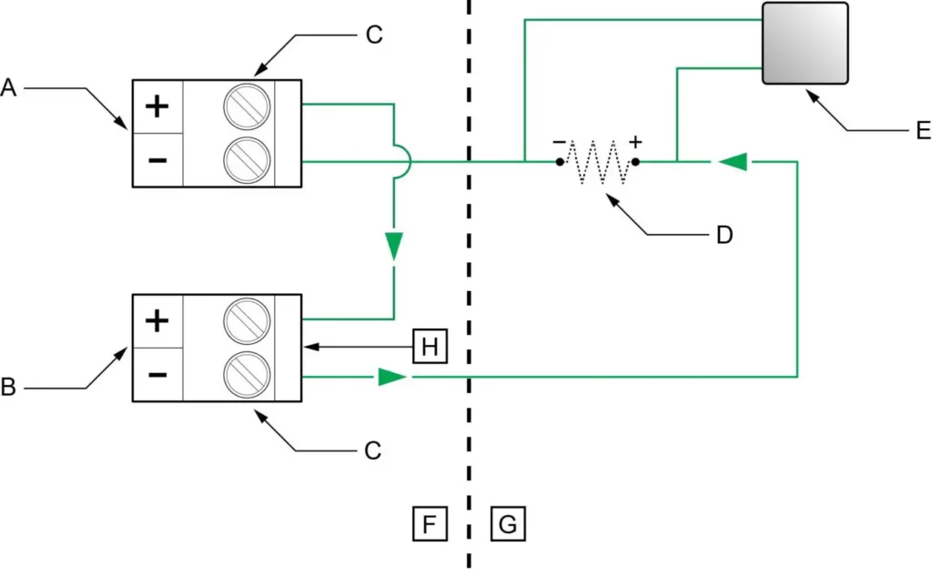
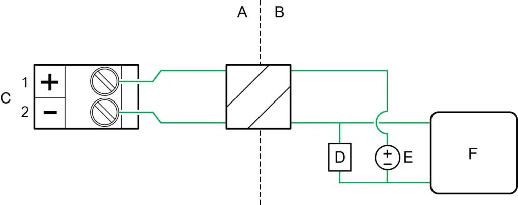
Figure 2-1: Channel A active (internal) and Channel D passive (external) power
- A. Channel A mA output
- B. Channel D mA input
- C. Terminals
- D. 820 ohm maximum loop resistance including 100 ohms (H) for mA input (250–600 ohm for HART communications)
- E. Signal device
- F. Terminal compartment
- G. External to the 5700
- H. 100 ohm input resistance
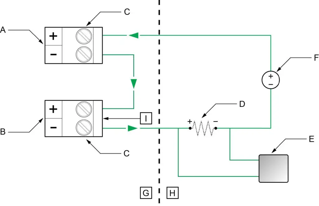
- Figure 2-2: Channel A passive (external) and Channel D passive (external) power
- A. Channel A mA output
- B. Channel D mA input
- C. Terminals
- D. Maximum loop resistance including 100 ohms (I) for mA input — see Figure 2-3.
- E. Signal device
- F. 5–30 VDC (maximum)
- G. Terminal compartment
- H. External to the 5700
- I. 100 ohm input resistance
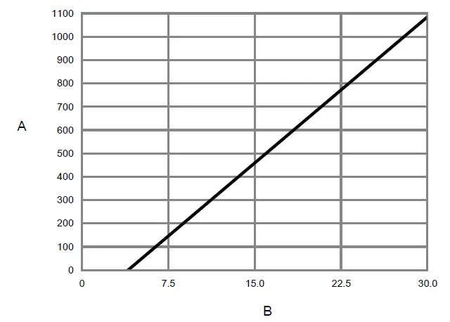
- Figure 2-3: Externally-powered mA/HART output: maximum loop resistance
- A. Maximum resistance (Ω)
- B. External supply voltage (V)
Note
The calculation for loop resistance must include 100 ohms for the mA Input.
- Verify that the following features are licensed: SIL, ChA, ChD.
Note
If SIL is not licensed, see Install the SIL license key. - Verify that Channel D is configured as follows:
Channel D setting Option Channel Type mA Input Power Source External (Passive) mA Input Assignment Loop Current - Verify all safety parameters:
- a) Verify that all appropriate flow and density calibration parameters are set (FCF, K1, K2, D1, D2, and DT).
- b) Verify that the Lower Range Value (LRV) and the Upper Range Value (URV) for Channel A mA Output 1 is configured.
- c) Verify that the appropriate measurement units are configured (mass flow, volume flow, density, and temperature).
- d) Verify that the HART Primary Variable (PV) is assigned to Channel A mA Output.
- e) Verify that the appropriate low flow cutoff parameter is configured.
- f) Verify that the appropriate damping values are configured – such as flow, density, temperature, and added damping.
- g) Verify that the mA Output Fault Action is set to Upscale or Downscale.
Set up a 5700 with intrinsically safe outputs
Procedure
- Use the Micro Motion 5700 Transmitters with Intrinsically Safe Outputs: Installation Manual to mount the transmitter and install the sensor wiring.
- Wire the Channel A passive (external) power to the appropriate output terminal and pins.
- Figure 2-4: Channel A mA/HART output wiring
- A. Hazardous area
- B. Non-hazardous area
- C. mA/HART output
- D. 250–600 Ω resistance
- E. 24V nominal
- F. HART device
- Figure 2-5: Channel A mA/HART supply voltage and loop resistance
- A. Total loop resistance Rmax (including barrier)
- B. Supply voltage VDC (volts)
- C. Operating region with HART
- D. Operating region without HART (includes the C range)
- Figure 2-4: Channel A mA/HART output wiring
- Verify that the following features are licensed: SIL and ChA.
Note
If SIL is not licensed, see Install the SIL license key. - Verify all safety parameters:
- a) Verify that all appropriate flow and density calibration parameters are set (FCF, K1, K2, D1, D2, and DT).
- b) Verify that the Lower Range Value (LRV) and the Upper Range Value (URV) for Channel A mA output 1 is configured.
- c) Verify that the appropriate measurement units are configured (mass flow, volume flow, density, and temperature).
- d) Verify that the HART Primary Variable (PV) is assigned to Channel A mA Output.
- e) Verify that the appropriate low flow cutoff parameter is configured.
- f) Verify that the appropriate damping values are configured – such as flow, density, temperature, and added damping.
- g) Verify that the mA Output Fault Action is set to Upscale or Downscale.
Diagnostics
Diagnostics for a 5700 with configurable outputs
The SIL license enables a mA Output to mA Input comparison diagnostic.
If the difference between the programmed mA Output and the actual mA Input exceeds
0.2 mA, an Electronics Failed alert becomes active and all analog outputs will be turned off (outputs all to zero) within 5 minutes. The alert shows up as:
| On the display as: | Verification of mAO1 Failed |
| On ProLink III as: | mAO Verification Failed |
After 5 minutes, the outputs are turned back on, and the mA Output to mA Input comparison check is performed again. If the alert was due to a transient condition, since cleared, the transmitter will resume normal operations. If the alert was due to a component failure, the alert will remain active and the outputs will turn off again.
Note
The mA Output to mA Input comparison diagnostic is disabled for the first 5 minutes after the transmitter is powered up. This allows time to verify correct wiring and operation of the ChA-ChD mA Output with mA Input loopback.
Diagnostics for a 5700 with intrinsically safe outputs
The SIL license enables a mA Output to internal mA Readback comparison diagnostic.
If the difference between the programmed mA Output and the actual internal mA Readback exceeds 0.2 mA, an Electronics Failed alert becomes active and all analog outputs will be turned off (outputs all to fault state) within 5 minutes. The alert shows up as:
| On the display as: | Verification of mAO1 Failed |
| On ProLink III as: | mAO Verification Failed |
After 5 minutes, the outputs are turned back on, and the mA Output to internal mA Readback comparison check is performed again. If the alert was due to a transient condition, since cleared, the transmitter will resume normal operations. If the alert was due to a component failure, the alert will remain active and the outputs will turn off again.
Note
The mA Output to mA Readback comparison diagnostic is disabled for the first 5 minutes after the transmitter is powered up. This allows time to verify correct wiring and operation of the ChA mA Output with internal mA Readback.
Enable or disable software write-protection
| Display | Use the mechanical switch on the display. |
| ProLink III | Device Tools → Configuration → Write-Protection |
When enabled, Write-Protection prevents changes to the transmitter configuration. You can perform all other functions, and you can view the transmitter configuration parameters.
Note
The write protection setting via software methods (such as ProLink III) is available only on transmitters without a display.
For transmitters with a display, write protection is available only using the lock switch on the display.![]()
Write-protecting the transmitter primarily prevents accidental changes to configuration, not intentional changes. Any user who can make changes to the configuration can disable write protection.
Upgrade the transmitter firmware
You can upgrade the transmitter firmware to stay current with development and to take advantage of any new features.
Using a USB drive with the display
You can upgrade the transmitter firmware to stay current with development and to take advantage of any new features.
Prerequisites
You must have the firmware upgrade files provided by Micro Motion.
The service port must be enabled. It is enabled by default. However, if you need to enable it, choose Menu → Configuration → Security and set Service Port to On.
Procedure
- Copy the folder containing the firmware upgrade files to a USB drive.
- Open the wiring compartment and insert the USB drive into the service port.
WARNING
If the transmitter is in a hazardous area, do not remove the housing cover while the transmitter is powered up. Failure to follow these instructions can cause an explosion resulting in injury or death. - Follow the prompts once the transmitter recognizes the USB drive.
- Select USB Drive –> Transmitter.
- Select Update Device Software.
- Select the firmware upgrade folder and follow the prompts.
Note
If required, the transmitter upgrade procedure automatically includes an upgrade to the core processor software.
If you chose to reboot the transmitter at a later date, you can reboot it from the menu, or you can power-cycle it. - Verify the transmitter configuration and all safety parameters.
- Enable write-protection.
Using the USB-C service port and ProLink III
You can upgrade the transmitter firmware to stay current with development and to take advantage of any new features.
WARNING
If the transmitter is in a hazardous area, do not remove the housing cover while the transmitter is powered up. Failure to follow these instructions can cause an explosion resulting in injury or death.
Prerequisites
You must have the firmware upgrade files provided by Emerson.
Procedure
- Choose Device Tools → Transmitter Software Update.
- Navigate to the folder containing the firmware upgrade files.
- Select Update.
If you chose to reboot the transmitter at a later date, you can reboot it from the display, or you can power-cycle it. - Verify the transmitter configuration and all safety parameters.
- Enable write-protection.
Replace equipment
If you need to replace hardware, purchase all spare parts from Emerson.
You cannot use user-supplied components on any Emerson printed circuit assemblies.
Procedure
- Replace the hardware.
- Verify the transmitter configuration and all safety parameters.
- Enable write protection.
Install the SIL license key
Use this procedure if the license key was purchased after shipment.
Important
If you added a SIL license key to a meter that was originally installed for a different function, note that the expected meter lifetime starts at the time of the original installation and commissioning. Meter lifetime and all SIS calculations should include total meter operational time.
Always perform Proof tests before placing the meter online.
Note
Smart Meter Verification is the only add on option that is compatible with the SIL license.
Prerequisites
Obtain the SIL license key from your local service office by requesting the model code: LICKEY5700SI.
Note
After you obtain the license key, manually enter the license key using the display, ProLink III, or a field communicator.
Procedure
- To install a license using the display:
- a) Choose Menu → Service Tools → License Manager.
Depending on the type of license key provided, choose either Enter Permanent License or Enter Trial License. - b) Use the arrow keys to enter the license key.
- a) Choose Menu → Service Tools → License Manager.
- To install a license using ProLink III:
- a) Open the license file.
- b) Choose Device Tools → Configuration → Feature License.
- c) Copy the license from the file to the appropriate License Key field.
- d) Select Apply.
- To install a license using a field communicator:
- a) Choose Overview → Device Information → Licenses → Upload License.
- b) Select the license feature to upload, Permanent Feature or Temporary Feature.
- c) Write the license key.
- Use the following menu structures to verify that the license has been installed.
Display Menu → Service Tools → License Manager ProLink III Device Tools → Configuration → Feature License Field communicator Overview → Device Information → Licenses The features supported by the new license are displayed.
Proof tests
Proof tests detect transmitter failures that are not detected by transmitter diagnostics —mainly undetected failures that prevent the Safety Instrumented Function from performing correctly.
The frequency of proof testing, or the proof test interval, is determined by reliability calculations for your transmitter model’s Safety Instrumented Functions.
The proof tests must be performed at least as frequently as specified in the calculation to maintain the required Safety Instrumented Function integrity.
Proof test options
The Coriolis flow meter with a 5700 transmitter has three proof tests you can use to detect failures.
Proof tests can be performed using the display, ProLink III, or a field communicator. Table 3-1: Proof test options
| Device | Proof test | Description | DU failure detection |
| 5700R with standard core processor | 1 | • mA Output min-to-max test
• Checking for alarms • Checking configuration |
50% |
| 1 and 3 | • mA Output min-to-max test
• Checking for alarms • Checking configuration • Calibration against primary standard |
99% | |
| • 5700I
• 5700C • 5700R with enhanced core processor |
1 | • mA Output min-to-max test
• Checking for alarms • Checking configuration |
50% |
| 1 and 3 | • mA Output min-to-max test
• Checking for alarms • Checking configuration • Calibration against primary standard |
99% |
| Device | Proof test | Description | DU failure detection |
| 2 | • mA Output min-to-max test
• Checking for alarms • Checking configuration • Meter verification • Verification of onboard temperature measurement • Test for soft errors in RAM |
91% | |
| 2 and 3 | • mA Output min-to-max test
• Checking for alarms • Checking configuration • Meter verification • Verification of onboard temperature measurement • Test for soft errors in RAM • Calibration against primary standard |
99% |
Proof test 1
Proof test 1 is recommended for all SIL-approved 5700 models.
Prerequisites
This procedure assumes that you are familiar with plant procedures. For details on how to do any of the following steps, see the appropriate 5700 configuration and use manual.
Procedure
- Take appropriate action to avoid a false trip by electronically bypassing the safety Programmable Logic Controller (PLC).
Important
Ensure alternate means are in place to maintain the process in a safe state.
Example
Use Management of Change procedures to override the safety PLC function. - Disable write-protection.
- Using an external device such as a fluke meter, test the mA Output by setting each mA Output to the Fault Level specified for Upscale. Verify that the mA current reaches that value, or use the default value (22mA).
This step tests for compliance voltage problems, such as low voltage on the loop power supply, or increased wiring resistance. - Using an external device such as a fluke meter, test the mA Output by setting each mA Output to the Fault Level specified for Downscale. Verify that the mA current reaches that value, or use the default value.
Option Description 2.0 mA Default for a 5700 with configurable outputs 3.2 mA Default for a 5700 with intrinsically safe outputs This step tests for possible failures related to quiescent current.
- Verify that the transmitter does not display alarms or warnings.
- Verify all safety-critical configuration parameters.
- Restore the loop to full operation.
- Enable write-protection.
- Remove the bypass from the safety PLC, or otherwise restore normal operation.
- Document the results of this proof test as part of your plant safety management procedures.
Proof test 2
Proof test 2 is recommended for an SIL-approved 5700 with the integrated core processor (5700I / 5700C) or the enhanced core processor (5700R).
Prerequisites
This procedure assumes that you are familiar with plant procedures. For details on how to do any of the following steps, see the appropriate 5700 configuration and use manual.
Procedure
- Take appropriate action to avoid a false trip by electronically bypassing the safety Programmable Logic Controller (PLC).
Important
Ensure alternate means are in place to maintain the process in a safe state.
Example
Use Management of Change procedures to override the safety PLC function. - Disable write-protection.
- Using an external device such as a fluke meter, test the mA Output by setting each mA Output to the Fault Level specified for Upscale. Verify that the mA current reaches that value, or use the default value (22mA).
This step tests for compliance voltage problems, such as low voltage on the loop power supply, or increased wiring resistance. - Using an external device such as a fluke meter, test the mA Output by setting each mA Output to the Fault Level specified for Downscale. Verify that the mA current reaches that value, or use the default value.
Option Description 2.0 mA Default for a 5700 with configurable outputs 3.2 mA Default for a 5700 with intrinsically safe outputs This step tests for possible failures related to quiescent current.
- Read the sensor temperature value. Compare it to the process temperature, and verify that this is a reasonable reading.
- Power cycle the transmitter. Wait approximately 30 seconds for the flow meter to return to normal operation.
- Run a meter verification test.
- Verify that the transmitter does not display alarms or warnings.
- Verify all safety-critical configuration parameters.
- Restore the loop to full operation.
- Enable write-protection.
- Remove the bypass from the safety PLC, or otherwise restore normal operation.
- Document the results of this proof test as part of your plant safety management procedures.
Proof test 3
Proof test 3 is recommended for all SIL-approved 5700 models.
Procedure
Perform a full calibration against a primary standard.
Note
The meter verification procedure and the onboard temperature verification tests are incorporated into a full calibration.
Operating constraints
Reliability data
The 5700 transmitter:
- Has a specified safety deviation of 2%. Internal component failures are listed in the device failure rate if they will cause an error of 2% or greater.
- Reports an internal failure within 5 minutes of fault occurrence – worst case scenario.
- Generates a valid signal within 30 seconds of a power-on startup.
FMEDA report
The Failure Mode, Effects, and Diagnostics Analysis (FMEDA) report is used to calculate the failure rate. A FMEDA report for a 5700 transmitter contains:
- All failure rates and failure modes
- Common cause factors for applications with redundant devices that should be included in reliability calculations
- The expected lifetime of your flow meter and transmitter, as the reliability calculations are valid only for the lifetime of the equipment; useful flow meter lifetime is 10 years —see the FMEDA report for details
Obtain a FMEDA report from Emerson.com.
Environmental and application limits
See the sensor and 5700 product data sheets for environmental and application limits.
Using the 5700 transmitter outside environmental or application limits invalidates the reliability data in the FMEDA report.
Report failures
Procedure
If you have detected any failures that compromise safety, contact the Emerson product safety officer.
Contact the product safety officer through customer service. Customer service is available 24 hours a day, seven days a week. Contact information is located at the front of this manual.
For more information: www.emerson.com ©2022 Micro Motion, Inc. All rights reserved.
The Emerson logo is a trademark and service mark of Emerson Electric Co. Micro Motion, ELITE, ProLink, MVD and MVD Direct Connect marks are marks of one of the Emerson Automation Solutions family of companies. All other marks are property of their respective owners.