Energi TriPak Series PowPak Diming Module
Wireless Lighting Control User Guide
PowPak Dimming Module with 0 –10 V![]() Control
Control
The PowPak Dimming Module with 0 –10 V![]() Control is a radio frequency (RF) control that operates 0 –10 V
Control is a radio frequency (RF) control that operates 0 –10 V![]() controlled fluorescent ballasts or LED drivers based on input from Pico wireless controls and Radio Power Saver sensors. The Dimming Module with 0 –10 V
controlled fluorescent ballasts or LED drivers based on input from Pico wireless controls and Radio Power Saver sensors. The Dimming Module with 0 –10 V![]() Control is ideal for small areas (e.g., classrooms, conference rooms, private offices).
Control is ideal for small areas (e.g., classrooms, conference rooms, private offices).
Communication with RF input devices (e.g., Pico wireless controls, Radio Power Saver sensors) is accomplished by using Lutron Clear Connect RF Technology.
Features
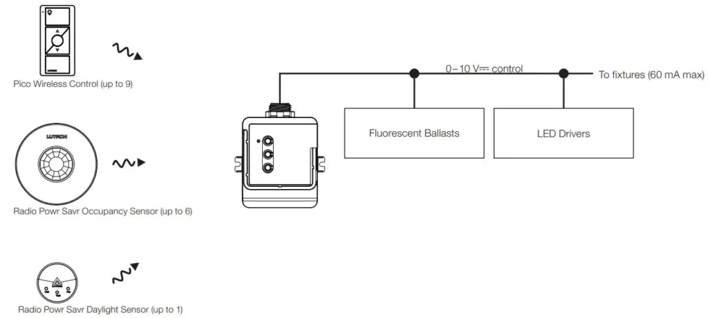
- Controls up to 60 mA of 0 –10 V
 controlled fixtures together
 - Switches up to 5 A total
- 0- 10 V control link automatically sources or sinks to the third party fixtures
- Configurable high- and low-end trim
- Various operating voltages available; refer to model number chart below for details on voltage requirements
- Receives input from up to nine Pico wireless controls, six Radio Power Saver occupancy / vacancy sensors, and one Radio Power Saver daylight sensor
- Utilizes Lutron Clear Connect RF Technology; refer to model number chart below for frequency band data
- Mounts to a US-style junction box through a standard-size knockout
Models Available
NOTE: Contact Lutron for frequency band compatibility for your geographic region if it is not indicated above.
Specifications
Regulatory Approvals
RMJ- and URMJ- models only
- UL Listed
- FCC approved. Complies with the limits for a Class B device, pursuant to Part 15 of the FCC rules
- Complies with requirements for use in other spaces used for environmental air (plenums) per NEC 2014 300.22(C)(3)
- Classified in accordance with CAN / ULC-S142 as discrete product certified for installation in an mishandling space
- CSA or cUL and IC (Canada)
- COFETEL (Mexico) (RMJ- models only)
- NOM (Mexico) (RMJ- models only)
RMN- model - WPC Type Approved (India)
RMK- model - CE (European Union)
- TRA Type Approved (United Arab Emirates) RMP- model
- PSE certified (Japan)Power
- Operating voltage
– RMJ-, URMJ- models: 120 / 277 V~ 50/60 Hz
–RMQ– model: 110 127 / 220 240 V~ 50/60 Hz
–RMM– model: 220 240 V~ 50/60 Hz
–RMK– model: 220 240 V~ 50/60 Hz
–RMN– model: 220 240 V~ 50/60 Hz
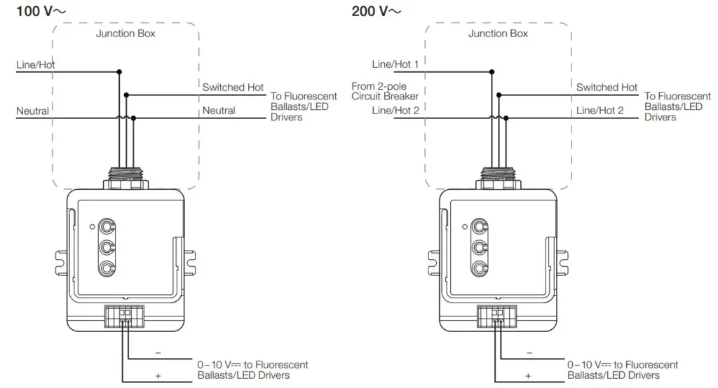
–RMP– model: 100 200 V~ 50/60 Hz
Output Ratings - Switch rating of 5 AX. Rated for resistive or capacitive loads as defined by IEC/EN 60669-2-1
- 0 –10 V control link for 60 mA maximum output, source or sink automatically configures
Other Power Specifications
- Standby power:
240 277 V~ 610 mW 120 V~ 550 mW - BTU/hour when fully loaded: 9
- Works with all ballasts and drivers that provide a current source that is compliant to IEC 60629 Annex E.2, and whose inrush current does not exceed NEMA410 standards for electronic ballast/driver
System Communication - Operates using Clear Connect RF Technology for reliable wireless communication; refer to model number chart on page 1 for frequency band details
- RF range is 30 ft. (9 m)
- Metal ceiling grids must have a 0.12 in (3 mm) gap of non-metal material which extends the entire length of the tile on at least one edge. This is often achieved by foam spacers that are used to prevent tile-to tile rattling.
- Metal ceiling grids which are continuous (with no gap) or those that are interlocked, must have a total surface area that is less than 30 ft2 (81 m2) for each section. The overall space can be larger as long as there are non-metal sections bordering or intersecting the metal sections.
Environment - Ambient operating temperature: 32 °F to 104 °F (0 °C to 40 °C)
- 0% to 90% humidity, non-condensing
- For indoor use only 0 -10 V Control Link
- Communicates with up to 60 mA of fixtures
- Control link is IEC SELV/NEC Class 2
- 0 -10 V control can be installed using NEC Class 1 or Class 2 wiring methods. Alternately, it can be wired to basic or double-insulated devices
- Terminals accept one 18 to 16 AWG (0.75 to 1.5 mm2) solid wire
- Always consult local wiring codes
- Compatible with ANSI E1.3 2001 (R2006), IEC 60929 Annex E
Default Operation - Associated wireless input devices control all connected fixtures together
- Occupancy Sensors:
– Occupied: 100%; Unoccupied: 0% (OFF) - Pico Wireless Controls:
– On: 100%; Favorite Level: 50%; Off: 0% (OFF) - Daylight Sensor: Decreases electric light in response to additional available daylight
Key Design Features - LED status indicator shows load status and provides programming feedback
- Configurable high-end and low-end trim
- Power failure memory: If power is interrupted, connected loads will return to the previous level prior to interruption
- 0 -10 V control misfire protection up to 30 V
- Programming lockout can be enabled for public spaces
- 0 -10 V control can be programmed to be inverted for 10 0 V control
- Daylight override: Pressing the raise button on an associated Pico wireless control will temporarily override daylighting for all fixtures wired to the PowPak Dimming Module with 0 -10 V control
– Daylighting will be re-enabled for all the fixtures wired to the PowPak Dimming Module with 0 10 Control when one of the following occurs: - Two hours have passed since the override.*
- ON, OFF or Preset button has been pressed on a Pico wireless device controlling the fixtures wired to the PowPak Dimming Module with 0 –10 V control.
- All associated Occupancy Sensors have reported unoccupied.
* Each time a daylighting override occurs for any control associated to the PowPak Dimming Module with 0 –10 V– control, the two-hour timer is reset.
Advanced Configurations
Pico Wireless Controls
- Up to nine Pico wireless controls
- Favorite levels can be set for each Pico wireless control
Radio Power Saver Daylight Sensor - The Radio Power Saver daylight sensor will affect all connected ballast and LED drivers equally
- For multiple rows of daylighting, a separate PowPak Dimming Module with 0 –10 V must be used for each daylighting row
Minimum Light Level Setting (optional) - Certain applications, such as hallways, may require that the lights never turn off. For these areas, select the minimum light level option and the load will lower to programed low-end level. Default operation lowers to OFF.
High- and Low-End Trim - High-end and low-end trim affect all connected fixtures equally, and can be configured from the PowPak Dimming Module or from any associated Pico wireless control when unit is not in programming lock-out mode
- Adjustable low-end trim (0% 45%). Trimmable low-end can ensure a stable light level. Some fixtures will flicker or drop out if trimmed too low.
- The maximum light output of connected fixtures can be decreased down to 55% for energy savings in over-lit spaces
Note: The perceived light output of low-end trim may vary between fixture manufacturers and model numbers. For best results, do not mix different ballasts or drivers on the same 0 –10 V circuit. Radio Power Saver Occupancy Sensors - Radio Power Saver occupancy and vacancy sensors control all connected ballasts or drivers
- Pico wireless controls can be used to adjust the Occupied levels of fixtures that they control from 1% to 100% (of output signal) or can make them unaffected by Occupancy events
- Vacancy events (area becomes unoccupied) turn all ballasts and driver models off or to minimum light level
Programming Lockout - Once enabled, all Pico wireless controls can no longer perform programming or set favorite levels
- To change settings, programming lockout must be unlocked by a button combination directly on the PowPak Dimming Module.
System Diagram (RMJ-, URMJ-, RMQ-, and RMM- models)

Wiring Schematic (RMJ-, URMJ-, RMQ-, and RMM- models)

NOTE:
Some applications (in the USA) require the PowPak module to be installed inside an additional junction box. For information about how to perform this installation, visit www.lutron.com, Application Note #423 (P/N 048423). Please consult all local and national electric codes for proper installation methods.
System Diagram (RMP- models)

Wiring Schematic (RMP- models)

System Diagram (RMK- and RMN- models)

Wiring Schematic (RMK- and RMN- models)

* NOTE:
RMK- model PowPak module can be installed in a junction box or marshalling box. Please consult all local and national electric codes for proper installation methods.
Dimensions
Dimensions are shown as: in (mm)

Range Diagram
All wireless transmitters must be installed within 30 ft. (9 m) of the PowPak Dimming Module.

- Metal ceiling grids must have a 0.12 in (3 mm) gap of nonmetal material which extends the entire length of the tile on at least one edge. This is often achieved by foam spacers that are used to prevent tile-to tile rattling.
- Metal ceiling grids which are continuous (with no gap) or those that are interlocked, must have a total surface area that is less than 30 ft2 (81 m2) for each section. The overall space can be larger as long as there are non-metal sections bordering or intersecting the metal sections.
The Lutron Logo, Lutron, Clear Connect, Energi TripPak, Pico, PowPak, and Radio Power Saver are trademarks or registered trademarks of Lutron Electronics Co., Inc. in the US and/or other countries.
All other product names, logos, and brands are property of their respective owners.
