EPEVER MPPT Solar Charge Controller User Manual
EPEVER MPPT Solar Charge Controller User Manual
Thank you for selecting the Tracer BP series MPPT solar charge controller. Please read this manual carefully before using the product and pay attention to the safety information.
Safety Information
- Read all of the instructions in the manual before installation.
- DONOT disassemble or attempt to repair the controller.
- Install external fuse or breaker as required.
- Do disconnect the solar module and fuse/ breakers near to battery before installing or moving the controller.
- Power connections must remain tight to avoid excessive heating from a loose connection.
- Only charge batteries that comply with the parameters of controller.
- Battery connection may be wired to one battery or a bank of batteries.
- Risk of electric shock, the PV and load can produce high voltages when the controller is working.
Overview
The Tracer BP series solar charge controller adopt to the advanced Maximum Power Point Tracking charging methods, it enables the system charging and discharging management to obtain the most radical optimization. Increase the system flexibility, yet lower down the system cost. The controller support a variety of battery, for example sealed, gel, flooded and lithium battery. User can view and modify the working status parameters. It can be widely used on solar home system, traffic signal, solar street light, solar garden lamp, etc. The features are listed below
- Adopt high quality components of ST,IR and Infineon, make sure product using lifespan
- Wide working environment temperature
- Apply to lead-acid battery and lithium battery
- Lithium battery self-activating and low temperature protection function
- Maximum conversion efficiency of 98%
- Advanced Maximum Power Point Tracking (MPPT) technology, with tracking efficiency no less than 99%
- Ultra-fast tracking speed and guaranteed tracking efficiency
- Accurately recognizing and tracking of multiple power points
- PV power limitation function
- Monitoring and setting parameter via Mobile APP, PC Monitor setting software with RS485 communication interface.
- Use of standard Modbus communication protocol for RS485 bus connections, communication protocol compatibility much better
- Connecting the IOT(Internet of Things) module and Cloud Server monitoring software to realize remote monitoring of the multi-machine system
- The RS485 connector can provide power supply
- Aluminum housing for better cooling
- Real-time energy statistics function
- IP68 waterproof degree
Product Features
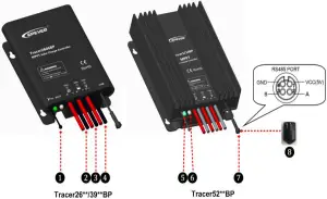
| ① | Temperature Sensor | ⑤ | Charging Status LED indicator |
| ② | PV Positive and Negative Wires | ⑥ | Battery Status LED indicator |
| ③ | Battery Positive and Negative Wires | ⑦ | RS485 waterproof port |
| ④ | Load Positive and Negative Wires | ⑧ | Waterproof cap(Included) |
- The temperature sensor short-circuited or damaged, the controller will be charging or discharging at the default temperature 25 ºC.
- The port can provide the DC power supply of 5VDC/150mA and have the short circuit function
 NOTE: When the RS485 communication port is not working, the
waterproof cap must be installed to prevent water getting in
Wiring
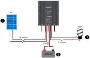
Connection Order
- Connect components to the charge controller in the sequence as shown above and pay much attention to the “+” and “-”.Please don’t insert the fuse or turn on the breaker during the installation. When disconnecting the system, the order will be reserved.
- After power on the controller, check the battery LED indicator on the controller, it will be green. If it’s not green, please refer to chapter 10.
- Connect a fuse in series through battery positive (+) in the circuit and the battery circuit fuse must be 1.25 to 2 times to the rated current. The installed distance is within 150mm.
Load self-test function
The load is ON when the controller power on 10s. After 10s it will restore to set working mode.
LED Indicators
| Indicator | Color | Status | Instruction |

|
Green | On Solid | PV connection normal but low voltage(irradiance) from PV, no charging |
| Green | OFF | No PV voltage(night time) or PV connection problem | |
| Green | Slowly Flashing(1Hz) | In charging | |
| Green | Fast Flashing(4Hz) | PV Over voltage | |

|
Green | On Solid | Normal |
| Green | Slowly Flashing(1Hz) | Full | |
| Green | Fast Flashing(4Hz) | Over voltage | |
| Orange | On Solid | Under voltage | |
| Red | On Solid | Over discharged | |
| Red | Fast Flashing(4Hz) | Battery Overheating Low temperature | |
| Charging(green) and battery indicator(orange)flashing simultaneously | System voltage error※ | ||
- When the battery type is Lithium Battery the controller do not recognize the system voltage automatically.
Load Working Mode
- Manual Mode(Default ON)
- Light ON/OFF
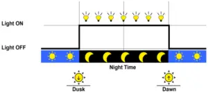
- LightON+Timer

- Real-time Control
Control the load ON/OFF time through setting real-time clock.
NOTE: In the mode of Light ON/OFF and Light ON/Timer, the Load is turned on after 10Min. delay
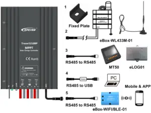
Accessories(optional) and Software
PC Software
www.epever.com Solar Station Monitor
APP Software
- Android phone
www.epever.com Charge Controller(Li) - IPhone
APP Store——EPEVER——EP-01 - MT50 does not support the relevant parameters of lithium battery.
- Specific instructions refer to the list of accessories and software.
Protection
- PV Over Current
The controller will limit battery charging current to the Maximum Battery Current rating. Therefore an over-sized solar array will not operate at peak power. - PV Short Circuit
When PV short circuit is powered on or PV input is short circuit on low-power, the controller will stop charging. Clear it to resume normal operation.
 WARNING: The controller may be damaged, when PV input is short
circuit on high-power. - PV Reverse Polarit
The PV can be reversely connected with a controller when: - Only the PV is connected with the controller;
- The battery is positively connected, and the open-circuit voltage of the PV is lower than 85V(This requirement is only for Tracer26/39/5210BP).
WARNING: Controller will be damaged when the PV array straight
polarity and the actual operation power of the PV array is 1.5 times greater than the rated charge power! - Battery Reverse Polarity
When the PV is not connecting or connecting reversed, fully protection against battery reverse polarity, correct the wire connection to resume normal operation.
WARNING: Controller will be damaged when the PV connection is
correct and battery connection reversed! - Battery Over Voltage
When the battery voltage reaches to the set point of Over Voltage Disconnect Voltage, the controller will stop charging the battery to protect the battery from being over charged to break down - Battery Over Discharge
When the battery voltage reaches to the set point of Low Voltage Disconnect Voltage, the controller will stop discharging the battery to protect the battery from being over discharged to break down - Battery Overheating
The controller detects the environment temperature through the external temperature sensor. If the environment temperature exceeds 65 ºC, the controller will automatically start the overheating protection to stop working, and recover below 55 ºC. - Lithium battery Low Temperature
The temperature sensor is less than the low temperature value, Lithium battery stop charging/discharging. It is higher than the low temperature value, Lithium battery start charging/discharging. - Load Overload
If the load current exceeds the maximum load current rating 1.05 times, the controller will disconnect the load. Overloading must be cleared up through reducing the load and restarting controller - Load Short Circuit
Load will be switched off when load short circuit (≥4 times rated current) happens. Controller will automatically attempt to reconnect load for 5 times. If short circuit protection still exist after controller’s 5 times attempts, user have to clear short circuit ,then restart the controller or wait for one night-day cycle (night time>3 hours) - Temperature sensor break down
If the temperature sensor short-circuited or damaged, the controller will be charging or discharging at the default temperature 25 ºC to prevent the battery damaged from overcharging or over discharged. - High Voltage Transients
The controller is protected against small high voltage transients. In lightning prone areas, additional external suppression is recommended.
Troubleshooting
| Faults | Possible reasons | Troubleshooting |
| LED Charging indicator turn off during daytime when sunshine falls on PV modules properly | PV array disconnection | Confirm that PV and battery wire connections are correct and tight |
|
No LED indicator |
Battery voltage maybe less than 8.5V | Measure battery voltage with the multi-meter. Min.8.5V can start up the controller |
| Battery LED indicator green fast Flashing | Battery over voltage | Check if battery voltage is higher than OVD, and disconnect the PV |
| Battery LED indicator red | Battery over discharged | When the battery voltage is restored to or above LVR point (low voltage reconnect voltage), the load will recover |
| Battery LED indicator red flashing | Battery Overheating | The controller will automatically turn the system off. But while the temperature decline to be below 50ºC, the controller will resume. |
|
Load is not output |
Load Overload① | ①Please reduce the number of electric equipments. ②Restart the controller. ③wait for one night-day cycle (night time>3 hours). |
| Load Short Circuit① | ①Check carefully loads connection, clear the fault. ②Restart the controller. ③wait for one night-day cycle (night time>3 hours). |
①When it is overload or short circuit, the load have 5 times auto-recovery output function, which each times delay respectively 5s, 10s, 15s, 20s, 25s.
Disclaimer
This warranty does not apply under the following conditions:
- Damage from improper use or use in an unsuitable environment.
- PV or load current, voltage or power exceeding the rated value of controller.
- The controller is working temperature exceed the limit working environment temperature.
- User disassembly or attempted repair the controller without permission.
- The controller is damaged due to natural elements such as lighting.
- The controller is damaged during transportation and shipment.
Technical Specifications
| Item Model | Tracer2606BP | Tracer3906BP | Tracer5206BP | Tracer2610BP | Tracer3910BP | Tracer5210BP | Tracer7810BP | |
| Nominal system voltage | 12/24VDC Auto( Lithium battery do not automatic identification system voltage) | |||||||
| Battery input voltage range | 8.5~32VDC | |||||||
| Rated charge/discharge current | 10A | 15A | 20A | 10A | 15A | 20A | 30A | |
| Rated charge power | 130W/12V;260W/24V | 200W/12V;400W/24V | 260W/12V;520W/24V | 130W/12V;260W/24V | 200W/12V;400W/24V | 260W/12V;520W/24V | 390W/12V;780W/24V | |
| Max. PV open circuit voltage | 60V( at minimum operating environment temperature )
46V( at 25℃ environment temperature ) |
100V( at minimum operating environment temperature )
92V( at 25℃ environment temperature ) |
||||||
| MPP Voltage range | ( Battery voltage+2V)~36V | ( Battery voltage+2V)~72V | ||||||
| Battery Type | Lead-acid battery: Sealed(Default) / Gel / Flooded/User; Lithium battery:LiFePO4/ Li-NiCoMn/User | |||||||
| Lead-acid | Equalize Charging Voltage | Sealed :14.6V/Gel:No / Flooded:14.8V/User:9-17V (×2/24V) | ||||||
| Boost Charging Voltage | Sealed :14.4V/Gel:14.2V/Flooded:14.6V/User:9-17V (×2/24V) | |||||||
| Float Charging Voltage | Sealed/Gel/Flooded:13.8V/User:9-17V (×2/24V) | |||||||
| Low Voltage Reconnect Voltage | Sealed/Gel/Flooded:12.6V/User:9-17V (×2/24V) | |||||||
| Low Voltage Disconnect Voltage | Sealed/Gel/Flooded:11.1V/User:9-17V (×2/24V) | |||||||
| Lithiucm | Boost Charging Voltage | LiFePO4:14.5V/ Li-NiCoMn:12.5V / User:9-17V (×2/24V) | ||||||
| Low Voltage Reconnect Voltage | LiFePO4:12.8V / Li-NiCoMn:10.5V / User:9-17V (×2/24V) | |||||||
| Low Voltage Disconnect Voltage | LiFePO4:11.1V / Li-NiCoMn:9.3V / User:9-17V (×2/24V) | |||||||
| Self-consumption | ≤13mA/12V;≤11.5mA/24V | |||||||
| Temperature compensation coefficient | -3mV/℃/2V( Lithium battery don’t have temperature compensation coefficient) | |||||||
| Communication | RS485 | |||||||
| Working environment Tem. | -40℃~+60℃ | -40℃~+50℃ | ||||||
| Enclosure | IP68 | |||||||
| Overall dimension | 124×89×30mm | 150×93.5×32.7mm | 153×105×52.1mm | 124×89×30mm | 150×93.5×32.7mm | 153×105×52.1mm | 153.3×105×52.1mm | |
| Mounting hole size | Φ3.5mm | |||||||
| Mounting dimension | 88×76mm | 120×83mm | 120×94mm | 88×76mm | 120×83mm | 120×94mm | ||
| Power cable | 14AWG(2.5mm2) | 12AWG(4mm2) | 14AWG(2.5mm2) | 12AWG(4mm2) | 10AWG(6mm2) | |||
| Net weight | 0.54kg | 0.74kg | 1.20kg | 0.54kg | 0.74kg | 1.20kg | 1.26kg | |
FAQS
Would the unit be damaged if the battery polarity is reversed?
It is required to connect the battery first, if the battery polarity is reversed in this step, the controller has the protection and would not be damaged. But if the user connects the PV first and then, unfortunately, connects the battery polarity reversed, the controller would be damaged. This is caused by lithium battery characteristics.
Can the lithium battery type be chosen via the LCD and button on the controller?
Yes, the TracerAN series 10-40A charge controller (softwareSV200 or above version ) supports choosing lithium battery type via LCD. But WiFi/Bluetooth module or PC is required if the user wants to customize the voltage setpoints.
Can I set Max. charge current?
No such feature, the only way to limit the Max. charge current is to connect fewer solar panels.
Is this a three stage charger?
An essential setting that is often not available…
What is the operating high temp?
The manual gives an operational ambient temperature range of -25C to 45C, and a storage temperature range of -35C to 80C; the manual also says that if you’re operating outside the permissible ambient range, you need to derate the capacity in service (also, below -20C the LCD panel won’t display).
Can the 4210 model be paired in parallel with the same controller to increase capacity, like the 6415 can (6415 can be connected in up to a set of 8)?
Yes, it can. You can connect two or four 4210AN charge controller to the batteries bank in parallel, but do not share PV Panels. Dedicate a number of PV panels to each controller (Any mppt controller must have a separate array of solar panels).
Does this charge controller cause any amateur radio RFI or noise problems?
Yes to measurable rfi . No to it being a problem. N3SBX. If it were to become a problem just turn it off for weak signal work or build a filter
Why is 99% answers to how many 100w could be on 40a mppt wrong? why manufacturer says depends on actual amps from panels?
It depends on if you are charging 12 volt batteries or a 24 volt battery bank
Are these stackable?
You can connect two or four same Tracer AN charge controller modle to the batteries bank in parallel, but do not share PV Panels. Dedicate a number of PV panels to each controller.
Can you mount this controller so it lies on its side (horizontally on its long-thin side?)
As long it has airflow thru the fins , it should be fine . That is just my guess.
Can this be used for Si02 batteries?
It may be possible. You will definitely have to contact EPEVER directly though. The specifications
for this line of controllers calls out Flooded, Gel, AGM, Li (FePo4), and user.
Is this temank or epever? Description has name as temank. Everything else syates epever.
This is an Epever
Do you need wi fi for this charge controller?
No. All functions are controlled by the remote display.
Can you insert a 4 gauge wire into the PV contacts?
some of the connectors yes but not all
40A says 6awg for power terminals. I have 10 awg coming from solar panels, so do I connect the 10awg to 6awg prior to connecting to unit?
Not necessary! This means that the controller has input terminals that can handle 6awg sized wires
Will the tracer (20 amp) work on AGM batts?
From the manual: “MPPT Charge controller is compatible with Lead-acid batteries, GEL/AGM and Lithium batteries. (AGM battery setting same as GEL parameters, or more accurate parameters follow battery factory advice by User type ) Four load control modes: manual mode, light ON/OFF, light On+ Timer and test mode.”
My 4210AN with 3 panels in parallel putting out upto 33.5 volts does not seem capable of charging the 24v lifepo4 past 26.73v. Should it charge to 28?
You need to adjust the voltage you need go to settings and fix.