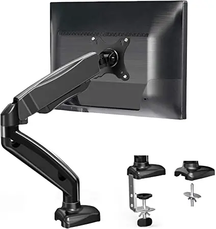
ERGO Monitor Desk Mount
Thank you for choosing this product! We strive to provide you with the best quality products and services in the industry. Should you have any issues, please don’t hesitate to contact at [email protected] (US/CA).
TENSION ADJUSTMENT SHOULD BE DONE ONLY AFTER MOUNT INSTALLATION
Do not adjust tension without monitor.
- Ensure monitor has been attached to the mount.
- Read your monitor box or manual to find out monitor net weigh t.
- Ensure the net weight of monitor (including accessories) is within 17.6 Ibs (8 kg).
Clockwise to reduce tension(carry less weight).
Counter-clockwise to increase tension(carry more weight).
- Please read through these instructions completely before attempting installation. If you do not understand the instructions or have any concerns or questions, please contact customer service at [email protected].
- Check package contents against Supplied Parts and Hardware List to assure that all components were received undamaged. Do not use damaged or defective parts. If you require replacement parts, contact customer service at [email protected].
- Not all parts and hardware included will be used.
- This product contains a high pressure gas spring, fire and percussion prohibited. Also it is strictly prohibited to dismantle without professionals. Please return to the manufacturer or hand over to professional agencies if the product is abandoned.
- Do not use this product for any purpose or in any configuration not explicitly specified in this instruction. We hereby disclaim any liability for injury or damage arising from incorrect assembly, incorrect mounting, or incorrect use of this product.
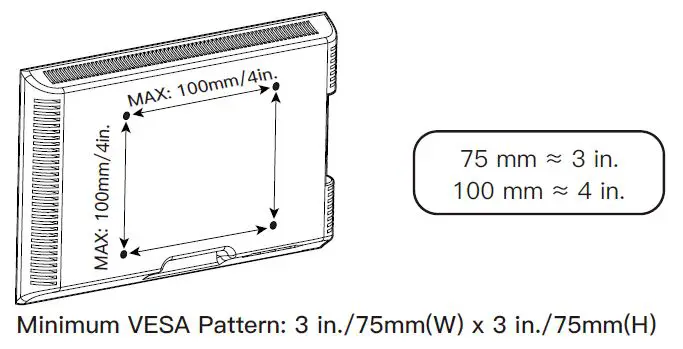
Check the VESA Pattern of Monitor Before the Installation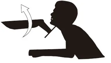
If your monitor VESA is greater than 100 x 100 mm/4 x 4 in. or less than VESA 75 x 75 mm/ 3 x 3 in., this mount is NOT compatible.
If this mount is NOT compatible, please contact customer service at [email protected] to find a compatible mount.
Product Features
Supplied Parts and Hardware List
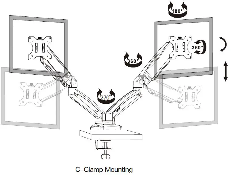
Step 1A For Clamp Mounting
Connect Connecting Plate [B] to Arm Assembly [A]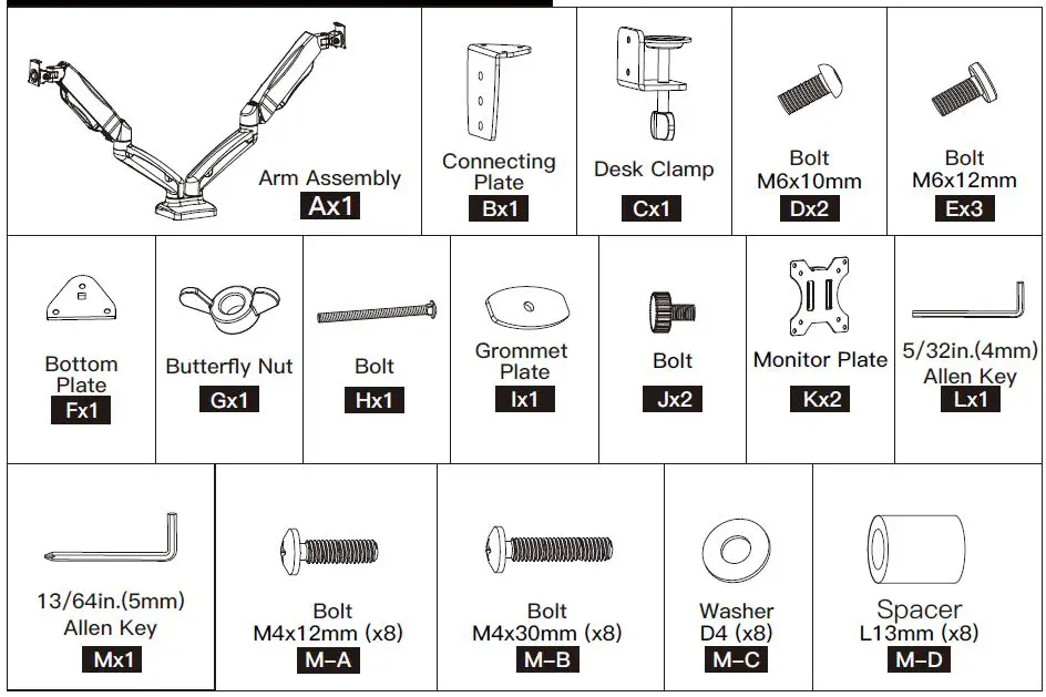 Secure Desk Clamp [C] to Connecting Plate [B] According to the Thickness of the Desktop.
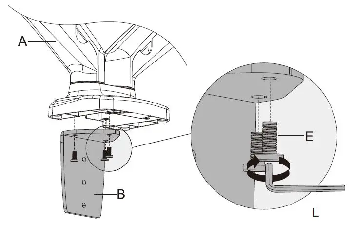 Secure the Mount to Desktop.
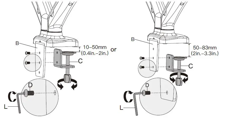
Step 1B For Grommet Mounting
Secure Bottom Plate [F] and Bolt [H] to Arm Assembly [A].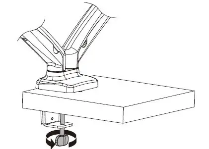
Secure the Mount Assembly to the Desktop.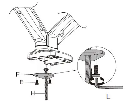
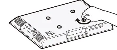
Step 2: Attach the Monitor Plate [K] to the Monitor
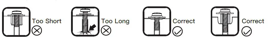
Select Monitor Bolts
Only one bolt size fits your monitor.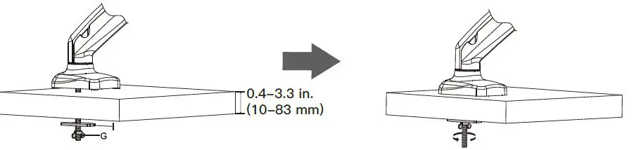
Bolt length: Verify adequate thread engagement with bolts or bolts/spacers combination. We recommend thread engagement by at least 5 turns.
- Too short will not hold the monitor.
- Too long will damage the monitor.
Step 3 Secure the Monitors to Arm Assembly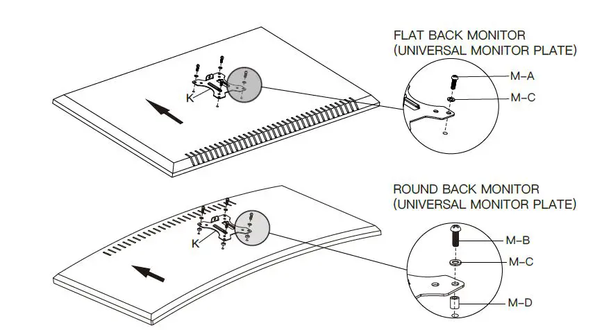
The tension is preset at 4-5kg. After hanging the monitor to the mount, please release the monitor slowly to prevent it from falling suddenly.
Step 4 Adjust the Gas Spring Tension
Be sure to keep the arm in horizontal position during adjustment. Or else, it would be difficult to adjust the mount or damage the mount.
- If the monitor can stay at the desired height by itself, no adjustment needed.
- If the monitor rises up, press the arm to keep it in horizontal position and then use the 13/64in.(5mm) Alley key [M] to turn the bolt clockwise(“-” direction) to reduce tension of the arm only until the monitor can stay at the desired height by itself.
- If the monitor falls down, lift the arm to keep it in horizontal position and then use the 13/64in.(5mm) Alley key [M] to turn the bolt counter-clockwise(“+” direction) to increase tension of the arm only until the monitor can stay at the desired height by itself.
Step 5 Rotation Restriction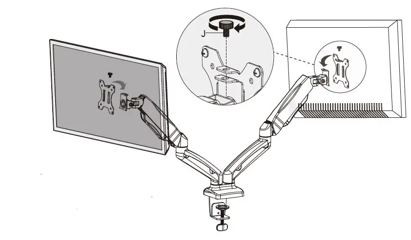
Step 6 Adjustments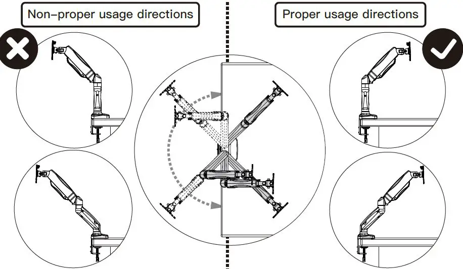
Situation 1: If the monitor can stay at the desired tilt angle by itself, no adjustment needed.
Situation 2: If the monitor can not stay at the desired tilt angle by itself, turn the bolt clockwise or counter-clockwise as shown until the monitor can stay at the desired tilt angle by itself.
Level and Rotation Adjustments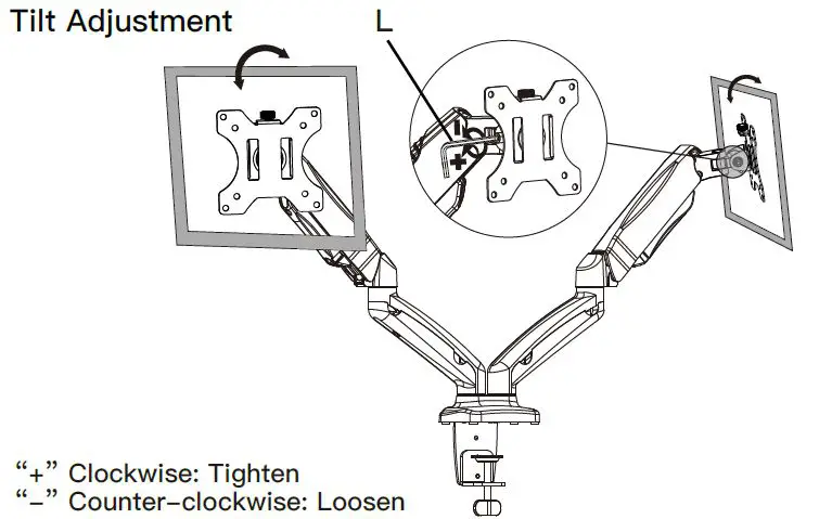
Step 7 Route the Cables Along the Arm Assembly [A]
Detach the cable covers from the arm assembly [A]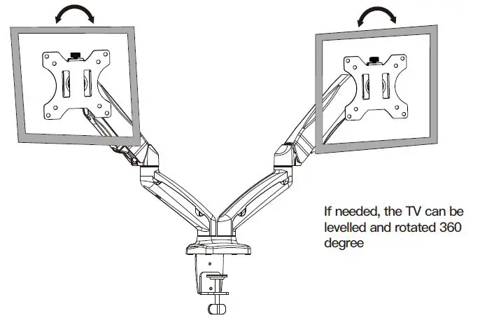
Route the cables along the arm assembly and secure the cable covers to the arm assembly [A].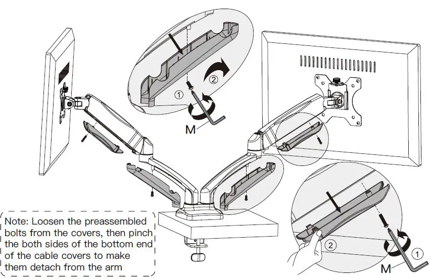
![]()