EVA Logic WiFi Smart Dimmer Switch WF31 User Manual
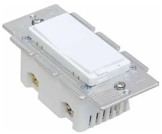
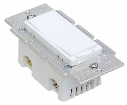
Meet your new smart switch
- Switch x1

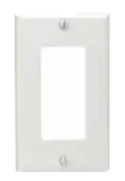
- Faceplate x1
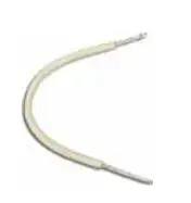
- wiring x1
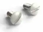
- screws x2
Specifications
- Power: 120V AC, 60Hz
- Indoor use in dry location
- Wireless Frequency: 2.4GHz
- Wireless Srandard: IEEE802.11b/g/n
- Maximum Load: 150W LED, 500 W incandescent (300W with both sides of heat sink tabs off)
- Minimum Load: 15W for LED bulbs
- Range: Up to 100 feet line of sight
- FCC ID:2AQURWF31
- UL: E464831
- For indoor use
Installation
Eva Logik smart switch will turn your switch into a smart one. All you need to do is to do some basic wiring work.
1. Let’s get started.
 We will guide you through the whole wiring process. If you are not sure about the basic wiring work, please call an electrician.
2. Check Wi-Fi signal.

Please make sure that your switch is an area with strong Wi-Fi signal.
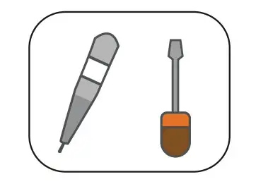
3. Tools

Please prepare a flat head screw driver, a wire stripper and a volt meter. Just in case you might need them.
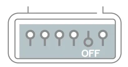
4. Turn off circuit breaker
Find your light control in your circuit breaker and turn it off. Make sure the power is off by flipping your switch several times
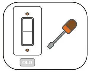
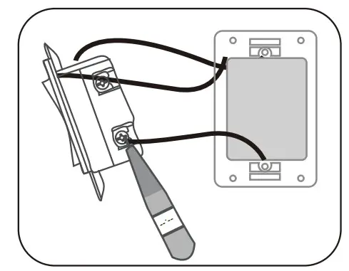
5. Detach old switch.
Unscrew the top and bottom screws of the switch to detach it from the wall.
6. Double check
You can use voltage detector here to make sure there is no power going
through the wires.
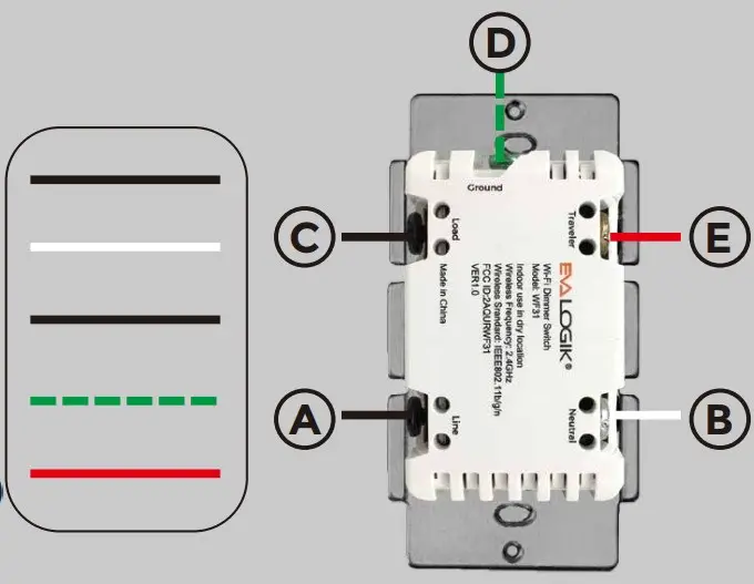
7. Identify the wires.
- LINE (Hot) — Black (connected to power)
- NEUTRAL — White
- LOAD — Black (connected to lighting)
- GROUND — Green/Bare
- TRAVELER — Red/Other (only in 3-way installations) Common
 Wiring Instructions – A Few Quick Reminders
A quick note before we give out the wiring
schematics. Please do not try installing this
device if you are unsure of how electri calcircuits operate within your home. As exciting
as it is to have a smart switch installed, it can be dangerous and even life-threatening if you do not install this correctly. Please consult a qualified electrician if necessary. With that said, here are a few other warnings we’d like to point out for your safety:
- Single switch

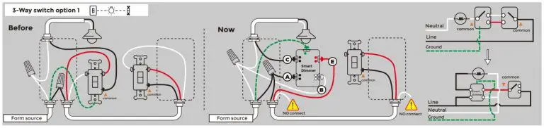
- 3-Way switch option 1

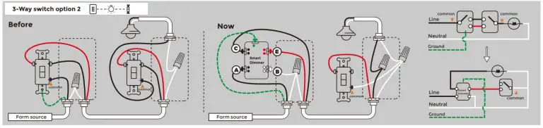
- 3-Way switch option 2
Manual Control
- Tapx1( Top rocker) : turn on the light(the last brightness level) Press and hold (Top rocker): add brightness
- Tapx1(bottom rocker): turn off the light Press and hold (bottom rocker): reduce brightness.
- Tapx3(Top or bottom rocker) then hold 10s until the Wi-Fi status LED Blinks rapidly to initiate App- Config Mode. Solid 10s & Flash 1 time: Operation again, Until success Press The Air-Gap Switch: when changing bulbs to cut off power to the switch for your safety and shock prevention.
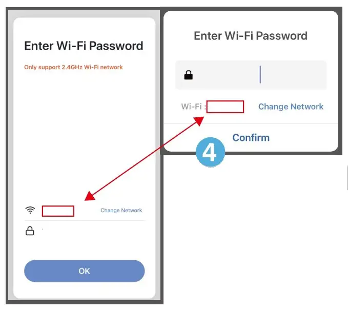
APP Connection


- Please scan the QR code to download the application “Smart Life”.
- If you cannot download Smart Life app, please search “Smart Life” on Google Play (for Android phone) or Apple Store (for iOS phone) to download. QR code Smart Life After you download the Smart Life App and register a new account, please follow the instructions below to set up your smart switch.
- The smart switch can be also used with Amazon Echo and Google Home. Please scan the QR code below and follow the instructions if you have any trouble pairing with them.


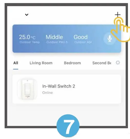
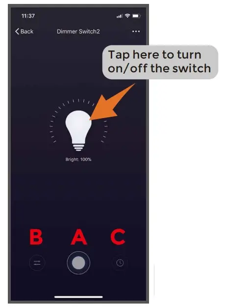
- Tap “ A ” to turn on/off the light.
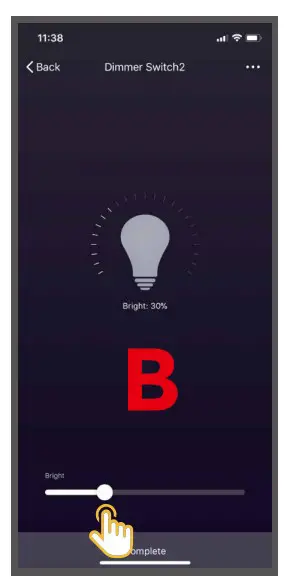
- Tap “ B ” to adjust the brightness of the light.
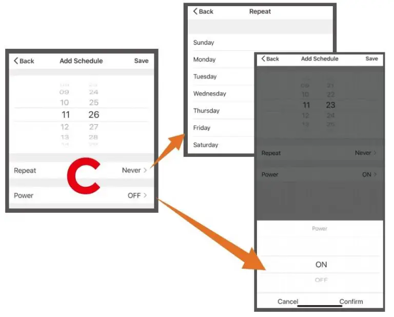
- Tap “ C ” to set a timer to the switch.
Remove Device
Note:
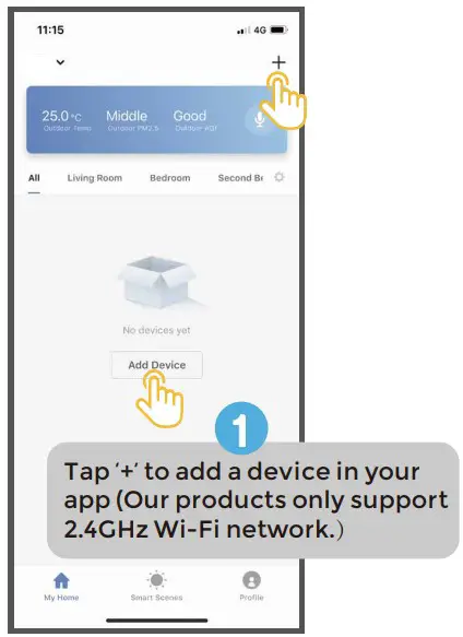
- Our products only support 2.4GHz Wi-Fi network.
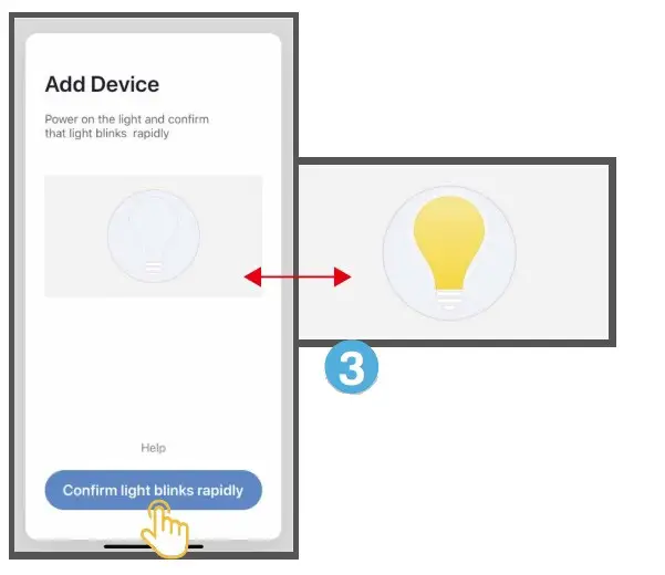
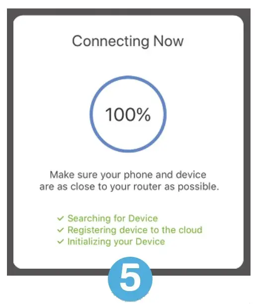
- Please operate quickly when ED indicator blinks rapidly.
- When indicator flash enters the network, complete standard operation within 30s
- Flashing slowly enters AP Mode. (select “AP Mode” follow the default procedure)
FCC / IC
This device complies with part 15 of the FCC and Industry Canada license-exempt RSS standard(s). Operation is subject to the following two conditions:
- this device may not cause harmful interference, and (2) this device
must accept any interference received, including interference that
may cause undesired operation.
FCC NOTE: The manufacturer is not responsible for any radio or TV interference caused by unauthorized modifications to this equipment. Such modifications could void the user’s authority to operate the equipment.
- Reorient or relocate the receiving antenna.
- Increase the separation between the equipment and receiver.
- Connect the equipment into an outlet on a circuit different from that to which the receiver is connected.
- Consult the dealer or an experienced radio/TV technician for help
NOTE: This equipment has been tested and found to comply with the limits for a Class B digital device, pursuant to Part 15 of the FCC Rules. These limits are designed to provide reasonable protection against harmful interference in a residential installation. This equipment generates, uses and can radiate radio frequency energy and, if not installed and used in accordance with the instructions may cause harmful interference to radio communications. However, there is no guarantee that interference will not occur in a particular installation. If this equipment does cause harmful interference to radio or television reception, which can be determined by turning the equipment off and on, the user is encouraged to try to correct the interference by one or
more of the following measures:
Important note: To comply with the FCC RF exposure compliance requirements, no change to the antenna or the device is permitted. Any change to the antenna or the device could result in the device exceeding the RF exposure requirements and void user’s authority to operate the device.
 CAUTION – PLEASE READ!
This device (WF31) is intended for installation in accordance with the National Electric Code and local regulations in the United States, or the Canadian Electrical Code and local regulations in Canada. If you are unsure or uncomfortable about performing this installation consult a qualified electrician.
WARNING – SHOCK HAZARD
TURN OFF THE POWER to the circuit for the switch and lighting fixture at the service panel (circuit breaker) prior to installation.
ALL WIRING CONNECTIONS MUST BE MADE WITH THE POWER OFF to avoid personal injury and/or damage to the switch.
OTHER WARNINGS
- Risk of Fire
- Risk of Electrical Shock
- Risk of Burns