EverStart PPS1CWE Maxx 1000 Amp Battery Jump Starter with Wireless Charging

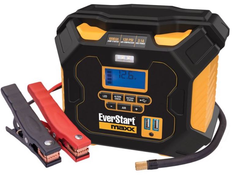
FEATURES


- Carry Handle
- Wireless Charging Pad
- LED Area Light
- LCD Screen
- LED Light Power Button
- Decrease Compressor Pressure Control Button (–)
- Boost Cable
- Alternator Check Button
- Compressor Power Button
- Wireless Charging Button
- USB Power Button
- Increase Compressor Pressure Control Button (+)
- USB Ports with USB Power/Fault Indicators
- AC Charging Port
- Alternator Check Button
- Compressor Power Butto
- Wireless Charging Butt
- USB Power Butto
- Increase Compressor Pressure Control Button (+)
- USB Ports with USB Power/Fault Indicators
- AC Charging Port
LCD DISPLAY DETAIL

SAFETY GUIDELINES DEFINITIONS
DANGER
Indicates an imminently hazardous situation which, if not avoided, will result in death or serious injury.
WARNING
Indicates a potentially hazardous situation which, if not avoided, could result in death or serious injury.
CAUTION
Indicates a potentially hazardous situation which, if not avoided, may result in minor or moderate injury and/or property damage.
RISK OF UNSAFE OPERATION
When using tools or equipment, basic safety precautions should always be followed to reduce the risk of personal injury. Improper operation, maintenance or modification of tools or equipment could result in serious injury and property damage. There are certain applications for which tools and equipment are designed. Manufacturer strongly recommends that this product NOT be modified and/or used for any application other than for which it was designed. Read and understand all warnings and operating instructions before using any tool or equipment.
IMPORTANT SAFETY INSTRUCTIONS
GENERAL SAFETY WARNINGS AND INSTRUCTIONS
- Avoid dangerous environments. Don’t use appliances in damp or wet locations. Don’t use appliances in the rain.
- Keep children away. All visitors should be kept at a distance from work area.
- Dress properly. Do not wear loose clothing or jewelry. They can be caught in moving parts. Rubber gloves and substantial, non-skid footwear are recommended when working outdoors. Wear protective hair covering to contain long hair.
- Store idle appliance indoors. When not in use, appliances should be stored indoors in a dry and high or locked-up place – out of reach of children.
- Don’t abuse cord. Never carry appliance by cord or yank it to disconnect from receptacle. Keep cord from heat, oil, and sharp edges.
- Disconnect appliances. Disconnect the appliance from the power supply when not in use, before servicing, and when changing accessories.
- Ground Fault Circuit Interrupter (GFCI) protection should be provided on the circuits or outlets to be used. Receptacles are available having built in GFCI protection and may be used for this measure of safety.
- Use of accessories and attachments. The use of any accessory or attachment not recommended for use with this appliance could be hazardous. Refer to the accessory section of this manual for further details.
- Stay alert. Use common sense. Do not operate this equipment when you are tired or impaired.
- Check for damaged parts. Any part that is damaged should be replaced by the manufacturer before further use. Do not use tool if switch does not turn it on and off.
- Contact the manufacturer at 1-877-571-2391 for more information.
- Do not operate this appliance near flammable liquids or in gaseous or explosive atmospheres. Motors in these tools normally spark, and the sparks might ignite fumes.
- Never submerge this unit in water; do not expose it to rain, snow or use when wet.
- To reduce risk of electric shock, disconnect the unit from any power source before attempting maintenance or cleaning. Turning off controls without disconnecting will not reduce this risk.
- This equipment employs parts switches, relays, etc that produce arcs or sparks. Therefore, if used in a garage or enclosed area, the unit MUST be placed not less than 18 inches above the floor.
SPECIFIC SAFETY INSTRUCTIONS FOR CHARGING THIS UNIT
IMPORTANT
This unit is delivered in a partially charged state. Charge the unit with the AC charging adapter for a full 20 hours before using for the first time. To recharge this unit, use only the supplied AC charger. All power switches should be in the OFF position when the unit is charging or not in use. Make sure all switches are in the OFF position before connection to a power source or load.
Extension cords
Use of improper extension cord could result in a risk of fire and electric shock. When using an extension cord, make sure that the pins of the extension cord are the same number, size and shape as those in the charger; and be sure to use one heavy enough to carry the current your product will draw. An undersized cord will cause a drop in line voltage resulting in loss of power and overheating. The following table shows the correct size to use depending on cord length and nameplate ampere rating. If in doubt, use the next heavier gauge. The smaller the gauge number, the heavier the cord.

When an extension cord is used, make sure that the pins of extension cord are th e same number, size and shape as those in the charger the extension cord is properly wired and in good electrical condition, the wire size is large enough for the AC rating of the charger.
CAUTION
To reduce the risk of injury or property damage: Pull the extension cord by the plug rather than the cord when disconnecting from the 120 volt AC charging port or the AC outlet.
SPECIFIC SAFETY INSTRUCTIONS FOR WIRELESS CHARGING
CAUTION To reduce the risk of property damage
Do not attempt to use the Jump-Starter or Compressor when using the Wireless Charging function. Place the appliance in the center of the Wireless Charging Pad.
SPECIFIC SAFETY INSTRUCTIONS FOR JUMP STARTERS
Do not use the unit for charging dry-cell batteries that are commonly used with home appliances. These batteries may burst and cause injury to persons and damage property. Use the unit for charging/boosting a lead-acid battery only. It is not intended to supply power to a low-voltage electrical system other than in a starter-motor application.• Use of an attachment not supplied, recommended or sold by manufacturer specifically for use with this unit may result in a risk of electrical shock and injury to persons.
WARNING Risk of explosive gases
Working in the vicinity of a lead acid battery is dangerous. Batteries generate explosive gases during normal battery operation. For this reason, it is of the utmost importance that each time before using the jump-starter you read this manual and follow instructions exactly. To reduce the risk of battery explosion, follow these instructions and those published by the battery manufacturer and manufacturer of any equipment you intend to use in the vicinity of the battery. Review cautionary markings on these products and on the engine.
CAUTION
To reduce the risk of injury or property damage.
NEVER ATTEMPT TO JUMP-START OR CHARGE A FROZEN BATTERY
- Vehicles that have on-board computerized systems may be damaged if vehicle battery is jump-started. Before jump-starting, read the vehicle’s owner’s manual to confirm that external-starting assistance is suitable.
- When working with lead acid batteries, always make sure immediate assistance is available in case of accident or emergency.
- Never smoke or allow a spark or flame in vicinity of vehicle battery, engine or power station.
- Stay clear of fan blades, belts, pulleys, and other parts that can cause injury to persons.
- Remove personal metal items such as rings, bracelets, necklaces and watches when working with a lead acid battery. A lead acid battery can produce a short circuit current high enough to weld a ring, or similar metal object, to skin, causing a severe burn.
- Do not wear vinyl clothing when jump-starting a vehicle. Friction can cause dangerous static-electrical sparks.
- Be extra careful to avoid dropping a metal tool onto the battery. It might spark or short-circuit the battery or another electrical part and could cause an explosion.
- Jump-start procedures should only be performed in a safe, dry, well-ventilated area.
- Always store battery clamps when not in use. Never touch battery clamps together. This can cause dangerous sparks, power arcing and/or explosion.
- When using this unit close to the vehicle’s battery and engine, stand the unit on a flat, stable surface, and be sure to keep all clamps, cords, clothing and body parts away from moving vehicle parts.
- Never allow red and black clamps to touch each other or another common metal conductor this could cause damage to the unit and/or create a sparking/explosion hazard.
- If the clamps are connected incorrectly with regard to polarity, the backlit LCD screen will display the Battery Status Icon, Battery Voltage Indicator, and the Clamp Icons.
- The Alarm Icon, the + and – signs and the Reverse Polarity Icons will flash and the unit will sound a continuous alarm until the clamps are disconnected.
- Disconnect the clamps and reconnect to battery with correct polarity.
- Always disconnect the negative (black) jumper cable first, followed by the positive (red) jumper cable, except for positive grounded systems.
- Do not expose battery to fire or intense heat since it may explode. Before disposing of the battery, protect exposed terminals with heavy-duty electrical tape to prevent shorting (shorting can result in injury or fire.
- Place this unit as far away from the battery as cables permit.
- Never allow battery acid to come in contact with this unit.
- Do not operate this unit in a closed area or restrict ventilation in any way.
- This system is designed to be used only on vehicles with a 12 volt DC battery system.
- Do not connect to a 6 volt or 24 volt battery system.
- This system is not designed to be used as a replacement for a vehicular battery.
- Do not attempt to operate a vehicle that does not have a battery installed.
- Excessive engine cranking can damage a vehicle’s starter motor. If the engine fails to start after the recommended number of attempts, discontinue jump-start procedures and look for other problems that may need to be corrected.
- Do not use this jump starter on a watercraft. It is not qualified for marine applications.
- Although this unit contains a non spillable battery, it is recommended that unit be kept upright during storage, use and recharging.
- To avoid possible damage that may shorten the unit’s working life, protect it from direct sunlight, direct heat and/or moisture.
SPECIFIC SAFETY INSTRUCTIONS FOR THE USB POWER PORTS
- Do not insert foreign objects into the USB Power Ports.
- Do not attach USB hubs or more than one personal electronic device to each USB Power Port.
- Do not use this unit to operate appliances that require more than 3.1 amps in total to operate from the USB power ports.
SPECIFIC SAFETY INSTRUCTIONS FOR COMPRESSORS WARNING – BURST HAZARD:
- Bursting articles can cause serious injury.
- Carefully follow instructions on articles to be inflated.
- Never exceed the recommended pressure listed in instructions on articles to be inflated. If no pressure is given, contact article manufacturer before inflating.
- Monitor the pressure at all times on the pressure gauge.
- To reduce the risk of injury or property damage:
- Never leave the compressor unattended while in use.
- Do not operate compressor continuously for longer than approximately 10 minutes, depending on ambient temperatures, as it may overheat. This could damage the compressor.
FIRST AID
When working with lead acid batteries, always make sure immediate assistance is available in case of accident or emergency. Always have protective eyewear when using this product. Contact with battery acid may cause blindness and/or severe burns. Be aware of first aid procedures in case of accidental contact with battery acid. Have plenty of fresh water and soap nearby in case battery acid contacts skin.
WARNING
Battery fluid is a diluted sulphuric acid and may cause personal injury or damage to property. In case of skin or eye contact, follow the instructions below.
Skin
If battery acid comes in contact with skin, rinse immediately with water, then wash thoroughly with soap and water. If redness, pain, or irritation occurs, seek immediate medical attention.
Eyes
If battery acid comes in contact with eyes, flush eyes immediately, for a minimum of 15 minutes and seek immediate medical attention.
LCD
liquid crystal display: If liquid crystal comes in contact with your skin: Wash area off completely with plenty of water. Remove contaminated clothing. If liquid crystal gets into your eye: Flush the affected eye with clean water and then seek medical attention. If liquid crystal is swallowed: Flush your mouth thoroughly with water. Drink large quantities of water and induce vomiting. Then seek medical attention.
OVERVIEW
Common Actions and Unit Responses
The following actions turn the unit on and activate the LCD screen.
| Press the LED Area Light Power Button. | A beep will sound and the Area Light will turn on. The backlight will turn on for 10 seconds only. The LCD screen will continue to display the Battery Status Icon and Battery Voltage Indicator. The unit remains on until the LED Area Light Power Button is pressed again to turn it off. |
| PresstheAlternatorCheckButton. | A beep will sound and the backlit LCD screen will display the Battery Status Icon, and the Alternator Icon will flash. The unit remains on until the Alternator Check Button is pressed again to turn it off. |
| Press the Wireless Charging Button. | A beep will sound. The backlit LCD screen will display the flashing Wireless Charging Indicator. The unit remains on until the button is pressed again to turn it off, or the unit does not detect an appliance such as a mobile phone for 3 minutes. |
| Press the USB Power Button. | A beep will sound and the backlight will turn on for 10 seconds (only). The LCD screen will display the Battery Status Icon, Battery Voltage Indicator, and the USB Icon; and the USB Power/Fault Indicators will light solid blue indicating the two USB Ports are active. The unit remains on until the USB Power Button is pressed again to turn it off. |
| Press the Compressor Power Button. Portable Compressor section. | A beep will sound and the backlit LCD screen will display the Battery Status Icon, XXX PSI and the Compressor Icon. If no further actions are taken after 1 minute, the unit will display the Battery Status Icon and Battery Voltage Indicator for 10 seconds before automatically turning off. |
Model number PPS1CWE
| Whenever the clamps are properly connected to a battery | A beep will sound and the backlit LCD screen will display the Battery Status Icon, Battery Voltage
Indicator, the Clamp Icons, and the + and – signs, as well as the flashing Jump Starter Icon. The unit remains on until the clamps are disconnected from the battery. |
| If the red and black clamps touch each other | The backlit LCD screen will display the Battery Status Icon and Battery Voltage Indicator. The Clamp Icons, + and – signs and the Alarm Icon will flash. The unit will sound a two-second warning every ten seconds continuously until the clamps are separated. |
| If the clamp connections to the battery’s positive and negative terminals are reversed | The backlit LCD screen will display the Battery Status Icon, Battery Voltage Indicator, and the Clamp Icons. The Alarm Icon, the + and signs and the Reverse Polarity Icons will flash and the unit will sound a warning continuously until the clamps are disconnected from the battery. |
| When the unit is charging or recharging using the supplied Charging Adapter | The backlight will turn on for 10 seconds only. The LCD screen will continue to display the Battery Status Icon and Battery Voltage Indicator. The bars on the Battery Status Icon will change from empty to solid bottom to top repeatedly. |
Note: The unit will automatically power off once ALL the functions are turned off.
VIEWING BATTERY STATUS
The Battery Status Icon and Battery Voltage Indicator indicate the battery charge level as follows.

- If the battery charge level is at full capacity, four solid bars will display.
- If the battery is partially charged, two or three solid bars will display.
- If the battery is nearly empty, one solid bar will display. The unit should be charged at this time.
- If the battery is completely empty, four blank bars will display. The unit MUST be charged at this time or the unit’s built-in low voltage protection will activate. The empty
- Battery Status Icon will flash for a short period of time before automatic shut down. The unit will not operate until the battery is recharged.
CHARGING/RECHARGING
Lead acid batteries require routine maintenance to ensure a full charge and long battery life. All batteries lose energy from self-discharge over time and more rapidly at higher temperatures. Therefore, batteries need periodic charging to replace energy lost through self-discharge. When the unit is not in frequent use, manufacturer recommends the battery should be recharged at least every 30 days and after each use.
IMPORTANT CHARGING NOTES
This unit is delivered in a partially charged state – you must fully charge it before using it for the first time. Initial AC charge should be for 20 hours or until the Battery Status Icon shows 4 solid bars. Recharging the battery after each use will prolong battery life; frequent heavy discharges between recharges and/or overcharging will reduce battery life.3. Make sure all other unit functions are turned off during recharging, as this can slow the recharging process.
CAUTION
Risk of property damage: Failure to keep the battery charged will cause permanent damage and result in poor jump starting performance.
IMPORTANT
If you know the unit is discharged, but the battery icon displays four solid bars as if the unit is fully charged when connected to a charging power source, this may be due to the internal battery having high impedance. Manufacturer suggests leaving the unit charging for a period of 20 hours using the supplied AC charger before use.
PROCEDURE
Insert the barrel connector of the AC charging adapter into the AC charging port on the front of the unit (refer to Fig. 2 to locate). Insert the plug end into a (powered)
standard North American 120 volt 60Hz outlet. When the unit is properly connected to an AC power source, the LCD screen will display the following

The bars on the Battery Status Icon represent the charge level of the unit’s internal battery. The bars on the Battery Status Icon will change from empty to solid
bottom to top repeatedly to indicate the unit is charging. The backlight will turn on for 10 seconds (only). Charge for approximately 20 hours or until the Battery Status Icon shows 4 solid bars. When charging is complete, disconnect the AC charging adapter first unplug the adapter from the AC power source, then disconnect the barrel connector from the unit.
WIRELESS CHARGING
The built-in Wireless Charging feature is suitable for most appliances with a Wireless Charging function. Before proceeding, check the unit’s battery status on the LCD screen. Four solid bars in the battery icon indicates a full battery. When the battery level is nearly empty with only one solid bar, the unit MUST be recharged before use or the unit’s built-in low voltage protection will activate. The empty Battery Status Icon will flash for a short period of time before automatic shut down.
CAUTION
To reduce the risk of property damage: Do not attempt to use the Jump Starter or Compressor when using the Wireless Charging function.
IMPORTANT NOTE
If the unit does not detect an appliance for 3 minutes, the Wireless Charging function will shut down automatically.
PROCEDURE
Press the Wireless Charging Button to turn on wireless charging. A beep will sound, the LCD screen will continuously display the following

ready to use. Place the appliance to be charged in the center of the Wireless Charging Pad for maximum charging efficiency. When charging is complete, press the Wireless Charging Button to turn off the Wireless Charging feature.
IMPORTANT
Make sure the Wireless Charging function is turned off when the unit is being recharged or stored. Some appliances may not charge or operate with this unit.
JUMP STARTER
IMPORTANT
All features must be turned off with the exception of the area light when jump-starting. The unit is intended to be used only in the upright position. The unit must be kept upright during use.
Model number PPS1CWE
To reduce the risk of serious injury or property damage. Follow all safety instructions found in the Specific Safety Instructions for Jump Starters.
- If the clamps are connected incorrectly with regard to polarity, the unit will sound a continuous alarm until the clamps are disconnected. The backlit LCD Screen will
display the Battery Status Icon, the Battery Voltage Indicator and the Clamp Icons.The + and – signs above the Clamp Icons, the Reverse Polarity Icons and the Alarm
Icon will flash. The backlit LCD screen will display the following.

- Disconnect the clamps and reconnect to battery with correct polarity.
- Never touch red and black clamps together. This can cause dangerous sparks, power arcing, and/or explosion. If the red and black clamps touch each other, the unit
will sound a continuous two-second alarm every ten seconds until the clamps are separated. The backlit LCD screen will display the following

- The Battery Status Icon and Battery Voltage Indicator light solid. The Alarm Icon.
- Clamp Icons and the + and – signs will flash. Immediately separate the clamps and do not allow them to touch again.
- If the unit is overheated during the jump starting process, the thermal protection wil activate and the backlit LCD screen will display the following

- The Battery Status Icon and Battery Voltage Indicator light solid. The alarm icon and Jump Starter Icon will flash. Allow the unit to cool for 10-30 minutes before use.
- Always disconnect the negative (black) jumper cable first, followed by the positive (red) jumper cable, except for positive grounded systems.
PROCEDURE
Take the following steps, observing all cautions and warnings.
- Turn off vehicle ignition and all accessories (radio, A/C, lights, connected cell phone chargers, etc.). Place vehicle in “park” and set the emergency brake.
- There is a Boost Cables Connector at the end of the clamps. The slot that it plugs into is located on the back of the unit. Refer to the “Features” section to locate.
Plug the Boost Cables Connector into the Clamp Connection Slot. - Connect the red clamp first, then the black clamp.
- Procedure for jump-starting a NEGATIVE GROUNDED SYSTEM (negative battery terminal is connected to chassis) (MOST COMMON)
- Connect positive (+) red clamp to vehicle battery’s positive terminal.
- Connect negative (–) black clamp to chassis or a solid, non-moving, metal vehicle component or body part. Never clamp directly to negative battery terminal or moving part. Refer to the automobile owner’s manual.
- Procedure for jump-starting POSITIVE GROUND SYSTEMS. In the rare event that the vehicle to be started has a Positive Grounded System (positive battery
terminal is connected to chassis.- Connect negative (–) black clamp to vehicle battery’s negative terminal.
- Connect positive (+) red clamp to vehicle chassis or a solid, non-moving, metal vehicle component or body part. Never clamp directly to positive battery terminal or moving part.
- When the clamps are connected properly, the backlit LCD screen will display the following to indicate the unit is ready to jump start

The Battery Status icon, Battery Voltage Indicator, Clamp Icons and the + and– signs light solid. The jump starter icon will flash to indicate the clamps are properly
connected. Turn on the ignition and crank the engine in 5-6 second bursts until engine starts. The backlit LCD screen will display the following

The Battery Status Icon, the Battery Voltage Indicator, Clamp Icons and the + and– signs light solid to indicate the unit is jump-starting. The Jump Starter Icon
flashes. The Jump Starter Icon lights solid if vehicle is started. Disconnect the negative (–) engine or chassis clamp first, then disconnect the positive (+) battery clamp.
NOTE: If the unit is malfunctioning after jump start procedure, please recharge the unit with the supplied AC charger to reset the unit.
IMPORTANT
When the unit is not in use, detach the Boost Cables Connector from the Clamp Connection Slot and store in a safe place. Always turn the unit off when not in use. Recharge this unit fully after each use.
CAUTION
To reduce the risk of property damage. Remember to disconnect the clamps from the power station and store in a dry, safe location when not in use. Vehicles that have on-board computerized systems may be damaged if vehicle battery is jump started. Before jump-starting this type of vehicle, read the vehicle manual t confirm that external starting assistance is advised. Excessive engine cranking can damage the vehicle‘s starter motor. If the engine fails to start after the recommended number of attempts, discontinue jump-start procedure and look for other problems that need to be corrected. If vehicle fails to start, turn off the ignition, disconnect the jump-start system’s leads and contact a qualified technician to investigate why the engine did not start.
ALTERNATOR CHECK
Set up the unit, connect the battery clamps and connect to the battery following steps 1 through 5 under Procedure in the Jump Starter.
IMPORTANT NOTES
The unit may detect that the alternator is out of typical voltage range because someone has added a number of accessory loads on the charging system, thereby
increasing current demand from the alternator. MAKE SURE THAT THE ALTERNATOR IS RATED TO SUPPORT THE APPLICATION. This check may not be accurate for every make, manufacturer and model of vehicle. Check only 12 volt systems.
PART 1
No Load (turn OFF all vehicle’s accessories): The vehicle battery must be fully charged before testing the alternator. Run the engine long enough to achieve normal idle speed
and verify there is a no-load voltage. Press the Alternator Check Button to start the check. The backlit LCD screen will display the following to indicate the unit is analyzing the alternator

the following

The Battery Status Icon, Alternator Icon, and “ALT GOOD” will light solid. If the unit detects that the alternator is out of typical voltage range, the backlit LCD
screen will display the following

The Battery Status Icon, Alternator Icon and “ALT” will light solid. The Fault Icon will flash. Press the Alternator Check Button again to stop the test and turn off the unit.
PART 2
Under Load (accessories ON): Next, load the alternator by turning on as many accessories as possible except for A/C and Defrost. Press the Alternator Check Button to start the check. The backlit LCD screen will display the following to indicate the unit is analyzing the alternator

The Battery Status Icon will light solid and the Alternator Icon will flash. If the unit detects that the alternator is good, the backlit LCD screen will display the following

The Battery Status Icon, Alternator Icon, and ALT GOOD will light solid. If the unit detects that the alternator is out of typical voltage range, the backlit LCD screen will display the following

The Battery Status Icon, Alternator Icon and “ALT” will light solid. The Fault Icon will flash. Press the Alternator Check Button again to stop the test and turn off the unit.
IMPORTANT
Always turn the unit off when not in use. Recharge this unit fully after each use.
CAUTION
To reduce the risk of property damage
Remember to disconnect the clamps from the power station and store in a dry, safe location when not in use.
PORTABLE COMPRESSOR
The built-in 12 volt DC compressor is the ultimate compressor for all vehicle tires, trailer tires and recreational inflatables. A nozzle adaptor is supplied that screws onto the end
of the Sure Fit nozzle at the free end of the compressor hose. The compressor hose with tire fitting is stored in the hose storage groove on the rear of the unit. The Compressor Power Button and Increase + and Decrease – Compressor Pressure Control Buttons are located on the control panel on the front of the unit. Before proceeding, check the unit’s battery status on the LCD screen. Four solid bars in the battery icon indicates a full battery. When the battery level is nearly empty with only one solid bar, the unit MUST be recharged before use or the unit’s built-in low voltage protection will activate. The empty Battery Status Icon will flash for a short period of
time before automatic shut down. The compressor is capable of inflating up to 120 pounds per square inch (PSI) pressure. Return hose to the hose storage groove after use.
To reduce the risk of serious injury or property damage.
CAUTION
To reduce the risk of serious injury or property damage
When the compressor is operated at a low PSI, the unit may start in low and gradually rev up. When the compressor is operated at higher PSIs, the unit may operate normally for several minutes, then rev down for a few minutes before returning to normal operation. This feature protects the unit from overheating during normal use. In any event, do not operate compressor continuously for longer than 10 minutes, as it may overheat. This could damage the compressor. If the compressor must be operated for longer periods every 10 minutes press the Compressor Power Button to turn the compressor off, then restart after a cooling down period of approximately 30 minutes. In any event, the
compressor will automatically shut down after operating continuously for 10 minutes.
INFLATING TIRES OR PRODUCTS WITH VALVE STEMS
Screw the Sure Fit nozzle onto the valve stem. Do not overtighten. Press the Compressor Power Button. A beep will sound and the backlit LCD screen will display the following

The Compressor Icon will light and the digital display will alternately show the flashing pre-set psi value (that was last set by the compressor pressure control buttons and the current pressure of the item being inflated (which will light solid. Press the + and – Pressure Control Buttons to set the desired pressure from a range pre set values between 3 and 120 which will display on the backlit LCD screen. The unit will sound a beep with each press of the buttons holding the button speeds up the upward or downward value selection. Once the desired pressure has been entered, release the button and the flashing digital display will show the new selected pressure, as follows

Icon will flash and the digital display will only show the current pressure value which will light solid) to indicate the compressor is activated. Monitor the pressure on the LCD screen.
IMPORTANT NOTE
To interrupt during inflation, press the Compressor Power Button again. When desired pre-set pressure is reached, the compressor will automatically stop. Press the Compressor Power Button again to turn off the unit. Unscrew and remove the Sure Fit® nozzle from the valve stem. Allow the unit to cool, then recharge before storing away. Store the compressor hose and Sure Fit nozzle in storage groove.
INFLATING OTHER INFLATABLES WITHOUT VALVE STEMS
Inflation of other items requires use of the nozzle adapter.
- Screw the nozzle adapter into the Sure Fit® nozzle. Do not overtighten.
- Insert the nozzle adapter into item to be inflated.
- Follow steps 2 through 4 of the Inflating Tires or Products With Valve Stems.
IMPORTANT
Small items such as volleyballs, footballs, etc. inflate very rapidly. Keep this in mind when setting pressure. Take extra care not to over inflate. When the desired pressure is reached, the compressor will automatically stop. Press the Compressor Power Button again to turn off the unit. Disconnect the adapter from the inflated item. Unscrew and remove the nozzle adapter from the Sure Fit nozzle. Allow the unit to cool, then recharge before storing away. Store the compressor hose, Sure Fit® nozzle and nozzle adapter in the storage groove.
USB PORTS
The USB Power Button and the two USB Ports are located on the front of the unit; the USB Power/Fault Indicator is a translucent ring around each of the USB Ports. Refer to
the Features to locate.
IMPORTANT NOTES
- The two USB Ports provide a total of 3.1A (5V each).
- When the USB Ports are in use, the unit will monitor for the following USB fault conditions on both USB Ports: low battery voltage fault, overload and short circuit.
- If low battery voltage fault occurs, the USB Power/Fault Indicators will turn off.
- The LCD screen will display the Battery Status Icon and the Voltage Icon for 10 seconds before the unit shuts down automatically. If an Overload Fault or Shortcircuit
occurs in either of the USB Ports, the USB Power/Fault Indicators will flash blue. - In any of these cases, the backlit LCD screen will continuously display the following

to turn off the USB Ports immediately. Make sure the unit does not need to be recharged. Allow the unit to cool down for several minutes before attempting to use the
USB Ports again. If an individual USB device is within specifications and the fault occurs, have the USB device checked for malfunction and do not continue to use it with
these USB Ports. This unit’s USB Ports do not support data communication. They only provide power to external USB powered devices. Some household USB powered electronics will not operate with this unit.
USING THE USB PORTS
Press the USB Power Button to turn on both USB Ports. A beep will sound, the USB Power/Fault Indicators around each of the USB Ports will light blue and the LCD screen will continuously display the following

IMPORTANT
Make sure the USB Ports are turned off when the unit is being recharged or stored.
LED AREA LIGHT
The built-in LED Area Light is controlled by the area light on/off button on the control panel.
- Press the Area Light Power Button once to turn the light on.
- Press the Area Light Power Button again to turn the area light off.
- When the Area Light Power Button is pressed to turn it on, a beep will sound.
- The backlit LCD screen will turn on for 10 seconds (only) and will then continuously display
the Battery Status Icon and the Battery Voltage Indicator. - Periodically check the unit’s battery status on the backlit LCD screen.
- Four solid bars in the battery icon indicates a full battery.
- When the battery level is nearly empty with only one solid bar or completely empty with 4 empty bars, the unit must be recharged at this time or the unit’s built in low voltage protection will activate.
- The empty Battery Status Icon will flash for a short period of time before automatic shut down.
- Make sure the Area Light is turned off when the unit is being recharged or stored.
CARE AND MAINTENANCE
All batteries lose energy from self-discharge over time and more rapidly at higher temperatures. When the unit is not in use, we recommend that the battery is charged at
least every 30 days. From time to time wipe the outside of the appliance with a soft cloth. Do not immerse the appliance in water. There are no user-replaceable parts. Periodically inspect the condition of adapters, connectors and wires. Contact manufacturer to replace any components that have become worn or broken.
BATTERY REPLACEMENT/DISPOSAL
Battery
Please be advised that the battery is designed to last the service life of the uni and is not replaceable, removable or serviceable. Service life is dependent on a number of factors including but not limited to the number of recharge cycles, and proper care and maintenance of the battery by the end user. Contact manufacturer for
any information you may need.
SAFE BATTERY DISPOSAL
Contains a maintenance-free, sealed, non-spillable, lead acid battery, which must be disposed of properly. Recycling is required. Failure to comply with local, state and federal regulations can result in fines, or imprisonment. Please recycle.
WARNING
Do not dispose of the battery in fire as this may result in an explosion. Before disposing of the battery, protect exposed terminals with heavy duty electrical tape to prevent shorting shorting can result in injury or fire. Do not expose battery to fire or intense heat as it may explode.
TROUBLESHOOTING
| Problem | Possible Solution |
| Unit not charging | Make sure all of the unit’s functions are turned off.
Check the connection to the AC power source. Confirm there is a functioning AC current. |
| Wireless Charging function will not charge appliance | Make sure the Wireless Charging Button has been pressed to turn the Wireless Charging function on.
Make sure the appliance is placed in the center of the Wireless Charging Pad. Some appliances may not charge/operate with this unit. Check the manual of the corresponding appliance to confirm that it can be used with this type of wireless charging. Check that the unit has a full charge. Recharge the unit if necessary. |
| Engine fails to jump- start | Make sure a proper polarity cable connection has been established.
The unit may be overheated due to the excessive engine cranking. Make sure all the unit functions are turned off and allow the unit to cool down before resuming operation. Make sure the unit is not being operated in the compressor mode. Check that the unit has a full charge. Recharge the unit if necessary. |
| Portable Compressor will not inflate | Make sure the Compressor Power Button has been pressed to turn the compressor on.
Make sure the unit is not being operated in the Jump Starter mode. Make sure the Sure Fit® nozzle is securely screwed on to the valve stem when attempting to inflate tires; or that the nozzle adapter is securely screwed into the Sure Fit® nozzle and is inserted properly into the item to be inflated on all other inflatables. Check that the unit has a full charge. Recharge the unit if necessary. |
| USB Power Port will not power appliance | Make sure the USB Power Button is in the on position.
Make sure all the USB Power/Fault Indicators light solid blue. If a fault condition exists in either of the USB Ports, the USB Power/Fault Indicators will flash blue. Refer to the Important Notes in the USB Ports section to remedy any faults. Make sure that the total draw of all USB devices plugged into the two USB Ports does not exceed 3.1A. Some USB-powered household electronics will not operate with this USB charging/power port. Check the manual of the corresponding electronic device to confirm that it can be used with this type of USB charging/power port. Check that the unit has a full charge. Recharge the unit if necessary. |
| LED Area Light does not come on | Make sure the LED Area Light Power Button is in the on position.
Check that unit has a full charge. Recharge unit if necessary. |
ACCESSORIES
Recommended accessories for use with your tool may be available from the manufacturer. If you need assistance regarding accessories, please contact the manufacturer at 1-877-571-2391.
WARNING
The use of any accessory not recommended for use with this appliance could be hazardous.
SERVICE INFORMATION
Whether you need technical advice, repair, or genuine factory replacement parts, contact the manufacturer at 1-877-571-2391.
TWO YEAR LIMITED WARRANTY
The manufacturer warrants this product against defects in materials and workmanship for a period of TWO (2) YEARS from the date of retail purchase by the original end-user
purchaser Warranty Period If there is a defect and a valid claim is received within the Warranty Period, the defective product can be replaced or repaired in the following ways: Return the product to the manufacturer for repair or replacement at manufacturer’s option. Proof of purchase may be required by manufacturer. (2) Return the product to the retailer where product was purchased for an exchange provided that the store is a participating retailer. Returns to retailer should be made within the time period of the retailer’s return policy for exchanges only (usually 30 to 90 days after the sale). Proof of purchase may be required. Please check with the retailer for their specific return policy regarding returns that are beyond the time set for exchanges. This warranty does not apply to accessories, bulbs, fuses and batteries; defects resulting from normal wear and tear, accidents; damages sustained during shipping alterations; unauthorized use or repair; neglect, misuse, abuse; and failure to follow instructions for care and maintenance for the product. This warranty gives you, the original retail purchaser, specific legal rights and you may have other rights which vary from state to state or province to province. This product is not intended for commercial use.
APPENDIX
This device complies with part 15 of the FCC rules. Operation is subject to the following two conditions this device may not cause harmful interference, and this device
must accept any interference received, including interference that may cause undesired operation. Changes or modifications not explicitly approved by the party responsible forcompliance could void the user’s authority to operate this equipment.
Note
This equipment has been tested and found to comply with the limits for a Class B digital device, pursuant to part 15 and part 18 of the FCC Rules. These limits are
designed to provide reasonable protection against harmful interference in a residential installation. This equipment generates, uses and candidate radio frequency energy
and, if not installed and used in accordance with the instructions, may cause harmful interference to radio communications. However, there is no guarantee that interference
will not occur in a particular installation. If this equipment does cause harmful interference to radio or television reception, which can be determined by turning the
equipment off and on, the user is encouraged to try to correct the interference by one or more of the following measures
- Reorient or relocate the receiving antenna.
- Increase the separation between the equipment and receiver.
- Connect the equipment into an outlet on a circuit different from that to which the receiver is connected.
- Consult the dealer or an experienced radio/TV technician for help.
The equipment complies with FCC radiation exposure limits set forth for an uncontrolled environment. During the operation of device a distance of 15 cm surrounding the device and 20 cm above the top surface of the device must be respected. This device complies with Part 18 of the FCC Rules. This equipment generates uses and can radiate radio frequency energy and, if not installed and used in accordance with the instructions, may cause harmful interference to radio communications. If this equipment does cause harmful interference to radio or television reception, which can be determined by turning the equipment off and on, the user is encouraged to try to correct the interference by one or more of the following measures.Increase the separation between the equipment and any other radio device. Connect the equipment into an outlet on a circuit different from that to which the receiver is connected.
FCC Statement
This device complies with part 18 of the FCC Rules. Operation is Subject To the following two conditions.This device may not cause harmful interference, and this device must accept any interference received, including interference that may cause undesired operation. Changes or modifications not explicitly approved by the party responsible for compliance could void the user’s authority to operate this equipment.
Note
This equipment has been tested and found to comply with the limits for a Class B digital device, pursuant to part 18 of the FCC Rules. These limits are designed to provide reasonable protection against harmful interference in a residential installation. This equipment generates, uses and can radiate radio frequency energy and, if not installed and used in accordance with the instructions, may cause harmful interference to radio communications. However, there is no guarantee that interference will not occur in a particular installation. If this equipment does cause harmful interference to radio or television reception, which can be determined by turning the equipment off and on, the user is encouraged to try to correct the interference by one or more of the following measures:
- Reorient or relocate the receiving antenna.
- Increase the separation between the equipment and receiver.
- Connect the equipment into an outlet on a circuit different from that to which the receiver is connected.
- Consult the dealer or an experienced radio/TV technician for help.
The equipment complies with FCC radiation exposure limits set forth for an uncontrolled environment. During the operation of device a distance of 15 cm surrounding the device and 20 cm above the top surface of the device must be respected. This device complies with Part 18 of the FCC Rules. This equipment generates uses and can radiate radio frequency energy and, if not installed and used in accordance with the instructions, may cause harmful interference to radio communications. If this equipment does cause harmful interference to radio or television reception, which can be determined by turning the equipment off and on, the user is encouraged to try to correct the interference by one or more of the following measures Increase the separation between the equipment and any other radio device. Connect the equipment into an outlet on a circuit different from that to which the receiver is connected.
SPECIFICATIONS
- Boost Ampere: 1,000A peak, 350A instant
- Battery Type: SLA, 12V DC
- Input: 120V AC, 60Hz, 14W
- Compressor: 120 PSI max.
- USB Output: 5V DC each, 3.1A max.
- Wireless Charging: 15W max.
Sure Fit is a registered trademark owned by Baccus Global, LLC. Imported by Baccus Global LLC, 621 NW 53rd St., Suite 450, Boca Raton, FL 33487 www.Baccusglobal.com 1-877-571-2391 RD051821