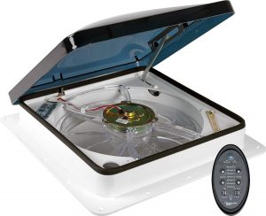
FAN-TASTIC VENT RV Vent 2250 User Guide

SAFETY INFORMATION
FOR YOUR SAFETY READ ALL INSTRUCTIONS BEFORE OPERATING FAN REFER TO MODEL STICKER UNDER POP N’ LOCK SCREEN FOR MODEL NUMBER
SAFETY ALERT SYMBOLS
Safety Symbols alerting you to potential personal safety hazards. Obey all safety messages following these symbols.
WARNING : avoid possible injury or death
CAUTION : avoid possible injury and/or property damage.
WARNING ELECTROCUTION
- Disconnect power supply prior to installation.
INSTALLATION
RECOMMENDED WIRE FOR POWER SUPPLY:
A minimum of 16-gauge stranded copper must be used. Insulated connectors must be used.
WIRE COLOR CODE: Black – Positive or Fused White – Negative or Ground.
ROOF MOUNTING INSTRUCTIONS: OEM (ORIGINAL EQUIPMENT MANUFACTURERS) & AFTERMARKET
Gasket or Sealer is required between mounting flange bottom & top of roof. Additional compatible sealant over screws & at flange where it meets roof. Clamp fans; use a double bead of compatible sealant only between the mounting flange and roof (No putty tape, buty l or gaskets to be used with Clamp Fans). For rubber roofs use EPDM compatible roof sealant, e.g. Dicor 551 LSW or 502 LSW.
RECOMMENDED SCREWS:
No. 8 self-tapping flat head – 3/4” to 1” in length. All 16 holes must be used for proper seal. After ceiling fan has been mounted and wired, install interior garnish wit screws provided. Garnish may be trimmed for thinner roofs. For deeper than standard garnish call Fan-Tastic Vent Toll Free. OEM Clamp fans require mounting screws and correct height garnish pre-determined by OEM Customer and Fan-Tastic Vent. Torque all screws equally. Do not over tighten.
FUSE: SYSTEM HAS BEEN FUSED BY FAN-TASTIC VENT. REPLACE ONLY WITH A 4 AMP SLO BLO TYPE FUSE. REPLACEMENT INSTRUCTIONS:
Locate the round black cap of the fuse holder (about the size of a dime) on the face of the fan. Push up and quarter turn counter clockwise and pull down to expose the fuse. Replace the old fuse with a new one and push in the fuse holder. Secure with clockwise rotation of the cap. REPLACEMENT MUST BE SAME TYPE AND RATING.
REVERSE SWITCH MOUNTED ON THE FAN:
Units equipped with a reverse switch in the fan motor and fan blade must be completely stopped before reversing fan.
BULB TYPE THERMOSTAT INSTRUCTIONS:
No additional external wiring.
NOTE:
A SAFETY SWITCH HAS BEEN INSTALLED ON THE UNIT, DOME MUST BE OPENED APPROXIMATELY 3 INCHES BEFORE MOTOR WILL OPERATE. WHEN DOME IS SHUT COMPLETELY, MOTOR WILL NOT OPERATE.
PERMANENT MAGNET MOTORS PERFORM AS DESIGNED ON FILTERED DC CURRENT. UNFILTERED DC CURRENT MAY CREATE IRRITATING NOISE FROM FAN BLADE MOTORS AND MAY CAUSE CIRCUIT BOARDS TO FAIL.
HOW TO USE YOUR FAN-TASTIC VENT®
Close all vents when using your Fan-Tastic Vent®. Slightly open windows on shaded side of coach afford the most comfortable ambient air, even on hot days. Remember, you direct the air flow by opening a window. Always try to position yourself between an open window and the fan for greatest airflow comfort.
Any installation or operating problems call Fan-Tastic Vent toll free immediately, (800) 521-0298
AUTOMATIC LIFT MOTORS
To manually open or close the lid on your Fan-Tastic Vent®, grasp the black hand knob and turn in the direction desired. DO NOT PULL DOWN ON THE KNOB! Doing so may damage your fan and/or cause physical injury.
Previous Fan-Tastic Vent® Models used a two position (clutch) knob that required pulling down to activate the manual feature. This new lift motor does not require any such action.
OPERATION
CAUTION POSSIBLE PROPERTY DAMAGE
DO NOT LEAVE VENT LID OPEN AND UNATTENDED FOR EXTENDED PERIODS OF TIME. HIGH WINDS OR OTHER UNUSUAL CONDITIONS MAY RESULT IN LEAKAGE AND/OR SERIOUS DAMAGE!
CAUTION POSSIBLE PROPERTY DAMAGE
Operator should use common sense when operating any vent and avoid use in inclement weather if adverse conditions threaten.
MANUAL LIFT FANS
- Open dome approximately 4” or more (ceiling fan has a built in safety switch that will not allow the fan motor to operate unless the dome is partially open).
- Turn 3-speed knob to desired performance level (0-Off, 1-Low, 2-Medium, 3-High).
- Open a window or door for air flow.
- Source of airflow is determined by the window(s) or door(s) opened. For best results, close all roof vents and open 1 (one) window the greatest distance from your Fan-Tastic Vent fan.
FAN EQUIPPED WITH REVERSE SWITCH MOUNTED ON THE FAN
- Turn fan motor off by : setting 3-speed switch to 0 – Off, closing the dome or selecting the center position on the In/Off/Out rocker switch.
- Wait for fan blade to stop.
- Select IN position, brings air from the roof area into your coach (pressurizes inside).
- Or select OUT position, to bring air in through any or all openings in coach and exhausts through the roof.
- Turn fan motor ON, select desired speed.
FAN EQUIPPED WITH THERMOSTAT MOUNTED ON THE FAN
- Follow operating instructions 1 through 4 above.
- Select desired temperature or comfort level on the thermostat. Fan motor will start and stop automatically as the interior temperature of the coach exceeds or drops below the selected temperature level.
MAINTENANCE
CAUTION
Use 12 Volt power only! Connecting you fan to 110 Volt power will damage the internal circuit board (if applicable) and/or the fan motor and render it inoperable and may cause property damage.
READ INSTRUCTIONS ENTIRELY BEFORE BEGINNING
REPLACING THE FUSE
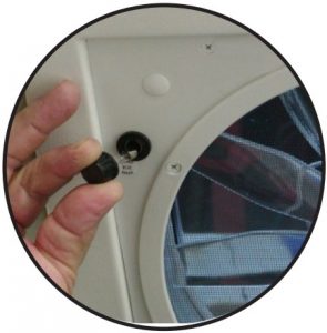
- Locate the black cap on the face of the screen assembly. Twist the cap in a counter-wise direction (from right to left) one quarter to one half turn and gently pull down on the cap. The cap should come free with the fuse attached to the backside(see Fig. 1).
- Inspect the fuse to see if the wire inside the glass is broken and replace if necessary. Be sure to use only a 4 amp Slo Blo Fuse.
- Put one end of the new fuse into the backside of the fuse holder cap and gently push the other end of the fuse all the way up inside the fuse holder.
- Screw the black fuse cap back into place by turning in a clockwise direction (left to right) until snug (1/4 to 1/2 turn) and release.

FIXING A STICKING LID
Occasionally the lid on your Fan-Tastic Vent may stick to the EPDM rubber seal. Warm temperatures cause the seal to dry out but it can easily be fixed. You will need Denatured or Rubbing Alcohol, Water based Protectant, or 100 % Silicone and a couple of clean rags.
- Open the dome (lid) all the way.
- Put a liberal amount of denatured or rubbing alcohol on a clean rag and clean the underside of the lid and the EPDM rubber seal.
- If available, apply a water (not petroleum) based protectant (i.e. 303 Protectant) to the inside of the dome where the dome and seal meet. Allow to dry and buff the lid with a soft cloth to a high sheen.
- Place *AK-1000 on a clean rag, paper towel or foam trim brush and apply an even coating to the entire top surface of the EPDM rubber dome seal.
- For easy clean up; Wipe all excess fluid off hands onto a rag or towel and wash thoroughly with soap and water. 6. Resume using your Fan-Tastic Vent as desired.
*We recommend AK-1000 (100% Silicone) and it is available through Fan-Tastic Vent upon request. AK-1000 is a non-hazardous material. MSDS available upon request.
Note: if the seal EPDM rubber dome seal is damaged or torn, contact Fan-Tastic Vent for replacement.
CLEANING INSTRUCTIONS
Note: In 2015 the fan blade was changed to a more efficient, smaller diameter fan blade that can be removed through the screen assembly. Older fans (built before 2015) with the larger diameter blade cannot do this and require dropping the entire screen assembly for removal.
- Open dome all the way. Remove the fuse by pushing up and turning the black fuse cap 1/4 turn counter-clockwise and pull down (Fig. 1).
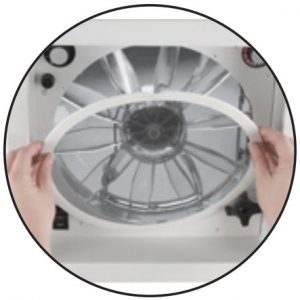
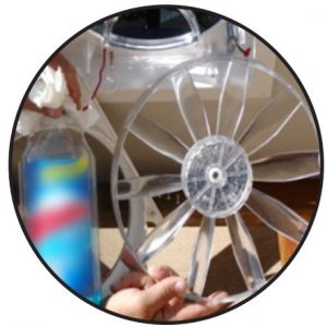
- Remove the Pop N’ Lock™ screen ring by grasping the finger tab with one hand and pull straight down. Use your free hand to brace against the screen assembly (aka Control Panel) (Fig. 2) to prevent breaking the Pop N’ Lock Screen. Removal of the Pop N’ Lock may be difficult at first but will get easier with repeated removal. To remove the fan blade for cleaning: For fans built prior to 2015 skip to Step
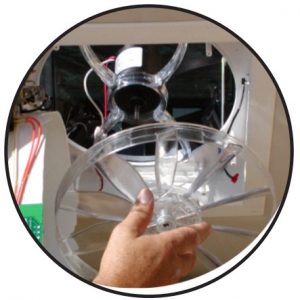
- For fans built after 2014 with a smaller diameter blade (current standard) : Use one hand to hold the fan blade to prevent it from turning and remove the Phillips head screw from the center hub face of the fan blade. With the fan blade screw removed, grasp the fan blade with two hands on opposite sides (i.e. 3 & 9 o”clock positions) and firmly pull down. It may be necessary to wiggle the fan blade up and down, side to side until it slides off the motor shaft (Fig. 3). and continue to Step 8.
- Remove two screws from the lift motor and unplug it from the quick connects (if your fan is manual, remove the center screw from the black lift knob).
- Remove the remaining screws from the face of the screen assembly (control panel) and gently guide the entire screen assembly down and let it hang by its’ internal wires.
- If fan is equipped with a rain sensor, locate the two 28 gauge black wires that feed down from the top side of the fan through the t-slot in the base. Trace the wires to the white connector on the circuit board and carefully unplug it. *You may unscrew the rain sensor strip (under the lid) from the top of the fan base and feed it through the t-slot (in the base) to be pulled inside, intact, later.
- With the screen assembly hanging down off to one side, use one hand to hold the fan blade to prevent it from turning and remove the Phillips head screw from the center hub face of the fan blade. With the fan blade screw removed, grab the fan blade with two hands on opposite sides (i.e. 3 & 9 o’clock postions) and firmly pull down. It may be necessary to wiggle the fan blade up and down, side to side until it slides off the motor shaft (Fig. 3).
- Clean the screen insert (Pop N’ Lock) and fan blade with window cleaner or non-abrasive dish soap and warm water (Fig. 4). ** The “Top Rack” of an automatic dishwasher may also be handy to clean the screen and fan blade.
- Re-assemble your fan by reversing the appropriate Steps 1 through 3 or Steps 1 through 7. and enjoy your Fan-Tastic Vent.
- **OPTION…Once the screen and blade are clean and dry, you may wipe or spray a water based protectant (do not use any petroleum based protectants) on the screen and blade and buff to high gloss. This minimizes dust and dirt build up and eases cleaning.
CAUTION
Do not operate fan without the Pop N’ Lock screen in place.
- Fig. 2
- Fig. 3
- Fig. 3


REMOTE CONTROL CARE AND MAINTENANCE BATTERY INSTALLATION
- Keep the remote dry. If it gets wet, wipe it dry immediately.
- Use and store the remote only in normal temperature environments
- Keep the remote away from dust and dirt.
- Wipe the remote only with a damp cloth occasionally to keep it looking good.
- Handle the remote carefully and avoid dropping it or rough handling.
BATTERY INSTALLATION
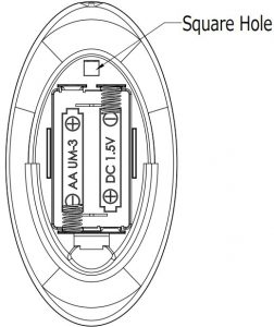
- The Model 7300/7350 Remote Control is powered by two AA batteries (included). Please be sure to match the (+) and (-) on the batteries to the (+) and (-) markings inside the battery compartment (Fig. 6).
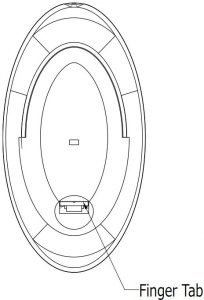
- To remove the battery compartment cover, located on the rear of the remote, pull back on the finger tab (Fig. 6) and lift up.
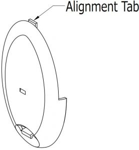
- To close the battery compartment cover, place the alignment tab (Fig. 8) located opposite the finger tab into the square hole (Fig. 7) on the back of the remote.Push the cover down until the finger tab “clicks” into place.
BATTERY PRECAUTIONS:
- Do not mix old and new batteries.
- Do not mix alkaline, standard (carbon-zinc), or rechargeable (nickel-cadmium) batteries.
- Remove batteries from the remote control before storing or long periods of non-use.
- Always remove old, weak, or worn-out batteries promptly and recycle or dispose of them in accordance with Local and National Regulations.
MODEL 7300/7350 INFRARED REMOTE CONTROL
- Fig. 6
- Fig. 7
- Fig. 8


CONTROLLER WALL MOUNT INSTALLATION
All of Fan-Tastic Vent’s external controls (wired and wireless) are capable of being mounted to a wall. The following applies to all wired controllers (excluding panel mounts).
- Locate the notch on the bottom edge of the controller (Fig. A).
- Place a small coin (penny, dime) or flat screwdriver into the notch and twist until the controller back plate pops loose.
- Separate the back plate from the controller.
- Pull the RJ 11 controller cable (in the wall) through the square hole in the back plate (from the backside to front) and plug it into the front half of the controller (Fig. B).
- Hold the back plate to desired wall location and secure with two recommended #8x 3/8” T/S Flat Head screws using the two round holes provided (1 top, 1 bottom) (Fig. C).
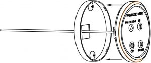
- Push the front half of the wall controller onto the back plate being sure to align the connector plug (Fig. D) with the square hole and snap together.
Fig. A
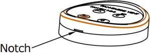
Fig. B
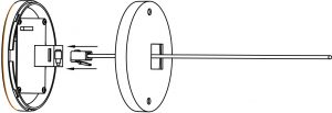
Fig. C
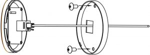
Fig. D


RAIN SENSOR EQUIPPED FANS
Conditions like a hot steamy shower, leaving the dome open with the fan blade motor off at dew point or operating the fan blade motor during a light to moderate rain shower may warrant turning off the system rain sensor (wall control models 5300,6300 & 7300 series) consult your fan models operation guide for instructions). When the dome (lid) is open and moisture contacts an active rain sensor, the lid closes and turns the fan blade motor off if it is running. Normal operation may be resumed by following normal start up procedures once the sensor is dry. When the rain sensor dries, the lid will not re-open automatically. Manual opening of the lid using the lift motor knob will bypass the rain sensor with the fan operation resumed to the setting prior to sensor activation. When the rain sensor has been overridden by manually opening the lid, the rain sensor will become active again once it has dried.
Operation Guide
MODEL 7350, 6350, 7300 & 6300 Premium Remote and Premium Wall Control
Fan On & Power Off
Press to :
- To Start fan (this will start the fan in Auto mode)
- To turn the fan off (this will stop the fan and close the lid)
Fan Speed
- (Pressing either button will change fan mode to Manual)
- Press to increase the fan speed
- Press to decrease the fan speed
These buttons only work in Manual mode. The fan has 13 speeds. Fan speed is indicated on the remote in % from 10% (Low Speed) to 100% (High speed). An LED will illuminate next to the % of fan speed. If two LED’s are illuminated, then the speed is half way between the illuminated %. (ex. Both 85% and 100% LED are illuminated; then the speed is approximately 93%).
Thermostat Temperature Setting-Fahrenheit/Celcius
- (Pressing either button will change fan mode to Auto)
- Press to increase the Set Temperature
- Press to decrease the Set Temperature
These buttons only work in Auto mode. The fan has 13 Temperature settings. Temperature Setting is indicated on the remote in Fahrenheit Degrees (60-90 Degrees F/15-30 Degrees C). An LED will illuminate next to the Degree setting of the thermostat. If two LED’s are illuminated, then the Thermostat setting is half way between the illuminated Degrees. (ex. Both 85F and 90F LED are illuminated; then the setting is approximately 88F)
Vent Lid Up/Down
Pressing this button will NOT change the fan mode. (The Rain Sensor can be turned on or off by holding this button down for 3 seconds)
When the vent lid is closed, press this button once to open the vent lid. When the vent lid is open, press this button once to close the lid. This will operate independent of fan on/off.
Air Out/In (models 7350 & 6350) (Pressing button will not change the fan mode)
In either Manual or Auto mode and the vent lid is open, press this button once to reverse the fan blade direction, press it again for the opposite direction.

Note: Remote and Fan control board must be in communication for the setting on the remote to change. The fan control acknowledges command inputs from the remote with an audible “beep”. If a single beep is not heard then the command was not received.
Rain Sensor off : This LED will illuminate when the rain sensor has been turned off. (The Rain Sensor can be turned on/off at the switch on the fan OR by holding down the Up/Down button for 3 seconds).
Manual :
- This LED will illuminate when the controls are in Manual mode.
- Press Speed up/down to enter Manual mode
Auto :
- This LED will illuminate when the controls are in Auto mode.
- Press Temp up/down to enter Auto mode
TO OPEN DOME WITHOUT RUNNING THE FAN
If motor is running, press fan off button, then press dome up/down to re-open the dome.
Note: A double beep indicated a command is not allowed.
Note: Wireless remote control models (7300 & 7350) only, will “sleep” or shut off 30 seconds after the last command to preserve battery life. To “awaken” the controller push any button on the controller and it will show the last temperature and/or speed setting received before “sleeping”. If the controller is manually shut off using the ON/OFF button, all settings are reset.
Fan On & Power Off
Press to :
- To Start fan (this will open the lid and start the fan on high)
- To turn the fan off (this will stop the fan and close the lid)
Fan Speed
- Press to increase the fan speed
- Press to decrease the fan speed
- The fan has 13 speeds. Not including ‘off’
Vent Lid Open / Close (model 5350)
(The Rain Sensor can be turned on or off by holding this button down for 3 seconds).
When the vent lid is closed, press this button once to open the vent lid.When the vent lid is open, press this button once to close the lid. This operates independent of Power On/Off.
Vent Lid Open (model 5300)
When the vent lid is closed, press this button once to open the vent lid.
Vent Lid Close (model 5300)
(The Rain Sensor can be turned on or off by holding this button down for 3 seconds) When the vent lid is open, press this button once to close the vent lid.
Air Out/In (model 5350)
When the vent lid is open, press this button once to reverse the fan blade direction, press it again for the opposite direction. Once pressed, the motor will slow and reverse. If pressed again during the reversing cycle, a double beep will indicate that the cycle is in process. The function can only be changed after the reversing cycle is complete.
Note: Slow beep and double beep – see notes on controller 7350 instructions.
Note: FOR WALL CONTROLLED FANS, When the fan is running, closing the lid using the up/ down button shuts the fan blade off. Re-opening the lid using the up/down button will resume fan blade to previous set speed. Using the On/Off button will not do this. The On/Off button resets fan to normal start.
Note: these are ‘hard wire’ RJ11 wall mounted controls

Model 5350
Rain Sensor Off
This LED will illuminate when the rain sensor has been turned off at the wall control. (The Rain Sensor can be turned on/off by holding down the Up/Down button for 3 seconds).

Model 5300
Rain Sensor Off
This LED will illuminate when the rain sensor has been turned off at the wall control. (The Rain Sensor can be turned on/off by holding down the Down button for 3 seconds) .
Fan On & Power Off
Press to :
- To Start fan (this will open the lid and start the fan on high)
- To turn the fan off (this will stop the fan and close the lid)
Fan Speed
- Press to increase the fan speed
- Press to decrease the fan speed
- The fan has 13 speeds. Not including ‘off’
Vent Lid Open / Close (model 5250)
- When the vent lid is closed, press this button once to open the vent lid.
- When the vent lid is open, press this button once to close the lid.
- This operates independent of Power On/Off.
Vent Lid Open (model 5200)
When the vent lid is closed, press this button once to open the vent lid.
Air Out/In (model 5250)
When the vent lid is open, press this button once to reverse the fan blade direction, press it again for the opposite direction.

Model 5250

Model 5200
Note: these are ‘hard wire’ RJ11 wall mounted controls
Fan On 1-2-3
Press to start the fan. Each press increases the fan speed one level.
- First press turns fan on and opens the dome at lowest level speed
- Second press changes fan to level 2 speed
- Third press changes fan to level 3 speed
- Fourth press returns fan to level 1 speed
Fan Power Off
Press to :
- To turn the fan off (this will stop the fan and close the lid)
Vent Lid Open
When the vent lid is closed, press this button once to open the vent lid. This operates independent of Power On/Off.
Vent Lid Close
When the vent lid is closed, press this button once to close the lid. This operates independent of Power On/Off.
Note: this is a ‘hard wire’ RJ11 wall mounted control.

Note: FOR WALL CONTROLLED FANS, When the fan is running, closing the lid using the up/down button shuts the fan blade off. Re-opening the lid using the up/down button will resume fan blade to previous set speed. Using the On/Off button will not do this. The On/Off button resets fan to normal start.
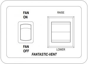
Operation Guide MODEL 4100/4150/4175 Formerly B-Series (B2000/B8100, B2000/B8100R, B2000/B8100RBT)
- Activate your fan by pre-selecting 1-low, 2-medium or 3-high, on fan blade speed switch.
- On wall control press RAISE/LOWER switch pad. Select “RAISE” position and hold until dome (lid) reaches desired height and release. At full open when the dome lift motor stalls, immediately release the switch pad. Select “Lower” position and hold until lid lowers to desired height and release. At fully closed when the dome lift motor stalls, release switch pad immediately!*
*NOTE; continuing to hold pad after dome is open or closed will cause damage to the lift system. - When the fan is equipped with a fan blade motor reversing switch, pre-select either “OUT” or “IN” on the switch**, the center position is “OFF”. As dome opens and reaches approximately 2” the fan blade turns on to pre-selected speed and direction. When the lid closes, the fan motor automatically turns off. Anytime you reverse the fan blade motor while the system is in operation, select center OFF (neutral) position and allow the fan blade to stop completely. Once stopped, select the opposite direction to restart the motor.
**Note; “Out” or exhaust mode, pulls clean fresh air in through a slightly open window while expelling hot, stale, stuffy air out to the roof area. “IN” or intake mode, draws air into the coach from the roof area and effectively pressurizes the coach if all windows, doors and other vents are closed. - When the fan is equipped with a built-in thermostat, pre-select a comfort setting from deep blue to deep red on thermostat dial (22º to 123º Fahrenheit). The fan motor will turn on and off based on the interior ambient temperature versus thermostat setting. When the thermostat temperature is “satisfied”, the fan motor will turn off and the lid stays open. When the thermostat calls for cooling, the fan blade motor turns on automatically. Remember, the lid must be open at least 2” and OUT or IN must be selected (not the center OFF position) and the ON/OFF switch on the wall controller next to the RAISE/LOWER switch must be in the “ON” position before the thermostat can turn the fan blade on.
Model 4100 (Standard)

Operation Guide MODEL 3300/3350 Formerly (6000BT/6000RBTA)
- Turn 3-speed knob to desired performance level (0-Off, 1-Low, 2-Medium or 3-High). This activates the fan.
- Select UP to raise the dome (lid) or Down to close the lid from the mini-rocker switch located near the Lift Motor.
- When equipped with a Fan Blade On/Off Switch (Model 3300) select ON or OFF. When a fan is equipped with a fan blade motor reversing switch (Model 3350), pre-select either “OUT”, “IN” or the center “OFF” position on the switch**. As dome opens and reaches approximately 2” the fan blade turns on to pre-selected speed and direction. When the lid closes, the fan motor automatically turns off. Anytime you reverse the fan blade motor while the system is in operation, select center OFF(neutral) position and allow the fan blade to stop completely. Once stopped, you may safely select the opposite direction to restart the motor.
**Note; “Out” or exhaust mode, pulls clean fresh air in through a slightly open window while expelling hot, stale, stuffy air out to the roof area. “IN” or intake mode, draws air into the coach from the roof area and effectively pressurizes the coach if all windows, doors and other vents are closed. - These two models are equipped with a built-in thermostat. Pre-select a comfort setting from deep blue to deep red on thermostat dial (22º to 123º Fahrenheit). The fan motor will turn on and off based on the interior ambient temperature versus thermostat setting. When the thermostat temperature is “satisfied”, the fan motor will turn off and the lid stays open. When the thermostat calls for cooling, the fan blade motor turns on automatically. Remember, the lid must be open at least 2” and OUT or IN must be selected and not the center OFF position (Model 3350) or the ON/OFF switch on the fan must be in the “ON” position (Model 3300)before the thermostat can turn the fan blade on.
- Both models are also equipped with a Rain Sensor. When the lid is open and moisture contacts the sensor, the lid closes and turns off the fan blade motor if it was running. When the rain sensor dries, it will not re-open the lid automatically. Manual opening of the lid using the lift motor knob will bypass the rain sensor with fan operation resumed to setting prior to sensor activation. When the rain sensor has been overridden by manually opening the lid, the rain sensor will become active again once it has dried.
Operation Guide MODEL 4201/4251/4301/4351
- Turn 3-speed knob to desired performance level (0-Off, 1-Low, 2-Medium or 3-High). This activates the fan.
- Select UP to raise the dome (lid) or Down to close the lid from remote mounted wall switch.
- When equipped with a Fan Blade On/Off Switch (Model 4201/4301) select ON or OFF. When a fan is equipped with a fan blade motor reversing switch (Model 4251/4351), pre-select either “OUT”, “IN” or the center “OFF” position on the switch**. As dome opens and reaches approximately 2” the fan blade turns on to pre-selected speed and direction. When the lid closes, the fan motor automatically turns off. Anytime you reverse the fan blade motor while the system is in operation, select center OFF (neutral) position and allow the fan blade to stop completely. Once stopped, you may safely select the opposite direction to restart the motor.
**Note; “Out” or exhaust mode, pulls clean fresh air in through a slightly open window while expelling hot, stale, stuffy air out to the roof area. “IN” or intake mode, draws air into the coach from the roof area and effectively pressurizes the coach if all windows, doors and other vents are closed. - Both models 4301 & 4351 are also equipped with a Rain Sensor. When the lid is open and moisture contacts the sensor, the lid closes and turns off the fan blade motor if it was running. When the rain sensor dries, it will not re-open the lid automatically. Manual opening of the lid using the lift motor knob will bypass the rain sensor with fan operation resumed to setting prior to sensor activation. When the rain sensor has been overridden by manually opening the lid, the rain sensor will become active again once it has dried.
FAN-TASTIC VENT PRODUCT WARRANTY
The Following Guidelines Apply To All Work Done on our Fan-Tastic Vent Products
Effective January 1, 2013 : Parts and Labor – 2 Years – Fans only Additional part only warranty – another 5 years. but freight charges could apply.
Lifetime on Dome, but after 4 years then freight charges would apply.
THIS WARRANTY IS EXPRESSLY IN LIEU OF ANY OTHER EXPRESS OR IMPLIED WARRANTY, INCLUDING ANY IMPLIED WARRANTY TO MERCHANTABILITY OR FITNESS FOR ANY PURPOSE. UNDER NO CIRCUMSTANCE IS FTV LIABLE FOR INDIRECT, SPECIAL, INCIDENTAL OR CONSEQUENTIAL DAMAGES.
This WARRANTY does not cover any product which may have been damaged in transit or installation or has been subject to misuse, neglect or has been used in violation of FTV’s instructions.
THERE ARE NO OTHER WARRANTIES THAN THOSE EXPRESSLY STATED HEREIN.
PRODUCT REGISTRATION FORM
Please visit www.fantasticvent.com to register your product.
Product Overview
