FLYSKY FS-MG41 Digital Proportional Radio Control System User Manual
Thank you for purchasing our product, an ideal radio system for beginners or experienced users.
In order to ensure your safety, and the safety of others, read this manual carefully before using this product. If you encounter any problem during use, refer to this manual first. If the problem persists, contact your local dealer or visit our service and support website : www.flysky-cn.com
Safety
Pay close attention to the following symbols and their meanings. Failure to follow these warnings could cause damage, injury or death.
Danger
Not following these instructions may lead to serious injuries or death.
Warning
Not following these instructions may lead to major injuries.
Attention
Not following these instructions may lead to minor injuries.
Safety Guide
Prohibited Mandatory
- Do not use the product at night or in bad weather like rain or thunderstorm. It can cause erratic operation or loss of control.
- Do not use the product when visibility is limited.
- Do not use the product on rain or snow days. Any exposure to moisture (water or snow) may cause erratic operation or loss of control.
- Interference may cause loss of control. To ensure the safety of you and others, do not operate in the following places:
- Near any site where other radio control activity may occur
- Near power lines or communication broadcasting antennas
- Near people or roads
- On any body of water when passenger boats are present
- Do not use this product when you are tired, uncomfortable, or under the influence of alcohol or drugs. Doing so may cause serious injury to yourself or others.
- The 2.4GHz radio band is limited to line of sight. Always keep your model in sight as a large object can block the RF signal and lead to loss of control.
- Do not touch any part of the model that may generate heat during operation, or immediately after use. The engine, motor or speed control, may be very hot and can cause serious burns.
- Misuse of this product may lead to serious injury or death. To ensure the safety of you and your equipment, read this manual and follow the instructions.
- Make sure the product is properly installed in your model. Failure to do so may result in serious injury.
- Make sure to disconnect the receiver battery before turning off the transmitter. Failure to do so may lead to unintended operation and cause an accident.
- Ensure that all motors operate in the correct direction. If not, adjust the direction first.
- Make sure the model stays within the systems maximum range to prevent loss of control.
Introduction
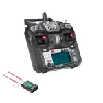
The FS-MG41 is a simplifed 4-channel transmitter that adopts the 2.4GHz ANT Automatic Frequency Hopping Digital System . The transmitter is lightweight and compact in design, comfortable and ergonomic. It has a beginner mode and is easy for beginner players to use.
Transmitter Overview
| [1] | Traversing handwheel, 35 degrees on each side(CH1) |
[10] | ST.D/R |
| [2] | Throttle button, 25 degrees in front and 12.5 degrees at rear(CH2) |
[11] | TH.D/R |
| [3] | Push button switch (CH4) [Push button function is flip type] |
[12] | Switch to the electric adjustment mode |
| [4] | Three-position toggle switch(CH3) | [13] | TH.REV |
| [5] | Lanyard hole | [14] | G.LED |
| [6] | Handle, 4*AAA battery compartment | [15] | BIND |
| [7] | ST.REV | [16] | ST.TRIM |
| [8] | R.LED | [17] | TH.TRIM |
| [9] | RX.BATT | [18] | Power Switch |
Receiver Overview (Take FS-R4A as an example)
| [1] | CH1 | [12] | Antenna |
| [2] | CH3 | [13] | LED |
| [3] | CH4 | [14] | Battery line“-” |
| [4] | Left Light port | [15] | Battery line“+” |
| [5] | Right Light port | [16] | Motor line“M-” |
| [6] | Head Light port | [17] | Motor line “M+” |
| [7] | Tail Light port | [18] | Power switch line |
| [8] | Ambient Light port | [19] | Stickers |
| [9] | Roof Light port | [20] | Channel port “S ” |
| [10] | Light port“-” | [21] | Channel port“+” |
| [11] | Light port“+” | [22] | Channel port“-” |
Getting Started
Before operation, install the battery and connect the system as instructed below.
Transmitter Battery Installation
Danger
- Only use specified battery (X4 AA batteries).
- Do not open, disassemble, or attempt to repair the battery.
- Do not crush/puncture the battery, or short the external contacts.
- Do not expose to excessive heat or liquids.
- Do not drop the battery or expose to strong shocks or vibrations.
- Always store the battery in a cool, dry place.
- Do not use the battery if damaged.
Battery Type: AAA
Battery Installation:
- Open the battery compartment cover.
- Insert 4 fully-charged AAA batteries into the compartment. Make sure that the battery makes good contact with the battery compartment’s contacts.
- Replace battery compartment cover.
Low battery alarm: When the battery is lower than 4.2v, the G.LED on the panel will flash slowly.
Note: When installing the batteries, be careful to handle the positive and negative poles. (As shown in the picture on the right)
Instructions
After setting up, follow the instructions below to operate the system.
Power On
Follow the steps below to turn on the transmitter:
- Check to make sure that that battery is fully charged and installed correctly.
- Toggle the switch to the [ON] position. When active the R.LED will be lit.
- Connect the receiver to power.
For safety always power on the transmitter before the receiver.
Note
- Operate with caution in order to avoid damage or injury.
- Make sure that the throttle is at its lowest position and the switches are set to their up position.
LED Indicator
- R.LED: The red power indicator;
- G.LED: The green status indicator;
- Car battery: Two colors light for battery volume display (hereinafter referred to as D3)
- When the power is high, the D3 green keeps on
- When the power is medium, the D3 yellow keeps on
- When the power is low, the D3 red keeps on
- When the power is off, the D3 red slow flash
- When the receiver drops the code, the two-colors light is off
Binding
The transmitter and receiver have already been bound at the factory.
However if the receiver needs to be replaced or additional receivers bound follow these steps:
- Turn on the transmitter while holding the bind button to enter bind mode. G.LED will start flashing quickly.
- Once in bind mode release the bind button.
- The receiver will power on and wait for 1 second ,if without connection, it will enter the matching code automatically;
- Once binding is successful the receiver’s LED will keep on.
Note: When binding, put the transmitter into bind mode first, then the receiver.
- applicable to the FS-MG4 transmitter and the FS-R4A receiver. Different receivers have different bind procedures. For more information visit the FLYSKY website for manuals and other related information.
- Product information is updated regularly, please visit our website for more information.
Stick Calibration
This function is used to set the neutral position for throttle and wheel.
Every transmitter is calibrated before leaving the factory, however if recalibration is required, please follow these steps:
- Turn and hold the wheel as far clockwise as it will turn, hold the throttle all the way forward, then turn on the transmitter in calibration mode.
- The R.LED and G.LED will flash twice.
- Car Battery the D3 yellow keeps on
- Calibrate wheel: Turn the wheel completely clockwise, then completely counterclockwise.
- When calibration is completed the R.LED will be off.
- Car Battery the D3 red keeps on
- Trigger calibration: Pull the trigger back then forward as far as it will go.
- When calibration is completed the G.LED will be off.
- Car Battery the D3 Green keeps on
- Both Wheel and rigger are Calibration passed
- the two-colors light is off
- Once calibration is complete press the bind key to save and exit.
Power Off
Follow the steps below to turn off the system:
- Disconnect the receiver power.
- Toggle the transmitter’s power switch to the off position.
Danger
Make sure to disconnect the receiver power before turning off the transmitter. Failure to do so may lead to damage or serious injury.
System Functions
This section focuses on the functions and how to use them.
Channel Description
The transmitter outputs a total of 4 channels, which are allocated as follows:
- CH1:Steering Wheel
- CH2:Throttle Trigger
- CH3:Three-position Switch
- CH4:Key Switch
Note: By default the output of CH4 is 1000us, after which pressing the button will toggle between 1000 and 2000us.
Channel Reverse
This function is used to adjust the action direction of the servo or motor The ST.REV / TH.REV switches are the reverse buttons for CH1 and CH2. If the switch is up it indicates reverse, and the down indicates normal.
Trims
The ST.TRIM is the trims for CH1 (steering ),and can be multiplexed as Trims of CH3 ;
The TH.TRIM is the trims for CH2(throttle).and can be multiplexed as Trims of CH4 ;
For multiplexing switching mode, see [5.5 Mode Switching].
Adjustment range: -120us- + 120us;
ST.TRIM/TH.TRIM: counterclockwise adjustment to increase the trim value. The maximum value is 120 us.
ST.TRIM- / TH.TRIM-: clockwise adjustment to decrease the trim value. The minimum value is -120 us.
D/R
The ST.D/R is the trims for CH1 (steering ),and can be multiplexed as Trims of CH3 ;
The ST.D/R is the trims for CH2(throttle).and can be multiplexed as Trims of CH4 ;
For multiplexing switching mode, see [5.5 Mode Switching].
Adjustment range: 0-120%;
ST.D/R: counterclockwise adjustment to increase the ser vo amount . The maximum value is
120%.
ST.D/R: clockwise adjustment to decrease the ser vo amount . The minimum value is 0%.
TH.D/R: counterclockwise adjustment to increase the servo amount. The maximum value is 120%.
TH.D/R: clockwise adjustment to decrease the servo amount. The minimum value is 0%.
Mode switching
This function is for reusing the ST.TRIM and ST.D / R buttons for different channels (see [5.3 Trims], [5.4 D/R).
Function setting:
Under normal power-on condition, press the BIND button twice (within 1S) to switch between mode 1 and mode 2. By default, mode 1 is used.
Mode 1: R.LED is always on. G.LED is off. ST.TRIM is for CH1 trim. ST.D/R is for CH1 servo adjustment . TH.TRIM is for CH2 throttle trim. TH.D/R is for CH2 throttle servo adjustment .
Mode 2: R.LED and G.LED are flashing alternately. ST.TRIM is for CH3 trim. ST.D/R is for CH3 servo adjustment . TH.TRIM is for CH4 trim. TH.D/R is for CH4 servo adjustment .
Failsafe
This function dictates what the receiver will do in the event that it loses signal from the transmitter, this includes servo position etc.
Setup:
When the transmitter is switched on in normal communication state, keep the channel to be set at the position of the failsafe setup, and press and hold the BIND button for 3S. The G.LED flashes for 2S, indicating that the setting is successful. That is, when the receiver cannot receive the signal, it will output the set failsafe value.
Note: The fail-safe function has no default set at the factory and as such must be set manually. If no failsafe setting has been set, then the receiver will not output anything when signal is lost.
Beginner Mode
Beginner mode is designed for people new to the hobby.
In this mode the throttle will be limited to 50 percent, The channel range defaults to 1250~1500~1750us.
Setup:
To switch between beginner and normal modes press and hold the channel 4 button as the transmitter is turned on.
Note: By default, the system is set to normal mode. The GLED will flash slowly for 3 seconds during power on if the system is set to beginner mode.
ESC Parameter Setting
The Dial Switch on the transmitter is used to set ESC parameters, that is, the Dial Switch is located at different positions and the corresponding parameter values are different.
Setting Method:
There are three parameters can be set for the ESC, which are “Running mode”, “Battery type”, “Drag brake”, There are slide switches numbered 1 2 3 4 on the radio panel . The above parameters can be set by dialing down and up. The specific operation is as follows:
When No. 1 slide switch is on the down, it indicates that the operation mode is set to FWD / REV / BRK.
When No. 1 slide switch is on the up, it indicates that the operation mode is set to FWD/REV.
When No. 2 slide switch is on the down, it indicates that the battery type is set to Lipo.
When No. 2 slide switch is on the up, it indicates that the battery type is set to NiMH.
When No. 3 and No.4 slide switch are on the down, it indicates that the drag brake force is set
to 0%.
When No. 3 slide switch is on the down and No.4 slide switch is on the up, it indicates that the drag brake force is set to 50%.
When No. 3 slide switch is on the up and No.4 slide switch is on the down, it indicates that the drag brake force is set to 75%.
When No. 3 and No.4 slide switch are on the up, it indicates that the drag brake force is set to 100%.
Parameter Explanation:
- Running Mode
FWD/REV/BRK: This mode adopts “double click” reverse mode, that is, when the throttle trigger is pushed from netural range to the reverse area for the first time, the motor is only braking and will not reverse; when the throttle trigger is moved back to the netural range and pushed to the reverse area for the second time, it will reverse. This mode is applicable to general models.
FWD/REV: This mode adopts “one click” reverse mode, that is, when the throttle trigger is pushed from netural range to the reverse area, the motor immediately generates reverse action, which is generally applied to rock crawler. Parameter setting method:
When No. 1 slide switch is on the down, it indicates that the operation mode is set to FWD / REV / BRK.
When No. 1 slide switch is on the up, it indicates that the operation mode is set to FWD/REV. - Battery Type
There are LiPo and NiMH cells. The low-pressure protection value is different under different types. It can be set according to the actual use.
Parameter setting method:
When No. 2 slide switch is on the down, it indicates that the battery type is set to Lipo.
When No. 2 slide switch is on the up, it indicates that the battery type is set to NiMH. - Drag Brake Force
The drag brake means that when the throttle trigger moves from the forward or reverse area to netural range, it will produce certain braking force to the motor, the larger the value is, the greater the drag brake force is. Select proper braking force according to the actual situation.
Parameter setting method:
When No. 3 and No.4 slide switch are on the down, it indicates that the drag brake force is set to 0%.
When No. 3 slide switch is on the down and No.4 slide switch is on the up, it indicates that the drag brake force is set to 50%.
When No. 3 slide switch is on the up and No.4 slide switch is on the down, it indicates that the drag brake force is set to 75%.
When No. 3 and No.4 slide switch are on the up, it indicates that the drag brake force is set to 100%.
Product Specifications
This section contains FS-HW-MG41 transmitter and HW709 receiver specifications.
Transmitter Specification( FS-MG41)
| Product Model | FS-MG41 |
| Channels | 4 |
| Model Type | Car, Boat |
| RF | 2.4GHz ISM |
| RF Power | <20dBm |
| 2.4GHz Protocol | ANT |
| Distance | >150m(ground) |
| Channel Resolution | 1024 |
| Battery | 6V DC 1.5AAA*4 |
| Charging Interface | NO |
| Life time | According to battery type |
| Low Voltage Warning | <4.2V |
| Antenna Type | Built-in single antenna |
| Data Interface | No |
| Temperature Range | -10℃—+60℃ |
| Humidity Range | 20—95% |
| Online Update | No |
| Color | Black |
| size | 118*73*145mm |
| weight | 1300g |
| Certification | CE,FCC ID:N4ZMG400 |
Receiver Specification
FS-R4A:
| Product Model | FS-R4A |
| Main applications LiPo/NiMH Cells |
1/16、1/18 On- road, Buggy, SCT, Truck and Rock Crawler 2 LiPos or 5-7 NiMH cells |
| Continuous / peak current | 10A / 50A |
| Parameter setting | Radio |
| Channels | 4 |
| RF | 2.4GHz ISM |
| 2.4GHz Protocol | ANT |
| RF Power | <20dBm |
| Distance | >150m(ground) |
| Antenna Type | single antenna |
| RSSI | No |
| Data Interface | PWM |
| Temperature Range | -10℃—+60℃ |
| Humidity Range | 20—95% |
| Online Update | No |
| weight | 13g |
| size | 33*29*14mm |
| Certification | CE, FCC ID :N4ZR4A00 |
HW-709:
| Product Model | HW-709 |
| Applicable motor
Main applications |
280/370 brushed motor ≥ 12T or RPM < 30000 @7.4V
1/16、1/18 On- road, Buggy, SCT, Truck and Rock Crawler |
| LiPo/NiMH Cells | 2 LiPos or 5-7 NiMH cells |
| Continuous / peak current | 25A / 120A |
| Parameter setting | Radio |
| PWM Channels | 2 |
| RF | 2.4GHz |
| 2.4GHz Protocol | ANT |
| RF Power | <20dBm |
| Distance | >300m(ground) |
| Antenna Type | Built-in single antenna |
| RSSI | No |
| Data Interface | PWM |
| Temperature Range | -10℃—+60℃ |
| Humidity Range | 20—95% |
| Online Update | No |
| weight | 23.9g(with 3.5mm bullet female connector) |
| size | 22.1g(with small TAMIYA male connector) 34*25*15.5mm |
| Certification | CE, FCC ID :N4ZHW-709 |
HW-711:
| Product Model | HW-711 |
| Applicable motor
Main applications |
280/370 brushed motor ≥ 12T or RPM < 30000 @7.4V
1/16、1/18 On- road, Buggy, SCT, Truck and Rock Crawler |
| LiPo/NiMH Cells | 2 LiPos or 5-7 NiMH cells |
| Continuous / peak current | 25A / 120A |
| Parameter setting | Radio |
| Channels | 4 |
| RF | 2.4GHz |
| 2.4GHz Protocol | ANT |
| RF Power | <20dBm |
| Distance | >300m(ground) |
| Antenna Type | Built-in single antenna |
| RSSI | No |
| Data Interface | PWM |
| Temperature Range | -10℃—+60℃ |
| Humidity Range | 20—95% |
| Online Update | No |
| weight | 23.9g(with 3.5mm bullet female connector) |
| size | 22.1g(with small TAMIYA male connector) 34*25*15.5mm |
| Certification | CE, FCC ID :N4ZHW-709 |
Package Contents
Transmitter*1(FS-MG41)
Receiver*1(FS-R4A)
Certification
DoC Declaration
Hereby, [Flysky Technology co., ltd] declares that the Radio Equipment [FS-MG41] is in compliance with RED 2014/53/EU.
The full text of the EU DoC is available at the following internet address: www.flysky-cn.com.
CE Warning
The antenna(s) used for this transmitter must be installed to provide a separation distance of at least 20 cm from all persons and must not be co-located or operating in conjunction with any other transmitter. End-users and installers must be provided with antenna installation instructions and transmitter operating conditions for satisfying RF exposure compliance.
Appendix 1 FCC Statement
This equipment has been tested and found to comply with the limits for a Class B digital device pursuant to part 15 of the FCC rules. These limits are designed to provide reasonable protection against harmful interference in a residential installation. This equipment generates, uses and can radiate radio frequency energy and, if not installed and used in accordance with the instructions, may cause harmful interference to radio communications. However, there is no guarantee that interference will not occur in a particular installation. If this equipment does cause harmful interference to radio or televison reception, which can be determined by turning the equipment off and on, the user is encouraged to try to correct the interference by one or more of the following measures:
- Reorient or relocate the receiving antenna.
- Increase the separation between the equipment and receiver.
- Connect the equipment into an outlet on a circuit different from that to which the receiver is connected.
- Consult the dealer or an experienced radio/TV technician for help.
To assure continued compliance, any changes or modifications not expressly approved by the party responsible for compliance could void the user’s authority to operate this equipment.
This equipment complies with Part 15 of the FCC Rules. Operation is subject to the following two conditions:
(1) This device may not cause harmful interference.
(2) This device must accept any interference received, including interference that may cause undesired operation.
Caution
The manufacturer is not responsible for any radio or TV interference caused by unauthorized modifications to this equipment. Such modifications could void the user authority to operate the equipment.
- The antenna(s) used for this transmitter must be installed to provide a separation distance of at least 20 cm from all persons and must not be co-lacated or operating in conjunction with any other transmitter. End-users and installers must be provided with antenna installation instructions and transmitter operating conditions for satisfying RF exposure compliance.
- Move all your channels to the desired position.
- Select [All channels] and then [Yes] in the confirmation box.
Environmentally friendly disposal
Old electrical appliances must not be disposed of together with the residual waste, but have to be disposed of separately. The disposal at the communal collecting point via private persons is for free. The owner of old appliances is responsible to bring the appliances to these collecting points or to similar collection points. With this little personal effort, you contribute to recycle valuable raw materials and the treatment of toxic substances.
CAUTION
RISK OF EXPLOSION IF BATTERY IS REPLACED BY AN INCORRECT TYPE.
DISPOSE OF USED BATTERIES ACCORDING TO THE INSTRUCTIONS
www.flysky-cn.com
Copyright ©2021Flysky Technology co., ltd
Release date: 2021-04-17
FCC ID:N4ZMG400
FCC ID:N4ZR4A00
