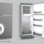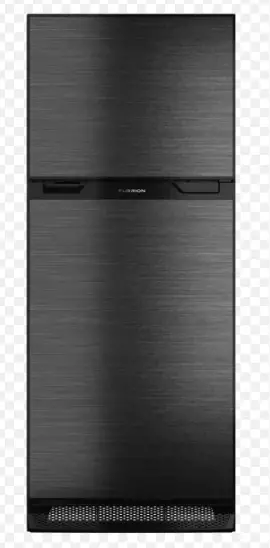
FURRION ARCTIC Built-In Refrigerator

IMPORTANT
- Thank you for purchasing this Furrion® product. Before operating your new appliance, please read these instructions carefully.
- This instruction manual contains information for safe use, installation and maintenance of the appliance.
- Please keep this instruction manual in a safe place for future reference. This will ensure safe use and reduce the risk of injury.
- Be sure to pass on this manual to new owners of this appliance.
- The manufacturer does not accept responsibility for any damages due to disregarding these instructions.
Important Safety Instructions
General Safety Warnings
CAUTION:
Improper installation, adjustment, alteration, service or maintenance can cause personal injury or property damage. For assistance or additional information, contact Furrion customer service.
- Do not allow anything to touch the refrigerator cooling system.
- Make sure the electrical installation follows all applicable code.
- Do not bypass or change the refrigerator’s electrical components or features.
- Do not spray liquids near electrical outlets, connections, or the refrigerator components. Most liquids are conductive, which can cause electric shock, short circuit or fire.
- The refrigerator cooling system is under pressure. Do not try to repair or to recharge a defective cooling system
- The shelves have been fixed according to safety regulation. The shelves must always be retained during operation and transportation. Contact Furrion customer service if the fixing mechanism is ever compromised.
- The rear of the refrigerator has sharp edges and corners. To prevent cuts or abrasions when working on the refrigerator, use caution and wear personal protection such as cut resistant gloves, and arm protection.
- Do not store or use gasoline or any flammable vapors and liquids in the vicinity of this refrigerator.
- This appliance is not intended for use by persons (including children) with reduced physical, sensory or mental capabilities, or lack of experience and knowledge, unless they have been given supervision or instruction concerning use of the appliance by a person responsible for their safety.
- Children should be supervised to ensure that they do not play with the appliance.
- To avoid an electrical shock hazard, relevant actions should be performed by qualified and certified professionals. Power should always be disconnected.
Proper Disposal of the Refrigerator
Risk of child entrapment. To avoid the possibility of child entrapment, please take the following precautions before you dispose of your refrigerator.
- Remove all doors.
- Leave shelves in place so children may not easily climb inside.
- Never allow children to play with, operate, or crawl inside the refrigerator.
Child entrapment and suffocation are not problems of the past. Junked or abandoned refrigerators are still dangerous even if they will sit for “just a few days.” If you are getting rid of your old refrigerator, please follow the instructions below to help prevent accidents.
Before you throw away your old refrigerator or freezer:
- Take off the doors.
- Leave the shelves in place so that children may not easily climb inside.
Refrigerants
All refrigeration products contain refrigerants, which under federal law must be removed prior to product disposal. If you are getting rid of an old refrigeration product, check with the company handling the disposal about what to do.
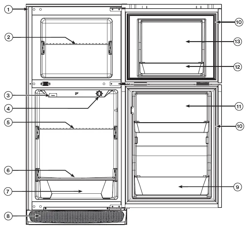
Parts and Features
| Item | Part Name |
| 1 | Trim Kit |
| 2 | Freezer Wire Shelf |
| 3 | Charcoal Filter |
| 4 | Temperature Control |
| 5 | Refrigerator Wire Shelf |
| 6 | Refrigerator Glass Shelf |
| 7 | Drawer |
| 8 | Air Vent |
| 9 | ½ Gallon Door Bin |
| 10 | Gasket |
| 11 | Refrigerator Door |
| 12 | Common Door Bin |
| 13 | Freezer Door |
Installation
All Furrion product referenced in this manual is to be installed in accordance with local and national codes, including the latest editions of the following standards:
USA:
− NFPA 1192
− NFPA 70
Canada:
− C22.1
− CSA Z240
What’s in the Box
- Set the unit upright.
NOTE: The refrigerator may have been laid on its back for transportation and delivery. This is acceptable, but must be stood up-right vertically for at least 4 hours before running the compressor to settle the compressor oil. - Unpack the unit, discard the packaging material appropriately.
- Confirm everything is in the box. If anything is damaged or missing, contact your dealer.
- Refrigerator x 1
- Instruction Manual x 1
- Warranty Leaflet x 1
- Refrigerator Door Lock Cover x 1
- Storage Lock x 1
Site Preparation
WARNING: FIRE OR EXPLOSION
Gas leaks may occur in your system and result in a dangerous situation. Always perform a leak test for possible leaks according to the manufacturer’s instructions after removing any appliance.
- Never leak test when smoking. Never use a flame.
- Do not use any appliance until connection has been leak tested and does not leak
- Remove the existing refrigerator (if applicable):
- Unplug the 120V AC power cord from the receptacle at the rear of the refrigerator enclosure.
- Disconnect the 12V DC leads from the refrigerator and cap the lead ends.
- Turn off the LP gas supply to the refrigerator.
- Disconnect the LP gas line from the refrigerator. Cap the line and verify there are no LP gas leaks.
- Remove the screws anchoring the refrigerator to the enclosure.
- Slide the refrigerator out from the enclosure and remove it from the RV.
Select Location
- Your new refrigerator must stand on a flat surface which should support a weight of 330Lbs (150kg). Surface must be level relative to the coach floor plane.
NOTE: A slope that is comfortable to live with, and from normal transportation is acceptable. - If the appliance is to be placed onto the carpet, support it with a wooden board. Do not place the appliance directly on the carpet, as the heat from the compressor may cause the carpet to fade.
- For best and most efficient operation, the refrigerator should operate within 50°F ~ 126°F (10°C ~ 52°C). If installing near large heat sources, such as furnaces, fireplaces, furnaces, etc. Ensure a thermal barrier, such as wood paneling isolates the refrigerator space as not to hinder performance of the appliance.
Refrigerator Cabinet/Enclosure Preparation
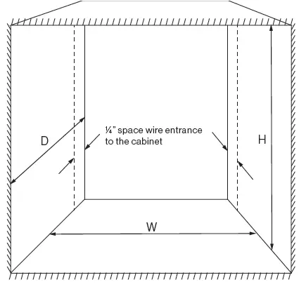
- The built-in refrigerator is designed for 0″ clearance to the sides, top. There is an intentional ¼” clearance between the back of the unit and cabinet to allow the service wire to enter the cabinet space. Frame the cabinet to the dimensions indicated below:
Model W H D FCR8DCDTA-* 23½”±1/8″ 527/8″±1/8″ 24″±1/8″ FCR10DCDTA-* 23½”±1/8″ 597/8″±1/8″ 24″±1/8″ - Squareness of the cabinet/enclosure needs to be within the “W” & “H” dimensions described in two places on either end. The diagonal measurement should be within ⅜” from each other.
- The base support of the cabinet/enclosure must be prepared with a 0 degree slope. If the existing cabinet/enclosure has a base with a slope, shimming is required to level and support the refrigerator.
NOTE: Cabinet/enclosures of absorption style fridges may be built with a 3 degree slope towards the rear. The slope is to allow moisture drainage towards the sidewall vent. - The cooling system is a forced air closed loop design, with inlet and exhaust on the bottom front of the unit. The enclosure does not need to be ventilated for any purpose. There is also no need for additional insulation on sides and top of the enclosure. The enclosure can be treated as a normal cabinet enclosure of the living space
- Face surfaces of the cabinet enclosure made from solid MDF should contain a softwood backing as a skeleton for mounting support, and to reduce splitting.
NOTE: A softwood core with MDF laminate, or a soft/hardwood face will be sufficient without a skeleton backing.
Electrical Preparation
Warning:
- Proper grounding is required for your safety, to prevent electrical shock or fire. The refrigerator is provided with the proper grounding for internal electric faults from the factory. This grounding must not be removed or altered.
- Ensure that the converter or DC power supply is grounded properly per manufacturers instruction. Per RVIA the power supply is required to be isolated and grounded with the Coach Chassis
- This refrigerator will accept voltage levels up to 17V DC only. Anything other than this, including any AC power will cause product damage and void the warranty
- The refrigerator requires a power source that can adequately provide 10.5 – 17V DC to function properly. Furrion Recommends Power Center (FCVSWC42A or FCVSWC54A) and Lithium Battery (FB12I10C) to match with.
- The refrigerator should be dedicated to a single branch circuit, and must be fused for 15A minimum.
NOTE: An internal 15A fuse is provided with the product. This is only intended to protect the internal wiring of the unit. It will not protect the power source and wiring to the product and is not to be used as a substitute. The internal fuse will however allow for a larger rated branch circuit. NOTE: Sharing power with other devices on the same branch circuit may cause transient surges and voltage drops. These interferences may damage or limit functionally of all devices on the branch circuit.
NOTE: When replacing an absorption refrigerator, the power supplied is usually shared with other powered features in the coach, such as overhead lights. A separate dedicated branch circuit will be preferred to eliminate flickering during compressor operation. - The maximum input of the appliance is rated for 11A. All wiring must follow RVIA and NEC standards based on the input rating.
- Apply the following wiring guidelines to achieve maximum performance out of the battery reserve.
Dedicated from the Distribution Box/Panel
| Table A | |
| Wire Length to Refrigerator | Wire Gauge |
| Maximum 5ft | 14AWG |
| Maximum 10ft | 12AWG |
| Maximum 15ft | 10AWG |
| Exceeds 15ft and/or main wire feed exceeds 25ft of 6AWG | See “Direct Connection from Battery” |
| *Optional – A pigtail harness of matching gauge can be added to the refrigerator, however the length must be included in the total.
** Main wire feed required to be 6AWG minimum @ 25ft maximum. |
|
Direct Connection from Battery
| Table B | |
| Wire Length to Refrigerator | Wire Gauge |
| Maximum 20ft | 10AWG |
| Maximum 35ft | 8AWG (*) |
| Maximum 55ft | 6AWG (*) |
| * The refrigerator will accept maximum 10AWG wire. To connect a larger gauge wire, utilize a 10AWG pigtail, maximum 5ft.
**Optional – The ground/negative terminal can be connected to the chassis with the same gauge wire, instead of returning to the battery. |
|
- If additional grounding is desired for external faults to the refrigerator chassis, an external grounding wire can be prepared and attached directly to the terminal block. The terminal block is rated for Maximum 300V at 25A.
- Enter service wire into the cabinet space. It is acceptable to enter through the cabinet floor, sidewall or ceiling. Ensure that the wire is within the ¼ ” space provided to the back of the unit and cabinet.
NOTE: For replacement of an existing refrigerator, the wire may need to be re-routed into the cabinet if the entryway point is not within the ¼ ” spacing. - If no sidewall access panel/vent is available to reach the rear wire connection of the appliance, plan for the appropriate wire length to reach outside of the cabinet so the wire connection can be made before installing.
NOTE: Furrion recommends dropping the 12V feed wire from the upper rear of the cabinet down to the terminal block. Temporarily affix the wires to the upper half of the appliance with tape so that excess wire will droop without risk of rubbing with the appliance chassis and floor during installation.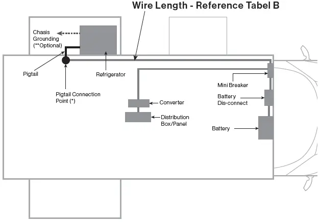
Drainage Preparation
The cavity condensate drainage is captured in a drain pan integrated with the unit. No external drainage needs to be prepared at this point.
Installing the Refrigerator
Electrical Connection
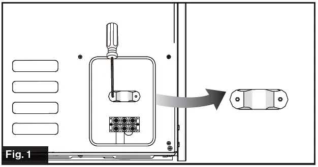
- Remove the strain relief and connector cover using a Phillips screwdriver. (Fig. 1)

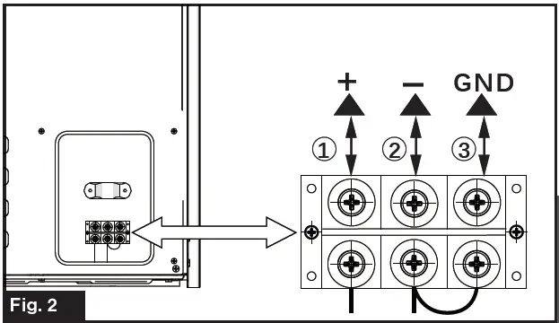
- Connect the cables to the correct terminals as shown in Fig. 2. Connect the terminal “+” to the 12V DC positive pole connect the terminal “-” to the 12V DC negative pole.
- Connect additional chassis grounding to the Terminal block labeled “GND” if desired.
- Fix the cable with the strain relief and replace the connector cover. (Fig. 3)
Installation without Sidewall Access
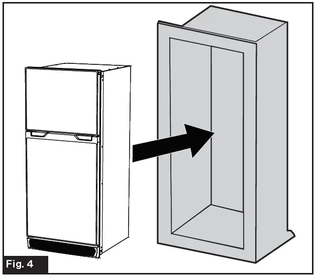
- Slide the unit into the enclosure. Care should be taken to avoid rubbing the chassis and wire together during installation. (Fig. 4)
NOTE: Elevating the wire and use of wire sheathing/wire loom will help protect the wire.
- Unscrew the air vent fixing screws and remove the air vent. (Fig. 5)
- Center the fridge in the opening to ensure the trim covers all front gaps in the cabinet.
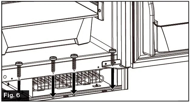
- Affix the refrigerator into the enclosure on both the top and bottom. (Fig. 6 and Fig. 7)
NOTE: Use the appropriate wood style screw to bite into the softwood portion of the cabinet framing.
NOTE: Do not mount the top or bottom first, and push the free end of the refrigerator cavity to square up in the enclosure. Doing so will mis-align door the latches. If the cabinet is out of square, shim appropriately.
- Reinstall the air vent and tighten the screws. (Fig. 8)

Installation with Sidewall Access
NOTE: Follow the below steps where a sidewall vent or access panel is available, such as when replacing an existing gas absorption refrigerator.
- Place refrigerator in the enclosure, described in Fig. 4 from the “Installation without Sidewall Access” section. Disregard any electrical connections at this step
- Remove the existing sidewall vent or open the sidewall access panel, for access to the rear of the appliance.
- Confirm location of the wire and that no interference with the refrigerator chassis frame will cause an abrasion or pinch on the wire. Relocate the wire if necessary, it should be within the ¼” space between the back of the unit and cabinet. Refer to “Electrical Preparation” of this manual for further detail.
- Inspect fit of the refrigerator to the cabinet. Push tight into position.
NOTE: Sealing foam may be interfering in the rear and will require removal of contact locations with a knife. - Affix the refrigerator to the cabinet following steps 2 – 5 in section “Installation without Sidewall Access”.
- If applicable, cap and seal the gas line with a ⅜” flange fitting plug. Turn the gas on and check for any gas leaks using a non corrosive liquid leak detection solution.
- Make the electrical connection as described in “Electrical Connection” section.
- If necessary re-seal any openings that were revealed from cutting away the foam in step 3 that may prevent moisture leakage/propagation.
NOTE: Foaming/sealing gaps along the perimeter of the refrigerator sides and bottom is not necessary.
Reversing the Door Swing (Optional)
Your refrigerator is ordered as either a left or right open swing from the factory, you may change the door swing direction as required.
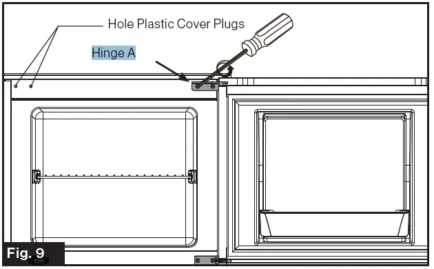
- Disassemble the freezer door by removing the Hinge A fixing screws. (Fig. 9) Remove the Hole Plastic Cover Plugs from the left side of the refrigerator and set aside for future use.

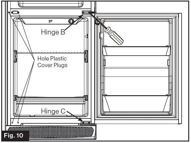
- Disassemble the Refrigerator Door by removing the Hinge B and Hinge C fixing screws. (Fig. 10)
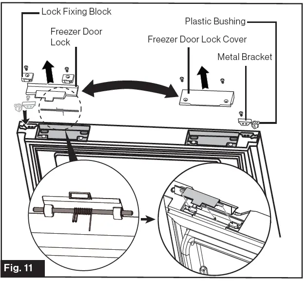
- Reverse the parts of Freezer Door Lock Cover, Metal Bracket, Plastic Bushing, Freezer Door Lock, Lock Fixing Block to the opposite side respectively. (Fig. 11)
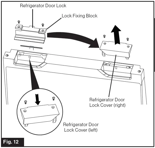
- Remove the Refrigerator Door Lock Cover (right) and save it for future use. Change Refrigerator Door Lock and Lock Fixing Blocks to the opposite side. Install the left side Refrigerator Door Lock Cover, provided as an accessory with the unit, where the door lock was. (Fig. 12)
- Reverse the Metal Bracket and Plastic Bushing on the bottom of Refrigerator Door. (Fig. 13)
- Unscrew the Door Latch Bracket fixing screws and change it to the opposite side. (Fig. 14)

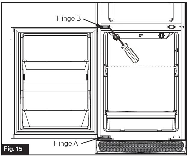
- Fix the Hinge A at the bottom left. Reinstall the Refrigerator Door and fix the Hinge B to the left side of the middle beam. (Fig. 15)

- Reinstall the Freezer Door and then fix the Hinge C at the top left. (Fig. 16)
Door swing change is complete, now check for proper alignment. Feel for any binding, or misalignment of the door, and make certain the latch is catching and releasing correctly. Slight adjustments can be made by loosening and adjusting the hinges if needed.
NOTE: The instructions above are for changing the door open direction from the left to the right. By reversing the above steps, you can change the door open direction from right to left.
Operation
The appliance has a low-voltage shut-off function, intended to protect your RV battery’s from excessive drain.
NOTE: This function controls compressor operation only, a small electric current is still used for the LED cavity light and low-voltage monitoring system. Once voltage is increased, the system will automatically begin normal operation.
Temperature Control
Proper food storage temperatures is important to reduce the risk of foodborne illness bacteria.
The temperature control knob is located in the fresh food compartment of the refrigerator. It is designed to set the temperature from cold to coldest or turn the refrigeration system off.
The recommended operating temperatures for proper food storage is as follows:
| Compartment | Temperature |
| Fridge | 36°F~40°F (2°C~4°C) |
| Freezer | < 0°F (< -18°C) |
Turn the thermostat to max when first starting the refrigerator and after putting large quantities of food in. After a few hours turn it down between mid and max position to reach the recommended operating temperature setting. This will ensure the cabinet is thoroughly chilled before food is placed into the refrigerator. Placing large amounts of food may require additional cooling time to bring the temperature down. Several conditions may require adjustment of the temperature dial, use the following chart as a guideline.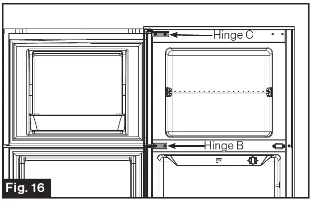
| Thermostat Setting | Fridge Temperature | Freezer Temperature |
| Max | 30°F(-1.1°C) | -11.2°F(-24°C) |
| Between Max and Mid | 39.2°F(4°C) | 1.4°F(-17°C) |
| Mid | 43.7°F(6.5°C) | 5°F(-15°C) |
| Between Mid and Min | 45.5°F(7.5°C) | 6.8°F(-14°C) |
| Min | 46.4°F(8°C) | 8.6°F(-13°C) |
| NOTE: The above chart is a guideline defined based on ideal ambient conditions of 77°F(25°C). Several factors can alter the performance, a refrigerator thermometer should be placed to achieve maximum performance. | ||
NOTE: If power is lost during operation, the refrigerator will automatically resume operation after 3 to 5 minutes. The temperature knob does not need to be adjusted or cycled to restart the refrigerator.
Off Grid Usage
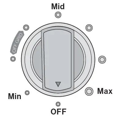
- Where grid power is not available, the “OFF GRID” setting can be used to maximize battery life.
- During travel, where a tow vehicle will provide constant battery charging, it is recommended to operate the refrigerator at a normal temperature setting dial (refer to “Temperature Control” section). Once you have arrived and are dependent on your battery reserve, rotate the knob to the “OFF GRID” setting of the dial.
- It is recommended to store meat and dairy products towards the back and middle shelf of your refrigerator. Utilize the other space of the refrigerator for beverages, condiments, and produce.
NOTE: Operation time of refrigerator in “OFF GRID” mode depends on, but not limited to, factors such as; ambient temperature, battery capacity, condition of battery, thermostat setting, food qty, and frequency of door openings. Reference the below chart to adjust operation time based on ambient temperature.
| Ambient Temperature | Operation Time |
| 68°F(20°C) | 100% |
| 77°F(25°C) | 80% |
| 90°F(32.2°C) | 55% |
| 110°F(43°C) | 25% |
Extreme Temperature Usage
The normal operating temperature for this appliance is 50°F (10°C) to 109.4°F (43°C).
The refrigerator can be used in ambient temperatures between 109.4°F (43°C) and 125.6°F (52°C), but expect reduced cooling performance. If the ambient temperature exceeds 125.6°F (52°C), allow the inside of the coach to cool down before turning on. If the ambient temperature is below 50°F (10°C), the dial control may need to be turned towards max to operate the refrigerator. The freezer can be operated with ambient temperatures below 32°F (0°C), but expect the refrigerator to be frozen. Furrion recommends increasing the ambient temperatures above 50°F (10°C) for best results.
Adjusting the Shelf (Optional)
To avoid the possibility of child entrapment, do not remove any shelf from the refrigerator. Shelving is intended to deter children from play in the compartment area.
The refrigerator and freezer shelves are fixed in the compartments from the factory. Shelving adjustment is possible with the following Instruction:
NOTE: The instructions will walk through the freezer compartment shelving, but apply to all shelving.
To adjust the freezer compartment shelf position:
- Open the compartment door. (Fig. 17)
- Lever the shelf fixing screw cover using a sharp tool. (Fig. 18)

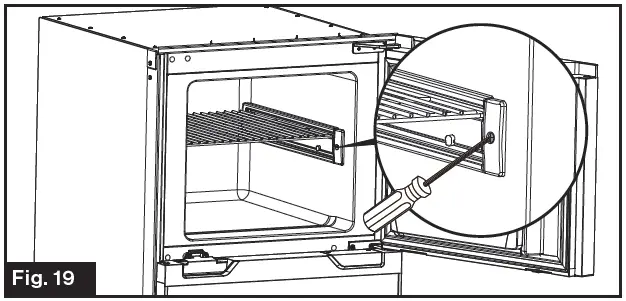
- Loosen the fixing screw using a Phillips screwdriver. (Fig. 19)

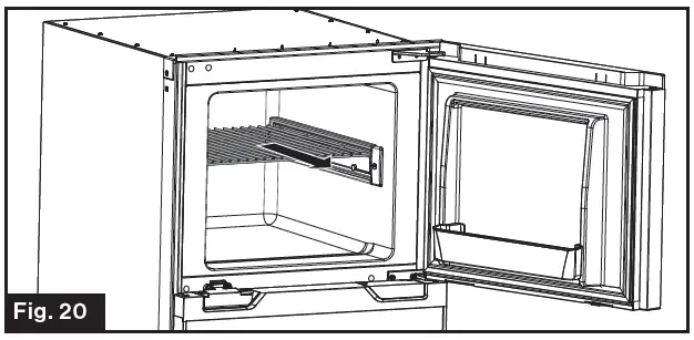
- Repeat steps 2 and 3 to loosen the shelf fixing screw on the other side. Pull to remove the shelf out from its original position. (Fig. 20)
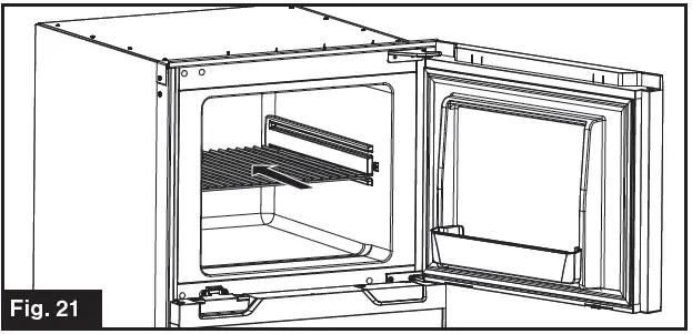
- Slide the shelf into an appropriate position and fix with screw. (Fig. 21)
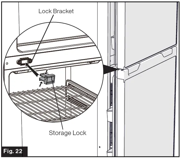
Storage Lock
Utilize the Storage Lock, provided in the accessories package with the unit, to prop the door open during extended storage. This will provide air flow throughout to reduce moisture and odors.
NOTE: It is not recommended to leave the Storage Lock in position during traveling, vibration may shake the latch loose.
- Press the Storage Lock onto the lock bracket directly to install it.
- Press both sides of the Storage Lock as per the arrows shown in Fig. 22 and pull to remove the Storage Lock.
- Close the doors so that the door latch engages with the storage lock.
Transportation
Your refrigerator is designed to operate during normal transportation of your coach. Please refer to the following guidelines to assist during transportation.
- During long trips, leave your refrigerator off until 3 hours before your destination arrival. This will help reduce any moisture/ice accumulation and accidental battery discharging.
- Avoid traveling with food in the cavity. Wait until you have arrived to your destination and remove any remaining food before departing.
- Never transport with the Storage lock in place.
- Turn refrigerator to “OFF” if climbing/crawling any off-road grades. Compressor oil should resettle within 2 hours.
Energy Saving Tips
- When possible, place your coach or refrigeration in a position to avoid direct sun.
- Cool down the hot food to normal temperature before putting them into the refrigerator.
- Be sure to wrap foods properly, and wipe containers dry before placing them in the refrigerator. This could prevent frost buildup inside the refrigerator.
- Organize and label the food to reduce door openings and long time searches.
Extended Storage
Any time the unit is not to be in-use, it is considered “extended storage”. Follow the below steps to properly prepare the unit for storage:
- Remove all food and turn the dial to off.
- Let any accumulated ice thaw, and dry out with a towel.
- Disconnect power(either via main disconnect switch, and turning the converter off or fuse).
- Remove charcoal filter to preserve charcoal activation, replace with a new filter every season or after three months of active use.
- Install door Storage Lock. See the “Storage Lock” section about how to install the Storage Lock.
Cleaning and Maintenance
Cleaning Refrigerator Interior
It is recommended to clean the interior as needed due to spills and other cleaning needs, or each time a new charcoal filter is replaced.
Cleaning your Door Panels
Keep the refrigerator outside clean. Wipe with a clean cloth lightly dampened with kitchen appliance wax or mild liquid dish detergent. Dry and polish with a clean, soft cloth.
Do not wipe the refrigerator with a soiled dish cloth or wet towel. These may leave a residue that can erode the paint. Do not use scouring pads, powdered cleaners, bleach or cleaners containing bleach because these products can scratch and weaken the paint finish.
Battery Maintenance
Your refrigerator has an automatic shut-off switch, should the voltage drop below 9.6V at the terminal connection. This is to help prevent permanent damage to your batteries.
NOTE: Once voltage is re-established the refrigerator will begin working automatically per the setting of the dial. When possible maintain the float voltage listed on your battery. Solar is a good way to maintain battery voltage if
a local power source is not available. Contact Furrion for further questions or options on Solar.
Replacing the Interior LED
Electric Shock Hazard
Remove power to the refrigerator by turning off the converter, disconnecting the battery main, or pulling the fuse. Failure to do so may result in electrical shock or personal injury.
Before removing the LED, turn the refrigerator temperature control to the OFF position. Replace the old LED with a new LED of the same wattage and size. Contact Furrion or Furrion authorized dealer to purchase a genuine Furrion replacement LED (C-FCR10DCDTA-S01).
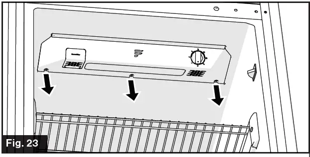
- Unscrew the three screws (Fig. 23)
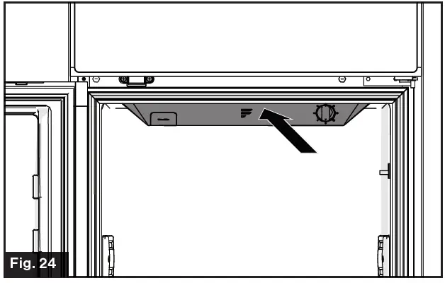
- Press the cover backwards toward the rear of the unit and open it. (Fig. 24)
- Remove the clip and two screws to replace the old LED with a new LED. Fix the clip and tighten the screws. Then reinstall the cover. (Fig. 25)
Replacing the Charcoal Filter
It is recommended to replace the charcoal filter every three months of active use. Contact Furrion or Furrion authorized dealer to purchase the replacement charcoal filter (C-FCR10DCDTA-B01).
Replace the charcoal filter by pulling it out from the refrigerator as shown in Fig. 26 and replace with a new one.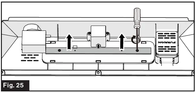
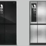
Door Panels
Furrion offers high gloss black, matte black, stainless steel and black stainless steel colors of refrigerator door panel. Contact Furrion or Furrion authorized dealer to purchase the replacement door panel.
| Replacement Door Panel | ||
| Color | Model | |
| 8 cu. ft. 12V Built-in Refrigerator | 10 cu. ft. 12V Built-in Refrigerator | |
| Stainless Steel | C-FCR08DCDTA-A01 | C-FCR10DCDTA-A01 |
| Matte Black | C-FCR08DCDTA-A02 | C-FCR10DCDTA-A02 |
| High Gloss Black | C-FCR08DCDTA-A03 | C-FCR10DCDTA-A03 |
| Black Stainless Steel | C-FCR08DCDTA-A04 | C-FCR10DCDTA-A04 |
Refrigerator Door Panel
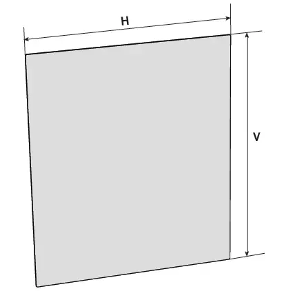
When replacing the refrigerator door panel, the following dimensions should be met: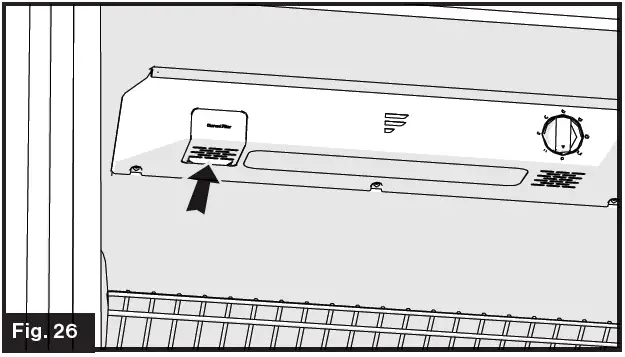
| Model | H | V | T |
| 8 cu. ft. 12V Built-in Refrigerator | 273/4″±1/16″ | 233/4″±1/16″ | 3/16″ |
| 10 cu. ft. 12V Built- in Refrigerator | 343/4″±1/16″ | 233/4″±1/16″ | 3/16″ |
| NOTE: “T” indicating the thickness of the replacement door panel. | |||
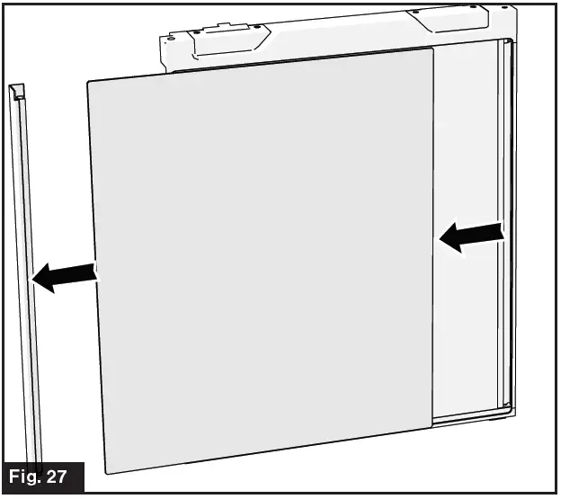
- Pull out the Side Cover. (Fig. 27)
- Slide out the Refrigerator Door Panel and replace with a new one. (Fig. 28)
Replacing Freezer Door Panel
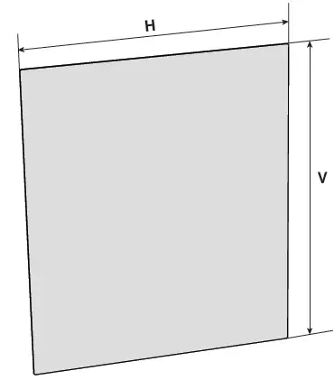
When replacing the freezer door panel, the following dimensions should be met: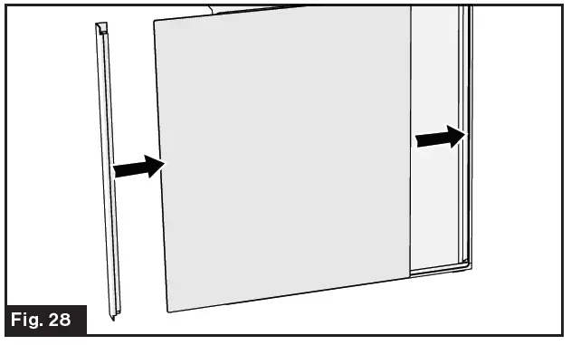
| Model | H | V | T |
| 8 cu. ft. 12V Built-in Refrigerator | 183/4″±1/16″ | 233/4″±1/16″ | 3/16″ |
| 10 cu. ft. 12V Built- in Refrigerator | 183/4″±1/16″ | 233/4″±1/16″ | 3/16″ |
| NOTE: “T” indicating the thickness of the replacement door panel. | |||
- Hold the right of the Top Cover and lift upward to remove.
- Take off the Side Cover. Slide out the Freezer Door Panel and replace with a new one. Reinstall the Top Cover and Side Cover. (Fig. 30)

Circuit Diagram
Specifications
| Specifications | ||
| 8 Cu. Ft. 12V Built-In Refrigerator | ||
| Capacity (cu. ft.) | 8 cu. ft. | |
| Product Dimensions (H*D*W) | 533/16” x 253/4” x 241/4” (1350 x 654 x 616 mm) | |
| Recessed Dimensions (H*D*W) | 5211/16” x 233/4” x 235/16” (1338 x 604 x 592 mm) | |
| Net Weight | 121Lbs (55 Kg) | |
| Rated Power Supply Voltage | DC 12V | |
| Rated Current | 11A @ start-up & maximum cooling setting | |
| Temperature Range | Fresh Food Compartment | +35.6 ~ +46.4°F (2 ~ 8°C) |
| Freezer Compartment | +21.2 ~ -0.4°F (-6 ~ -18°C) | |
| 10 Cu. Ft. 12V Built-In Refrigerator | ||
| Capacity (cu. ft.) | 10 cu. ft. | |
| Product Dimensions (H*D*W) | 603/16” x 253/4” x 241/4” (1350 x 654 x 616 mm) | |
| Recessed Dimensions (H*D*W) | 5911/16” x 233/4” x 235/16” (1338 x 604 x 592 mm) | |
| Net Weight | 134Lbs (61 Kg) | |
| Rated Power Supply Voltage | DC 12V | |
| Rated Current | 11A @ start-up & maximum cooling setting | |
| Temperature Range | Fresh Food Compartment | +35.6 ~ +46.4°F (2 ~ 8°C) |
| Freezer Compartment | +21.2 ~ -0.4°F (-6 ~ -18°C) | |
| Typical Runtime (Off Grid Usage, powered by 100amp/hr battery) | 49 hours @ 77°F (25°C) | |
| 31 hours @ 90°F (32.2°C) | ||
Troubleshooting
A qualified professional is required for any servicing of the compressor drive board and the control board, otherwise it will void the product warranty. If you encounter a problem similar to what is mentioned in the following table, try the suggested solution below to see if you can solve the problem before calling service.
| Problem | Solution |
| Refrigerator does not work | The circuit breaker tripped or fuse blown. |
| The unit temperature control dial is set to the “OFF” position. | |
| Battery voltage might be out of operating range. Check battery voltage for 10.5V under load. | |
| Compressor turns on and off frequently | The room temperature might be elevated. |
| The door is open or is frequently opened. | |
| The temperature control dial is not set correctly. | |
| The door gasket is torn or not sealing properly. | |
| Battery voltage might be low, and dropping out of operating range. Check battery voltage for 10.5V under load. | |
| Refrigerator compartments are too warm | Temperature control dial is not set correctly (see the “Temperature Control” section on page 10 for instructions on setting the temperature). |
| The door is open or is frequently opened. | |
| The door gasket is torn or not sealing properly. | |
| A large amount of warm or hot food was stored recently. Wait for the refrigerator to reach its selected temperature. | |
| The refrigerator has recently been disconnected for a period of time. | |
| Vibrating or rattling (slight vibration is normal) | The refrigerator is placed on uneven or weak surface. |
| Temperature setting, such as max position, may affect the vibration level. Refer to the “Temperature Control” section on P10. | |
| Moisture or ice inside the refrigerator | The door is open or is frequently opened. |
| Temperature control dial is set at too cold of a position | |
| Moisture forms on the outside of refrigerator | This is normal in hot and humid weather. |
| Bubbling or gurgling sounds (like boiling water) | This is the normal sound of refrigerant (used to cool refrigerator) circulating throughout the system. |
| Popping or cracking sounds when compressor comes on | This is normal for metal parts to undergo expansion and contraction, like hot water pipes. |
| The door can’t be closed properly | The refrigerator is not on a level surface. |
| The door was reversed and not properly installed. | |
| The gasket is dirty or bent. | |
| The storage basket, shelves, and bins are not seated properly. |
![]()