![]()
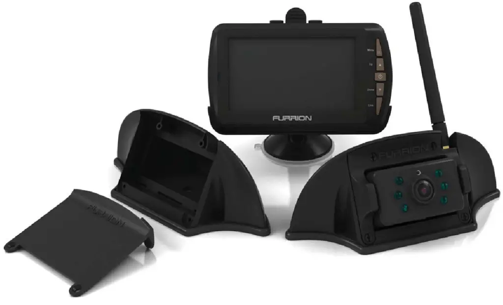
Furrion Digital Wireless Camera System
Designed for 5th Wheel, 1W, Caravan, and Trailer applications Furrion’s new easy install wireless camera kit comes in two parts,
- Furrion mount bracket prep kit. Part No. FRCBRKT-BL
- Furrion Camera and Monitor Kit. Part No. FRC12TA-BL
Check if your RV or Trailer has been pre-installed with the mounting bracket prep kit.
Safety Instructions
Please read these instructions carefully before installation and operating your Furrion reversing camera unit.
The following symbols are used throughout this manual to indicate potentially dangerous situations or mark important safety instructions.
 WARNING: Indicates a potentially dangerous condition. Use extreme caution when performing this task.
 CAUTION: Indicates a critical procedure for the safe and proper operation of the controller.
 NOTE: Indicates a procedure or function that is important for the safe and proper operation of the controller.
General Safety Information
- Read all of the instructions and cautions in the manual before beginning installation.
- There are no user-serviceable parts inside the Furrion Rear camera system Do not disassemble or attempt to repair any part of the camera system.
- Disconnect all sources of power to the camera before installing.
- There are no fuses or disconnects on the Furrion reversing camera unit. Install external fuses/breakers as required.
- Do not allow water to enter the LCD Display.
- Connect 12/24V power cable to the camera unit u§ing waterproof
Excessive heat can be caused by a loose connection.
Caution:
A battery or 12/24V DC electrical system presents a risk of electrical shock or burn hazard. Ensure all power sources are isolated before installation.
Warning:
These installation instructions are for use by qualified personnel only. To reduce the risk of electric shock, do not perform any servicing other than that specified in the operating instructions.
Caution:
To reduce the risk of fire, connect the camera only to a circuit provided with a maximum branch-circuit overcurrent protection device.
Note:
Ensure watertight connectors which connect the camera power supply cable to a power source.
Warning:
Use 16AWG or larger cables to supply power to the camera unit.
V Warning:
Ensure to connect the rear camera to the correct polarity 12/24V DC power supply. Red = Positive.
Installation Safety Precautions
Use correct size cable and connectors for supplying power to your rear camera
Ensure the power supply circuit has circuit protection Connect the rear camera to an 8-30V DC circuit only
Use insulated tools when working with power supply
Use correct safety equipment when working at elevated levels
Ensure the camera prep bracket gasket is correctly sealed and weatherproof.
Ensure correct polarity of DC power supply to camera Objects in the monitor may appear closer than they appear. Reverse slowly and with care.
This rearview camera system is designed to assist the driver, it is not designed to replace rearview mirrors. Always check your mirrors.
General information
Overview:
Thank you for purchasing a Furrion reversing camera system.
Furrion’s reversing camera system is one of the easiest rearview camera systems to install in your trailer, truck, or RV. All that is required is a connection of a single DC power supply to the rear camera from a reversing power source.
The Furrion reversing camera system is using digital wireless technology giving the major benefit of superior signal transmission with low interference on a single bandwidth channel. This means the Furrion camera unit eliminates the interferences which other analog signal systems are subject to, meaning the Furrion digital system gives you a clearer picture of what is behind you no matter where you are.
This Furrion system with an integrated antenna attached to the camera has been specifically designed for use on trailers, trucks, 5th wheels, caravans, and RV’s. This system has been designed for extended range applications or security monitoring.
Features:
This unit can be used as a reversing camera, tow hitch monitor or security monitor.
This unit features:
Wide-angle viewing lens
Night vision LED lights
Camera mounting bracket to reduce glare
Digital wireless signal for clear picture quality
Easy installation
Adjustable camera angle
Installation
FRCBRKT-BL
Furrion reversing camera mounting bracket installation:
The Furrion reversing camera prep kit includes:
1 x Reversing camera mounting bracket
1 x Mounting bracket gasket
1 x 6ft power cable
1 x Removable Bracket cover
When wiring the Furrion camera system as a rearview camera, the power supply for the camera unit must come from a 12V trigger power source or transmission wiring. The power source can also come from the 7 way connection from your trailer.
For reversing camera use, mount the camera bracket in an elevated position at the rear of the trailer or RV.
Do not mount the camera in a low position.
For reversing the camera function, do not connect the camera to a constant power source.
or best results, mount the camera in a high position to increase the viewing angle.
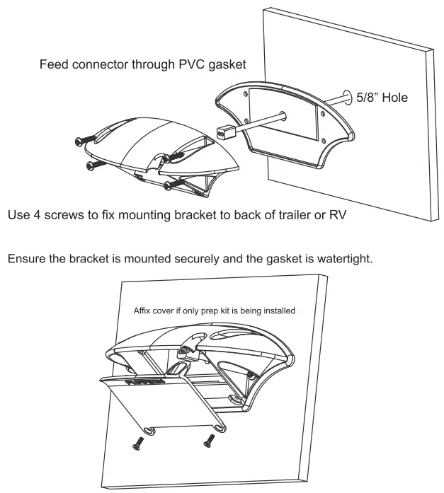
Mounting and wiring the camera prep bracket kit
Wiring:
For using your camera kit as a reversing camera system:
- Isolate the 12V power system
- Find a suitable position to mount your camera mounting bracket on the rear of your trailer/coach/truck. Ensure the mounting position is centered and in an elevated position at the top area. The higher the bracket is mounted the better the viewing angle of the camera will be.
Ensure there are no running lights or objects protruding directly under the position for mounting which will obscure camera vision.
- Drill a hole large enough to run the 16AWG 2 core cable supplied with the mounting bracket. Ensure after drilling the hole to remove sharp edges or burrs from the edges to prevent cable damage.
- Before running the 12V supplied power cable through the hole, ensure to feed the supplied 6ft power cable through the hole in the bracket gasket per the picture on page 8. (ensure to have the center square on the gasket facing out to the cable connector)
- To provide power to the wireless rearview camera you will need to run a 16AWG 2 core internal cable from your 12V trigger source on the rear of your trailer/coach/truck, Furrion supply a 6ft 12V power cable provided with the mounting bracket, the added cable may be required if the distance to the trigger power supply is not long enough to reach the trigger source.
- When connecting the cable to the 12V power source ensure to connect (+ to Red) and (— to Black)
- Attach the camera prep mounting bracket using 4 screws to ensure the gasket is lined up correctly. Ensure the bracket is mounted tightly to ensure

Mounting bracket installation
 * If the camera bracket is being mounted as a prep kit without the camera. secure the wire connector inside the bracket and attach the cover. (as above)
Installation of camera
If your RV or trailer has a Furrion reversing camera prep kit pre-installed by the OEM manufacturer. You will need to contact your local dealer or go to furrion.com to purchase a Furrion FRC12TA-BL Camera and monitor installation kit.
To install the camera onto a pre-installed mounting bracket:
- Remove the cable cover which is held by 4 screws on the underside of the bracket
- Locate the connector inside the prep kit mounting bracket
- Connect the camera plug and socket together and install the camera with the 4 screws
See below:

Monitor Installation
When choosing a location to mount the monitor, make sure the monitor is in an area that will not obstruct your vision while driving.
- Before mounting the monitor, clean the mounting surface well.
- Position the suction mount to the smooth surface which suits your
- Press the suction cap against the smooth surface and press the lockdown to attach and fix the mount to the surface.
 Snap-in the monitor to the suction mount.
- Adjust the mounting arms to suit your view angle to the monitor and tighten the screws on the mount to fix the position.
- Route the power cable to the vehicle’s cigarette lighter socket/12/24 V power outlet. The cable must not interfere with the safe operation of the
- Insert the small 12/24 Volt DC plug of the power cable into the right side of the monitor.
- Plug the 12/24 Volt cigarette lighter plug into the vehicle’s cigarette lighter
To maximize the effectiveness of the suction mount, it is recommended that the application be performed under the following conditions:
- The surface temperature should be between 21 and 38 degrees Celsius. The application below 10 degrees should be avoided.
- The application should not occur in direct sunlight.
Mounting should be protected from exposure to direct sunlight for a period of 24 hours.
NOTE: UNDER EXTREME BRIGHT LIGHT CONDITIONS, THE SCREEN IMAGE MAY TAKE A FEW SECONDS TO STABILIZE. PLEASE WAIT UNTIL THE IMAGE HAS STABILIZED BEFORE BACKING UP.
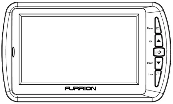
Operation
Once you have fitted the camera to your trailer, RV, truck, or caravan you will need to pair the wireless camera with the LCD monitor before use.
(This is only required at initial system commissioning to pair the camera with the LCD screen.)
| Menu | Press to show 051) or return to the previous menu |
| Up | Select forward in OSI) operation |
| Power/Confirm | Confirm or enter in OSD operation, press and hold for 2S to tum off and press to turn on |
| Down | Select backward in OSD operation, press and hold for 5S to clear pairing when there is no OSD |
| Line | Guideline display selection |
To connect camera unit and screen together:
- Ensure both the rear camera and LCD display have 12/24V DC power supplied (Vehicle may need to be running and in reverse gear to supply power to camera)
- Press the power button on the LCD display to turn on
- Press the MENU button on the display (this will bring up 4 icons on the screen)
- Using the up and down buttons scroll across to the PAIR icon
- Press the power/to confirm button (short press) (“pairing” icon will be displayed)
- Press the small button on the underside of the camera unit for 2 seconds
- On successful pairing, OK will be displayed on the LCD display.
If there is no operation of the camera displayed on the LCD display within 30 seconds of pairing. Repeat the pairing process.
Note:
If you are having trouble pairing the devices, reduce the distance between the camera unit and the LCD display for the pairing process.
To remove or replace a paired camera from the LCD display memory, Exit the menu icons on the LCD display, then press and hold down the DOWN key for 5 seconds. This will erase all pairing memory stored on the LCD display. The pairing process must be completed again for the system to function.
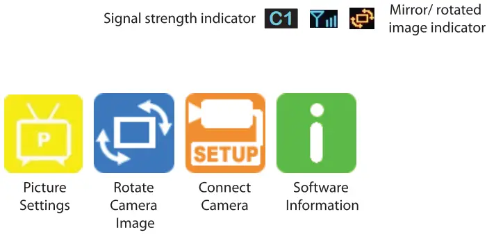
LCD Display Menu Icons:
Using the Up and Down arrow buttons on the monitor, select which icon you wish to select, then press the power button to confirm the selection.
Two Camera Option: This system can support 2 separate cameras paired to a monitor.
This feature enables two separate cameras to be paired with the same monitor. The cameras can be mounted in separate locations if required. Once both cameras are paired, use the up and down buttons on the monitor to scroll between the camera views. Both cameras require a constant power supply to enable switching views.
When two cameras are paired to the system, cameras are not required to be connected to the trigger power supply, the constant power source is required to be able to scroll between cameras using the up and down buttons on the monitor.)
WARNING:
When cameras are wired to a constant power source, do not use a monitor when driving. Driving with a monitor on can be a violation in state law. Check legislation before use.
When the pairing icon is selected, a sub-menu will be displayed showing
- Master Select
- Pair 1
- Pair 2
When Pairing 1 camera, select Master Icon
When Pairing 2 cameras, select Pair 1 and Pair 2 for each camera
LCD Picture Settings Sub Menu Icons:

| The monitor will not turn on | Ensure the power cord is connected to the display correctly Make sure the cigarette socket has a power output of 12/24V DC Check fuse in cigarette socket adapter |
| The camera and display will not pair | Check if the camera unit is receiving power Reduce the distance between camera and monitor while pairing Ensure to hold the pairing button on the camera for 2 seconds |
| This icon flashes on the display: (intermittent / weak signal) |
Check antenna is installed correctly on-cameraThe distance between camera and display is too great. Delete camera from LCD display memory then repair camera to display |
 System testing:
- Disconnect and rea tach the vehicle’s negative battery cable.
- Turn the ignition key to the accessory position, do not start the vehicle.
- Engage the parking brake, and then put the shifter in the reverse This will engage the camera unit and a picture will be displayed.
- After testing the unit and you are satisfied with the route you have chosen for the cabling, you must permanently install it.
- Route all wires behind interior panels or under carpeting so they are hidden.
Technical specification of LCD Display:
- Working voltage: DC8-30V
- Working current: 5180mA
- Standby current: 55mA
- Wireless communication distance: 00 FT (open area outdoors)
- Working frequency: 2.4GHz
- Size of LCD display: 4.3′
- Effective pixels of LCD: 480*272
- Sensitivity of receiver: -87±3dBm
- Working temperature: -10/+50
Technical specification of Camera unit:
- Working voltage: DC8-30V
- Working current: 5220mA
- Transmitting distance: .100 FT (open area outdoors)
- Size of image sensor 1/4 inch Color CMOS VGA
- Quality of image: Max.25frame/sec @ QVGA
(frame rate adjusts dynamically according to the image) - Specification of the camera: Focal length f1.7mm, aperture F2.0, IR filter 850nm
- IR emission wavelength: 850nm
- IR view distance: 1.5M
- IR LED lit condition: Brightness s2Lux
- Working temperature: -10/+50
Product: 2.4GHz Digital Wireless Camera System(FCA48TA-BL)
Trade Name: FURRION
Model Name: FRC12TA-BL
Serial Model : FCA48TA-BL, FCS43TA-BL
FCC ID :2ABH3FRC12TA-BLC
Product: 2.4GHz Digital Wireless Camera System(FCS43TA-BL)
Trade Name: FURRION
Model Name: FRC12TA-BL
Serial Model : FCA48TA-BL, FCS43TA-BL
FCC ID : 2ABH3FRC12TA-BLM
This product is backed by a Furious 12-month product warranty. See the warranty card for terms and conditions.