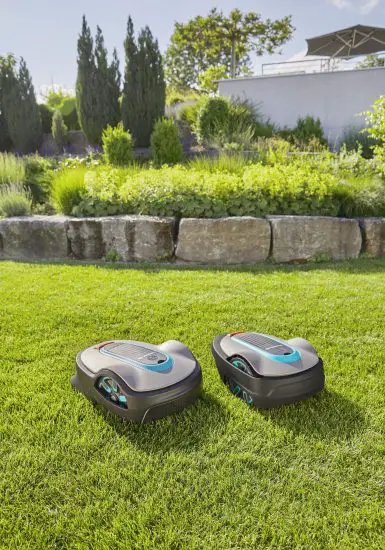
![]() Sileno City Robotic Lawn Mower
Sileno City Robotic Lawn Mower
User Guide
For more information and instructions, please read the complete supplied Operator‘s manual or visit www.gardena.com.
Installation support videos can be found on www.gardena.com.
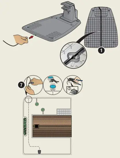
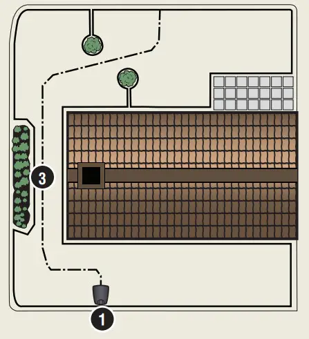
To install the charging station
- Place the charging station on a flat level surface where there is open space.
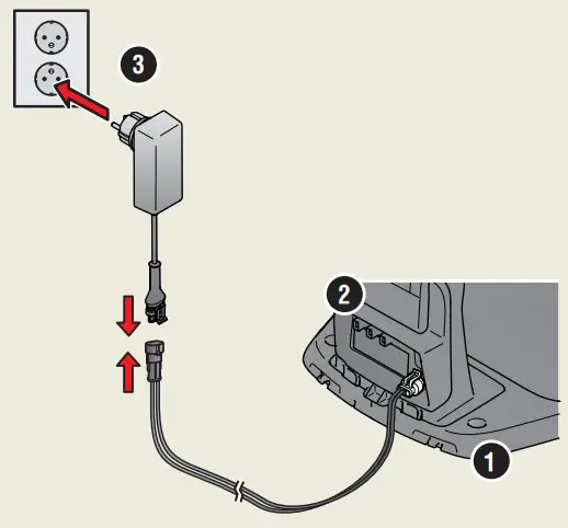
NOTE: To place the charging station in a limited space or in a corner, please read the Operator’s manual. - Connect the low voltage cable to the charging station and the power supply.
- If outdoor, put the power supply at a minimum height of 30 cm / 12 in from the ground.
- Connect the power supply to a 100-240 V wall socket.
- Place the robotic lawnmower in the charging station.
- Push the ON/OFF button to switch on the robotic lawnmower and to charge the battery while the boundary wire is laid.
NOTE: Do not continue with any product settings before the installation is complete.
To install the boundary wire
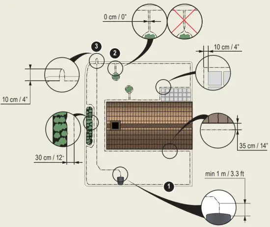
- Lay the boundary wire so that it forms a loop around the whole work area using stakes supplied or bury the wire.
NOTE: Do not lay the boundary wire in sharp bends. - Adapt the distance between the boundary wire and different objects.
A: Lay the boundary wire around all work areas in a loop.
B: High obstacles > 5 cm / 2 in e.g. wall or fence.
C: Low obstacles 1-5 cm / 0.4-2 in. or a dropped edge e.g. flower bed.
D: Objects level with the lawn 0-1 cm / 0.4 in e.g. path, paving stones.
E: Make an island to isolate areas. - Make an eyelet at the point on the boundary wire where the guidewire is later connected (F).
- To handle slopes, passages, and secondary areas, refer to the Operator’s manual.
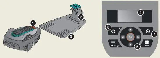
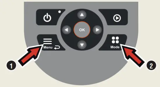
| 1. STOP button | 5. Keypad |
| 2. LED for function check of the charging station, boundary, and guide wires | 6. ON/OFF button |
| 3. Charging station | 7. Start button |
| 4. Display |

To connect the boundary wire
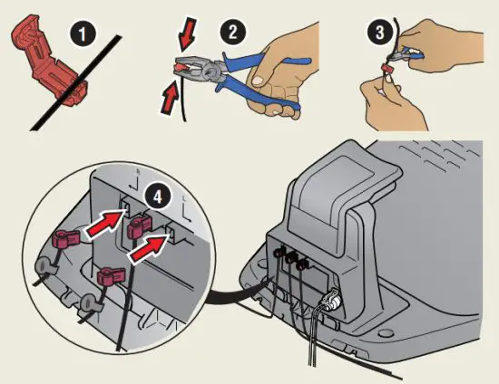
- Open the connector and lay the boundary wire in the connector.
- Press the connector and the wire together by using a pair of pliers.
- Cut off the wire 1-2 cm / 0.4-0.8 in. after the connectors.
- Press the boundary wire connectors onto the contact pins marked L (left) and R (right) on the charging station.
NOTE: The right-hand wire must be connected to the right-hand contact pin on the charging station, and the left-hand wire to the left-hand pin.
To install and connect the guide wire
Install a guidewire to lead the robotic lawn mower to remote parts of the lawn and to help it to find the charging station.
- Push the guidewire through the bottom of the charging station and fasten it into place using the snap locks.
- Fit the connector to the guidewire in the same way as for the boundary wire, according to the instructions above.
- Press the guidewire connector onto the contact pin marked GUIDE on the charging station.
- Pull the guidewire a minimum of 1 m / 3.3 ft. straight out from the front edge of the charging station.
- Lay the guidewire from the charging station to the point on the boundary wire (eyelet) where the connection is made using stakes supplied or bury the wire.
NOTE: Do not lay the guidewire in sharp bends and it cannot cross the boundary wire that for instance is laid out for an island. - Cut the boundary wire at the center of the eyelet that was made in step 2.3.
- Connect the guidewire to the boundary wire by inserting the boundary wires and guidewire in the coupler, and pressing the coupler together with a pair of pliers.
NOTE: After the guidewire is installed, attach the charging station to the ground with the supplied screws and Allen key.
NOTE: For optimal performance through narrow passages please ensure the guidewire is laid correctly through it. Please read the Operator‘s manual for
further instructions.
To start and stop the robotic lawnmower
When starting the robotic lawn mower for the first time a start-up sequence begins where you choose your language, country, date, time, and personal PIN code. There is also a guide calibration, where the robotic lawn mower automatically follows the guidewire.
To start the product
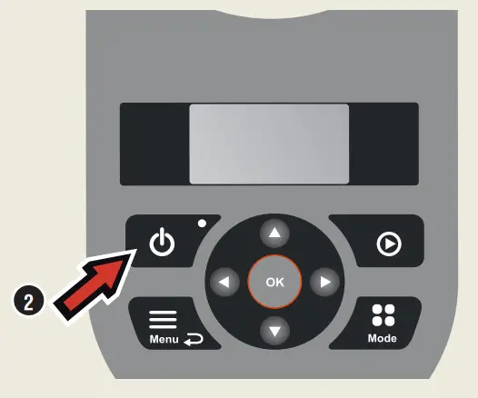
- Open the hatch to the keypad.
- Push the ON/OFF button for 3 seconds.
- Enter the PIN code.
- Select the operating mode.
- Close the hatch.
To stop the product
- Push the STOP button.
To change the settings
All settings for the robotic lawn mower are done via the menu functions. Please read the Operator’s manual and become familiar with the menus and settings.
- The Schedule function is used to adjust the mowing time to suit your work area. If the robotic lawn mower is allowed to mow too often, the grass may appear flattened. Use the scheduling wizard to set a suitable schedule. Push the Menu button and select Schedule > Wizard and enter the size of your work area. If you want to change the schedule settings for individual days use Schedule > Advanced.
- Use the Mode button to choose the operating mode, for example, Main area, Secondary area, and Park.
Test run the robotic lawn mower through narrow passages
Narrow passages in the garden can make it difficult for the mower to find the charging station. Use the Test function to test that the robotic lawn mower can travel through the narrow passage.
- Place the robotic lawnmower in the charging station.
- Select Test in the menu (Settings > Lawn coverage > More > Test) and push OK.
Then push the Start button and close the hatch. - Check that the robotic lawn mower follows the guidewire through the passage.
a.If the robotic lawn mower runs through the passage, the test is complete.
b.If the robotic lawn mower does not get through the passage: Check that the guidewire has been laid according to the instructions in the Operator’s manual.

The right to make changes without prior notice is reserved.
Copyright © 2021 GARDENA Manufacturing GmbH. All rights reserved.
www.gardena.com
Select Art. 1891
Operator’s manual
Water Control

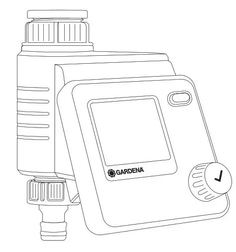
GARDENA Water Control Select
Translation of the original instructions.
For safety reasons, children and young people under 16 as well as anyone who is not familiar with these operating instructions should not use the product. Persons with reduced physical or mental abilities may use the product only if they are supervised or instructed by a responsible person. Children must be supervised to ensure that they do not play with the product. Never operate the product when you are tired, ill, or under the influence of alcohol, drugs, or medicine.
Intended use: The GARDENA Water Control is intended for private use in domestic and hobby gardens, exclusively for outdoor use, to control sprinklers and watering systems. The Water Control can be used for automatic watering during holidays. DANGER! The GARDENA Water Control must not be used for industrial purposes or in conjunction with chemicals, foodstuffs, easily flammable and explosive materials.
SAFETY
Important!
Read the operator’s manual carefully before use and keep it for future reference.
Battery:
To ensure the Water Control runs safely, only a 9V alkaline manganese battery (alkaline) type IEC 6LR61 must be used!
In order to stop the Water Control from failing because of a weak battery if you are away for a long time, the battery must be replaced when the battery symbol flashes.
Setting up:
The Water Control may only be set up vertically with the sleeve nut to the top to prevent water from penetrating into the battery compartment. The minimum water output to ensure that the Water Control functions correctly is 20 – 30 l/h. For example, at least 10 x 2-liter Drip Heads are required to control the Micro-Drip-System.
At high temperatures (over 70 °C at the display) the LCD display may extinguish. This does not affect the program in any way. When the computer cools down the LCD display illuminates again. The max. temperature for the water flow is 40 °C. Avoid tensile strain.
→Do not pull the hose connected to the Water Control.
 CAUTION! If the control section is removed when the valve is open, the valve remains open until the control section is reattached.
DANGER! Cardiac arrest!
This product makes an electromagnetic field while it operates. This field may under some conditions interfere with active or passive medical implants. To decrease the risk of conditions that can possibly injure or kill, we recommend persons with medical implants to speak with their physician and the medical implant manufacturer before you operate the product.
DANGER! Risk of suffocation! Small parts can be easily swallowed. There is also a risk that the polybag can suffocate toddlers. Keep toddlers away when you assemble the product.
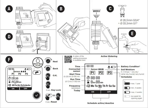
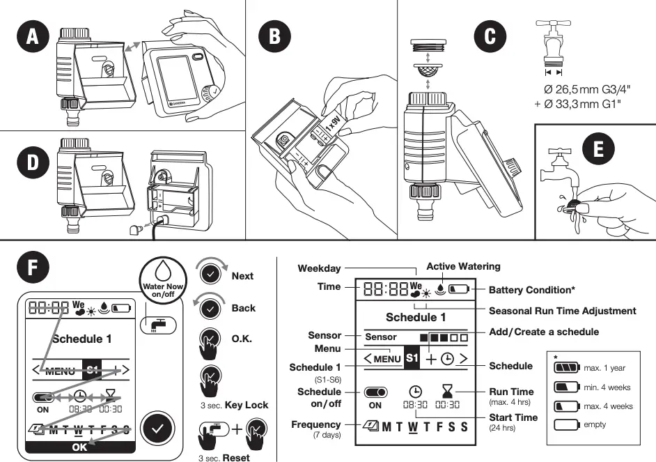
INITIAL OPERATION → (Fig. A – D)
A video of the setting processes is available here:
http://www.gardena.com/selectcontrol-video
FUNCTION → (Fig. F)
You can change the settings or move to the next setting by turning the knob. You can confirm the respective input by pressing the rotary knob. Pressing the knob for a minimum of 3 seconds locks or unlocks the display.
 max. 1 year
min. 4 weeks
max. 4 weeks
 too weak for opening again
If you will be away for long periods of time, please replace the battery when the battery symbol blinks – otherwise, the watering system may fail.
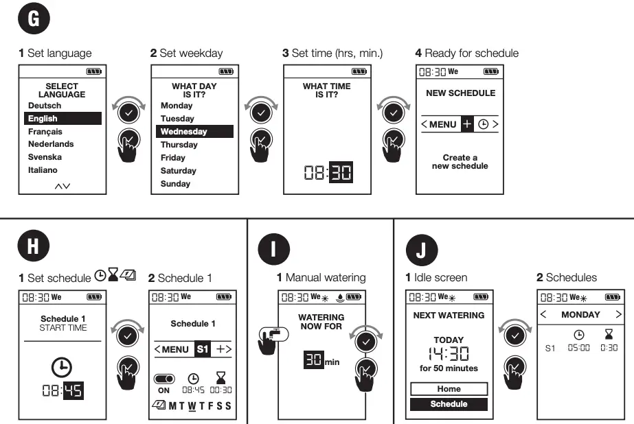
PROGRAMMING→ (Fig. G – J)
Fig. G: 1 Set time (hours) | 2 Set time (mins) | 3-day setting (Mon ‒ Sun) | 4 Ready for schedule
Fig. H: 1 Select schedule | 2 Set schedule | 3 Confirm schedule | 4 Device programmed P1, P2, P3 denotes watering schedules. You can save up to 3 independent schedules. Irrigation days must be selected and confirmed individually. The current weekday will be underlined. By pressing On / Off, schedules can be activated or deactivated individually.
Soil Moisture Sensor v (Fig. D and I):
After a soil moisture sensor is connected, the word “Sensor” will be displayed – this can take up to 1 minute.
Once the soil is sufficiently moist, a watering operation is interrupted or a schedule is disabled so that it cannot be activated. This does not affect active (manual) watering.
Soil Moisture Sensor, Art.1867 (optionally available)
1. Connecting the sensor
An operating point must then be defined.
This is the soil moisture level at or above which watering is not to be carried out (see GARDENA Soil Moisture Sensor Operating Instructions).
There are 3 levels to choose from.
– During normal operation, the currently measured level is displayed constantly.
– The switching point as of which the sensor signals that the soil is moist
– thereby preventing watering – is selected via the number of levels.
– 0 dots for loamy soil
→ Sensor response when soil is quite dry.
– 3 dots for sandy soil
→ Sensor response when soil is very moist.
Soil Moisture Sensor, Art. 1188, (optionally available, models up to 2020)
 The soil moisture level at which a watering will not be carried out as per the schedule can be set using the switching point controller on the soil moisture sensor (see GARDENA Soil Moisture Sensor Operator’s manual).
Fig. J: 1 Active watering | 2. Change watering duration |
3. Stop active watering at any time
By pressing the  button, manual watering can be started or stopped at the desired time.
A duration of between 1 minute and 59 minutes can be selected.
MAINTENANCE → (Fig. E)
STORAGE
 To put into storage:
→The product must be stored away from children.
→To preserve the battery, it should be removed (fig. B).
→Store the controller and the valve unit in a dry, enclosed and frost-free place.
 Disposal: (in accordance with RL2012/19/EC)
The product must not be disposed of to normal household waste. It must be disposed of in line with local environmental regulations.
IMPORTANT!
Dispose of the product through or via your municipal recycling collection center.
Disposal of the battery:
→Please return a flat battery to a GARDENA dealer or dispose of it properly at your nearest recycling center.
Dispose of the battery only when discharged.
TROUBLESHOOTING
| Problem | Possible Cause | Remedy |
| No display appears | The battery is inserted incorrectly. | Check the polarity markings match (+ / –). |
| The battery is flat. | Insert a new (alkaline) battery. | |
| The temperature on the display is higher than 70 °C. | The display appears after the temperature has dropped. | |
The display shows when the button is activated when the button is activated |
Buttons have been locked. | Press the √ button for 3 seconds. |
Manual watering is not possible using the  button button |
Low battery is continuously displayed. | Insert a new (alkaline) battery. |
| The tap is turned off. | Turn the tap on. | |
| The controller is not connected. | Mount the controller on housing. | |
| A minimum pressure of 0.5 bar is not available. | Ensure a pressure of at least 0.5 bar. | |
| Watering program is not being undertaken (no watering) | Program entry/modification during or just before the start pulse. | Make program entry/modification outside The programmed start times. |
| Valve was opened manually previously. | Avoid possible program overlaps. | |
| Tap is turned off. | Turn the tap on. | |
| Soil moisture or rain sensor registers damp. | If dry, check the setting/location of the soil moisture/rain sensor. | |
| The controller is not connected. | Mount the controller on housing. | |
| Low battery is continuously displayed. | Insert a new (alkaline) battery. | |
| Watering program is not being undertaken (no watering) | The tap is turned off. | Ensure a pressure of at least
0.5 bar. |
| Water Control does not close | The minimum quantity of water drawn is less than 20 l/h. | Connect more drip heads. |
| Valve soiled. | Flush in the opposite direction to the normal flow direction. |
NOTE: For any other malfunctions please contact the GARDENA service department.
Repairs must only be done by GARDENA service departments or specialist dealers approved by GARDENA.
TECHNICAL DATA
| Water Control | Value / Unit |
| Min. / max. operating pressure | 0.5 bar / 12 bar |
| Operating temperature range | 5 °C to 50 °C |
| Flow medium | Clear freshwater |
| Max. liquid temperature | 40 °C |
| Program-controlled watering sequences per day | 3 |
| Program- controlled watering sequences per week | max. 21 |
| Watering duration | 3 x 1 min. – 7 hrs 59 min. |
| Battery required | 1 x 9V alkaline manganese Typ IEC 6LR61 |
| Operating time of the battery | approx. 1 year |
ACCESSORIES
| GARDENA Soil Moisture Sensor | Art. 1867 |
| GARDENA Anti-theft device | Art. 1815-00.791.00 from the GARDENA Service |
SERVICE / WARRANTY
Service: Please contact the address on the back page. Warranty Statement:
In the event of a warranty claim, no charge is levied to you for the services provided. GARDENA Manufacturing GmbH grants a warranty for all original GARDENA new products for two years from the date of original purchase from the retailer, provided that the devices have been for private use only. This manufacturer’s warranty does not apply to products acquired second-hand. This warranty includes all significant defects of the product that can be proved to be material or manufacturing faults. This warranty is fulfilled by supplying a fully functional replacement product or by repairing the faulty product sent to us free of charge; we reserve the right to choose between these options. This service is subject to the following provisions:
- The product has been used for its intended purpose as per the recommendations in the operating instructions.
- Neither the purchaser nor a third party has attempted to open or repair the product.
- Only Original GARDENA replacement parts and wear parts have been used for operation.
- Presentation of the receipt.
Normal wear and tear of parts and components (such as blades, blade fixing parts, turbines, light bulbs, V-belts / toothed belts, impellers, air filters, spark plugs), visual changes, wear parts, and consumables are excluded from the warranty.
This manufacturer’s warranty is limited to the replacement and repair of products in accordance with the abovementioned conditions. The manufacturer’s warranty does not constitute an entitlement to lodge other claims against us as a manufacturer, such as for damages. This manufacturer’s warranty does not, of course, affect statutory and contractual warranty claims against the dealer/retailer.
The manufacturer’s warranty is governed by the law of the Federal Republic of Germany. In case of a warranty claim, please return the faulty product, together with a copy of the receipt and a description of the fault, with postage paid to the service address.
Consumables:
Faults which occur as a result of incorrectly installed or leaking batteries are not covered by the guarantee. Damage caused by frost is not covered by the warranty.
Product liability
In accordance with the German Product Liability Act, we hereby expressly declare that we accept no liability for damage incurred from our products where said products have not been properly repaired by a GARDENA-approved service partner or where original GARDENA parts or parts authorized by GARDENA were not used.
EC Declaration of Conformity
The undersigned hereby certifies as the authorized representative of the manufacturer, GARDENA Germany AB, PO Box 7454, S-103 92, Stockholm, Sweden, that, when leaving our factory, the unit(s) indicated below is/are in accordance with the harmonized EU guidelines, EU standards of safety and product-specific standards. This certificate becomes void if the unit(s) is/are modified without our approval.
| Description of the product: | Water Control |
| Product type: | Article number: |
| Select | 1891 |
| EC-Directives: 2014/30/EU 2011/65/EC |
Hinterlegte Dokumentation: GARDENA Technische Dokumentation, M. Kugler, 89079 Ulm Deposited Documentation: GARDENA Technical Documentation, M. Kugler, 89079 Ulm Documentation technique GARDENA, M. Kugler, 89079 Ulm |
Ulm, 02.03.2020
Authorized representative

Reinhard Pompe
Vice President
Germany
GARDENA Manufacturing GmbH
Central Service
Hans-Lorenser-Straße 40
D-89079 Ulm
Produktfragen: (+49) 731 490-123
Reparaturen: (+49) 731 490-290
[email protected]
http://www.gardena.com

1891-28.960.04/1220
© GARDENA Manufacturing GmbH; D-89079 Ulm; http://www.gardena.com
![]()
![]()
Translation of the original instructions.
 For safety reasons, children and young people under 16 as well as anyone who is not familiar with these operating instructions should not use the product. Persons with reduced physical or mental abilities may use the product only if they are supervised or instructed by a responsible person. Children must be supervised to ensure that they do not play with the product. Never operate the product when you are tired, ill or under the influence of alcohol, drugs or medicine.
Intended use:
The GARDENA Water Control is intended for private use in domestic and hobby gardens, exclusively for outdoor use, to control sprinklers and watering systems. The Water Control can be used for automatic watering during holidays.
DANGER! The GARDENA Water Control must not be used for industrial purposes or in conjunction with chemicals, foodstuffs, easily flammable and explosive materials.
SAFETY
Important!
Read the operator’s manual carefully before use and keep for future reference.
Battery:
To ensure the Water Control runs safely, only a 9V alkaline manganese battery (alkaline) type IEC 6LR61 must be used! In order to stop the Water Control from failing because of a weak battery if you are away for a long time, the battery must be replaced when the battery symbol flashes.
Setting up:
The Water Control may only be set up vertically with the sleeve nut to the top to prevent water penetrating into the battery compartment. The minimum water output to ensure that the Water Control functions correctly is 20 – 30 l/h. For example, at least 10 x 2-litre Drip Heads are required to control the Micro-Drip-System.
At high temperatures (over 70 °C at the display) the LCD display may extinguish. This does not affect the program in any way. When the computer cools down the LCD display illuminates again.
The max. temperature for the water flow is 40 °C.
Avoid tensile strain.
- Do not pull the hose connected to the Water Control.
 CAUTION! If the control section is removed when the valve is open, the valve remains open until the control section is reattached.
DANGER! Cardiac arrest!
This product makes an electromagnetic field while it operates. This field may under some conditions interfere with active or passive medical implants. To decrease the risk of conditions that can possibly injure or kill, we recommend persons with medical implants to speak with their physician and the medical implant manufacturer before you operate the product.
DANGER! Risk of suffocation! Small parts can be easily swallowed. There is also a risk that the polybag can suffocate toddlers. Keep toddlers away when you assemble the product.
INITIAL OPERATION
 A video of the setting processes is available here:
FUNCTION
The Master Water Control offers two options for watering your garden automatically on a timer:
- Water 1 area of a garden with a water line e.g. using a sprinkler, the GARDENA Micro-DripSystem or the GARDENA Sprinklersystem
– or – - Operate 2 ‒ 6 water lines one after another using the GARDENA Automatic Water Distributor, Art. 1197, see Fig. O (optionally available). Each line can be activated up to once a day.
You can change the settings or move to the next setting by turning the knob. You can confirm the respective input by pressing the rotary knob. Pressing the knob for longer than 3 seconds locks or unlocks the display. If no more changes are made to the settings, the LCD display switches off after 5 minutes to save energy. To reactivate the display, actuate the rotary knob. The default display appears.

SETTINGS
Initial settings → (Fig. G):
1 Set language | 2 Set weekday | 3 Set time (hrs, min.) | 4 Ready for schedule
Active (manual) watering → (Fig. I):
1 Manual watering
Setting schedules → (Fig. H):
1 Set schedule | 2 Schedule 1
Configure and save up to 6 different watering schedules by setting the start time, duration and weekdays for each one. Schedules can be activated or deactivated by pressing on/off (see fig. H).
Default display → (Fig. J):
1 Idle screen | 2 Programs
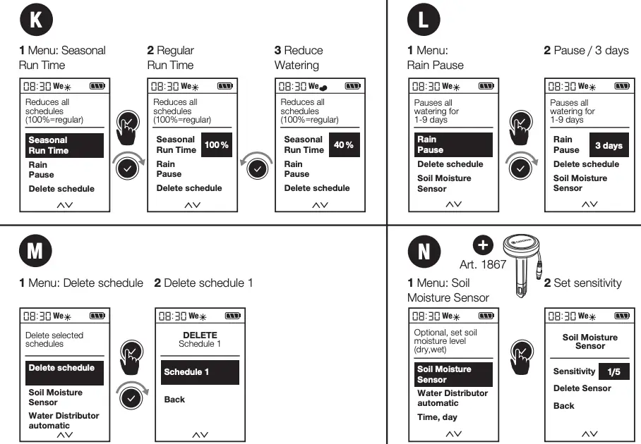
Seasonal watering duration → (Fig. K):
1 Menu: Seasonal Run Time | 2 Regular Run Time | 3 Reduce Watering
You can reduce the durations set for all schedules at once in 10% increments, from 100% down to 10%. This saves you having to change each of the 6 schedules individually.
Tip: Less watering is required in the spring and autumn than in the height of summer. Simply set the maximum watering duration for high summer as the default. Then reduce the watering duration for all schedules at once in convenient 10% increments when there is less need for watering. Note: When you change the percentage, the duration is adjusted within the schedules and the “cloud” symbol appears. If the duration is not altered (= 100%), the “sun” symbol is displayed.
Rain pause → (Fig. L):
1 Menu: Rain pause | 2 Pause / 3 days
Pauses all watering operations without changing the set schedules. You can select any number of days between 1 and 9. At the end of the pause, all schedules are reactivated.
Deleting a schedule → (Fig. M):
1 Menu: Delete schedule | 2 Delete schedule 1
Soil Moisture Sensor → (Fig. D and N):
1 Menu: Soil Moisture Sensor
Once the soil is sufficiently moist, a watering operation is interrupted or a schedule is disabled so that it cannot be activated. This does not affect active (manual) watering.

Soil Moisture Sensor, Art. 1867
(optionally available)
1 Connect soil moisture sensor
Once a soil moisture sensor has been connected, the next step is to specify the future switching point in the “Soil moisture sensor” menu. This is the soil moisture level at or above which watering is not to be carried out (see GARDENA Soil Moisture Sensor Operating Instructions).
There are 5 levels to choose from.
- During normal operation, the currently measured level is displayed constantly.
- The switching point as of which the sensor signals that the soil is moist – thereby preventing watering – is selected via the number of levels.
- 0 dots for loamy soil
- Sensor response when soil is quite dry.
- 5 dots for sandy soil
- Sensor response when soil is very moist.

Soil Moisture Sensor, Art. 1188
(optionally available, Models up to 2020)
→ (Fig. D and N):
1 Connect soil moisture sensor
After a soil moisture sensor is connected, the “sensor activated/deactivated” display will appear – this can take up to 1 minute. Select an option to activate/deactivate the sensor response. Use the switching point controller on the soil moisture sensor to set the level of soil moisture that must be achieved before the sensor responds (see Operator’s Manual for GARDENA Soil moisture sensor).
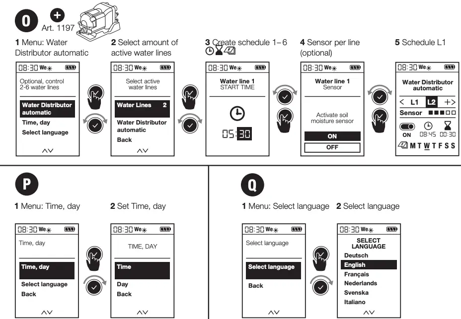
 GARDENA Automatic Water Distributor, Art. 1197 (optionally available)
→ (Fig. O): 1 Menu: Water Distributor automatic This menu allows you to control up to 6 water lines with the Automatic Water Distributor. This includes a necessary minimum pause of 5 minutes between the outlets and a minimum watering duration of 30 seconds (display: 1 min). This time ensures reliable switch-over to the next outlet and makes sure that the schedules and outlets are correctly linked (for details of the commissioning process, see the Operating Instructions for the Water Distributor).
2 Select amount of active water lines
You can select any number between 2 and 6. Seal any outlets on the Water Distributor that you do not need with end caps and move the setting lever to the “OFF” position.
3 Create schedules 1 ‒ 6
When prompted to do so, enter watering schedules L1 – L6 on the display. For this, use the standard method for entering schedules based on the start time, duration and frequency.
Note: Schedules are not allowed to overlap. If you enter a schedule that overlaps with the next one, the start time of the next watering operation will be postponed and a pause of 5 minutes will be inserted between the operations. Changes to the schedules can be made in the “Water Distributor” menu.
- Start times: Define the start times for the water lines in chronological order. This makes it easier to calculate and suggest the next possible start time.
- Duration: The total watering duration for all outlets – including the necessary pauses – must not exceed 24 hours.
- Frequency: Different weekdays can be selected. Note: To ensure correct switch-over and correct linking of the schedules and outlets, any outlets that are not scheduled to operate on a particular day will still be activated for a period of 30 seconds on the day concerned.
- Reduction in the number of outlets: If the number of outlets is reduced, the superfluous channels will be deleted. For example, if the number of outlets is reduced from 5 to 3, the settings for no. 4 and no. 5 will be deleted. The “Delete schedules” menu is not active.
- Manual watering and rain pause:
To activate a watering operation manually, press . Please note that a minimum duration of 30 seconds and a pause of at least 5 minutes must be observed. It is important to ensure that the water distributor outlets and the water control schedules are correctly linked. If this is not the case, the correct water distributor outlet will need to be set on the device.
4 Sensor per line (optional)
- If a soil moisture sensor is connected, you have the option of activating/deactivating it for each individual outlet. If the sensor is deactivated for a particular schedule, watering will always take place based on the schedule.
- If the sensor signals that the level of moisture is sufficient, any pending watering operation will be reduced to a duration of 30 seconds (display: 1 min).
5 Schedule L1
Time → (Fig. P):
1 Menu: Time, day | 2 Set time, day
Language → (Fig. Q):
1 Menu: Language preference | 2 Select language
MAINTENANCE
→ (Fig. E)
STORAGE

To put into storage:
- The product must be stored away from children.
- To preserve the battery, it should be removed (fig. B).
- Store the controller and the valve unit in a dry, enclosed and frost-free place.
 Disposal: (in accordance with RL2012/19/EC) The product must not be disposed of to normal household waste. It must be disposed of in line with local environmental regulations.
IMPORTANT!
Dispose of the product through or via your municipal recycling collection centre.
Disposal of the battery:
- Please return a flat battery to a GARDENA dealer or dispose of it properly at your nearest recycling centre.
Dispose of the battery only when discharged.
TROUBLESHOOTING
NOTE: For any other malfunctions please contact the GARDENA service department. Repairs must only be done by GARDENA service departments or specialist dealers approved by GARDENA.
TECHNICAL DATA

ACCESSORIES

Product liability
In accordance with the German Product Liability Act, we hereby expressly declare that we accept no liability for damage incurred from our products where said products have not been properly repaired by a GARDENA-approved service partner or where original GARDENA parts or parts authorised by GARDENA were not used.
EC Declaration of Conformity
The undersigned hereby certifies as the authorized representative of the manufacturer, GARDENA Germany AB, PO Box 7454, S-103 92, Stockholm, Sweden, that, when leaving our factory, the unit(s) indicated below is /are in accordance with the harmonised EU guidelines, EU standards of safety and product specific standards. This certificate becomes void if the unit(s) is /are modified without our approval.
Description of the product: Water Control
Product type: Master
Article number: 1892
EC-Directives:
2014/30/EU
2011/65/EC
Deposited Documentation:
GARDENA
Technical Documentation,
M. Kugler, 89079 Ulm
Year of CE marking: 2018
Ulm, 02.03.2020
Authorised representative

Reinhard Pompe
Vice President


1892-28.960.04/1220
© GARDENA Manufacturing GmbH; D-89079 Ulm; http://www.gardena.com
GARDENA Battery Powered Hedge Trimmer

| �1� | TECHNICAL DATA | HT 20 Li S | HT 20 Li A | |
| �2� | Power supply frequency and voltage MAX | V / d.c. | 20 | 20 |
| �3� | Power supply frequency and voltage NOMINAL | V / d.c. | 18 | 18 |
| �4� | Blade speed | spm | 2300 | 2300 |
| �5� | Blade lenght | mm | 700 | 700 |
| �6� | Cutting lenght | mm | 500 | 500 |
| �7� | Cutting capacity | mm | 18 | 18 |
| �8� | Weight without battery pack | kg | 2,2 | 2,1 |
| �9� | Cutting means code | 118805318/0 | 118805318/0 | |
| �10�
�11� |
Measured sound pressure level
Uncertainty of measure |
dB(A)
dB(A) |
75,4
3 |
75,4
3 |
| �12�
�11� |
Measuered sound power level
Uncertainty of measure |
dB(A)
dB(A) |
85,2
0,78 |
85,2
0,78 |
| �13� | Guaranteed sound power level | dB(A) | 86 | 86 |
| �14�
�15� �16� �11� |
Vibration level
– Front handle – Rear handle Uncertainty of measure |
m/s2 m/s2 m/s2 |
0,80 1,12 1,5 |
0,80 1,12 1,5 |
| �17� | ACCESSORIES AVAILABLE ON REQUEST | ||
| �18� | Battery pack, model | BT 20 Li 2.0 S
BT 20 Li 4.0 S |
BT 20 Li 2.0 A
BT 20 Li 4.0 A |
| �19� | Battery charger | CG 20 Li
CGD 20 Li CGW 20 Li |
CG 20 Li
CGD 20 Li CGW 20 Li |
- NOTE: the declared total vibration value was measured using a normalised test method and can be used to conduct comparisons between one tool and another. The total vibration value can also be used for a preliminary exposure
- WARNING: the vibrations emitted during actual use of the tool can differ from the declared total value according to how the tool is Whilst working, therefore, it is necessary to adopt the following safety measures designed to protect the operator: wear protective gloves whilst working, use the machine for limited periods at a time and decrease the time during which the throttle control lever is pressed.
1. GENERAL INFORMATION
1.1 HOW TO READ THIS MANUAL
NOTE or IMPORTANT These give details or further information on what has been previously indicated and aim to prevent damage to the machine or cause other damage.
The symbol highlights danger. Failure to observe the warning can lead to possible
personal and/or third party injury and/or damage.
The paragraphs highlighted in a dotted grey square indicate optional characteristics not available on all models documented in this manual. Check if the characteristics a re available on this model.
Whenever reference is made to a position on the machine “front”, “back”, “left” or “right” hand side, this refers to the operator’s working position.
2. SAFETY REGULATIONS
2.1 GENERAL SAFETY WARNINGS
Read all safety warnings, instructions, illustrations and specifications. provided with this power tool. Failure lo follow
all instructions listed below may result in electric shock, fire and/or serious injury.
Save all warnings and instructions for future reference.
The term “power tool” in the warnings refers to your mains-opera/eel (cordecl) power tool or battery-operated (cordless) power tool.
1) Work area safety
A Keep work area clean and well
Cluttered or dark areas invite accidents.
b) Do not operate power tools in explosive atmospheres, such as in the presence of flammable liquids,
gases or dust. Power tools create sparks which may ignite the dust or fumes.
c) Keep children and bystanders well away while using power tools.
Distractions can cause you to lose control.
2) Electrical safety
a) Avoid body contact with earthed or grounded surfaces, such as pipes, radiators, cookers and refrigerators. There is an increased risk of electric shock if your body is earthed or grounded.
b) Do not expose power tools to rain or wet environments. Water entering a power tool will increase the risk of electrical shock.
3) Personal safety
a) Stay alert, check what you are doing and use common sense when using a power tool. Do not use the power tool when you are tired or under the influence of drugs, alcohol or medicines. A moment of inattention while operating a power tool may result in serious personal injury.
b) Use personal protective equipment. Always wear eye protection. Protective equipment such as a dust mask, non-skid safety shoes, hard hat or hearing protection used for appropriate conditions will reduce personal injuries.
c) Prevent unintentional starting. Make sure the appliance is turned off before inserting the battery pack, picking up or carrying the power tool. Carrying power tools with your finger on the switch or mounting the battery with the switch in “ON” position invites accidents.
d) Remove any adjusting key or wrench before turning the power tool on. A wrench or a key left attached to a rotating part of the machine may result in personal injury.
e) Do not overreach. Keep proper footing and balance at all times. This enables better control of the power tool in unexpected situations.
f) Dress properly. Do not wear loose clothing or jewellery. Keep your hair and clothing away from moving parts. Loose clothes, jewellery or long hair can be caught in moving parts.
g) If devices are provided for the connection of dust extraction and collection facilities, ensure these are connected and properly used. Use of dust collection can reduce dust-related hazards.
6) Service
a) Have your power tool serviced by a qualified repair person using only identical replacement parts. This will ensure that the safety of the power tool is maintained.
b) Never service damaged battery packs. Service of battery packs should only be performed by the manufacturer or authorized service providers.
2.2 SPECIFIC SAFETY REGULATIONS FOR HEDGE TRIMMERS
- During work operations, always hold the machine firmly with both hands. Operating it with only one hand can cause loss of control and serious personal injury
- Keep all parts of the body away from the blade. Do not remove cut material or hold material to be cut when blades are moving. Blades continue to move after the switch is turned off. A moment of inattention while operating the hedge trimmer may result in serious personal injury.
- Carry the hedge trimmer by the handle with the blade stopped and taking care not to operate any power switch. Proper carrying of the hedge trimmer will decrease the risk of inadvertent starting and resultant personal injury from the blades.
- Hold the power tool by insulated gripping surfaces only, because the blade may come in contact with hidden wiring. Contact between cutter blades and a “live” wire may cause exposed metal parts of the tool to become “live” and give the operator an electrical shock.
- When transporting or storing the hedge trimmer, always fit the blade cover. Proper handling of the hedge trimmer will decrease the risk of personal injury from the blades.
- Do not use the hedge trimmer in bad weather conditions, especially when there is a risk of lightning. This decreases the risk of being struck by lightning.
 If something breaks or an accident occurs during work, turn off the motor immediately and move the machine away to prevent further damage; if an accident occurs with injuries or third parties are injured, carry out the first aid measures most suitable for the situation immediately and contact the medical authorities for any necessary health care. Carefully remove any debris which could cause damage or injury to persons or animals if ignored.
 Prolonged exposure to vibrations can cause injuries and neurovascular disorders (also called “Raynaud’s syndrome” or “white finger”), especially to people suffering from circulation disorders. The symptoms can regard the hands, wrists and fingers and are shown through loss of sensitivity, torpor, itching, pain and discolouring of or structural changes to the skin. These effects can be worsened by low ambient temperatures and/or by gripping the hand grips excessively tightly. If the symptoms occur, the length of time the machine is used must be reduced and a doctor consulted.
2.3 ENVIRONMENTAL PROTECTION
- Scrupulously comply with local regulations for the disposal of packaging, deteriorated parts or any elements with a strong environmental impact; this waste must not be disposed of with regular waste, but must be separated and taken to collection centres, which will recycle the materials.
- Scrupulously comply with local regulations for the disposal of waste materials
- When the machine is withdrawn from service, do not dispose of it in the environment, but take it to a waste disposal facility in accordance with the local regulations in force.
 Do not throw electrical equipment away with domestic waste. According to the European Directive 2012/19/EU on electrical and electronic equipment waste and its implementation in compliance with national standards, old electrical equipment must be collected separately, for eco-compatible recycling. If electrical equipment is disposed of in a landfill or in the ground, the harmful substances can reach the water table and enter the food chain, damaging your health and well-being. For further information on the disposal of this product, contact your dealer or a domestic waste collection service.
 At the end of their working life, dispose of batteries paying due attention to the environment. Batteries contain material classified as hazardous for you and the environment. They must be removed and disposed of separately at a facility that accepts lithium-ion batteries.
 Separate waste collection of the products and packaging used allows the materials to be recycled and reused. Reuse of recycled materials help to prevent environmental pollution and reduces the demand for raw materials.
3.ABOUT THE MACHINE
3.1 MACHINE DESCRIPTION AND INTENDED USE
This machine is a garden tool and more precisely a battery-powered portable hedge trimmer.
The machine is essentially composed of a motor which drives a cutting means.
The operator can operate the machine and use the main controls, always keeping a safe distance from the cutting means.
3.1.1 Intended use
This machine was designed and manufactured for:
- cutting and trimming bushes and hedges comprising shrubs with small branches
- being used by one operator.
3.1.2 Improper use
- Any other use that does not comply with the above, can be dangerous and cause damage to people and/or property. Examples of improper use may include, but are not limited to:
- cutting grass in general and in particular close to kerbs;
- shredding of materials for composting;
- pruning;
- using the machine with the cutting means above the operator’s shoulder level;
- use of the machine for cutting non-plant material;
- using cutting means other than those found in the “Technical Data” table. Risk of serious injury and injuries;
- using of the machine by more than one person.
IMPORTANT Improper use of the machine will void the warranty and relieves the Manufacturer of any liability, placing all responsibility for damage or injury, to him/herself or third parties, on the user.
3.1.3 Type of users
This machine is intended for use by consumers, i.e. non-professional operators. It is intended for “hobby-related activities”.
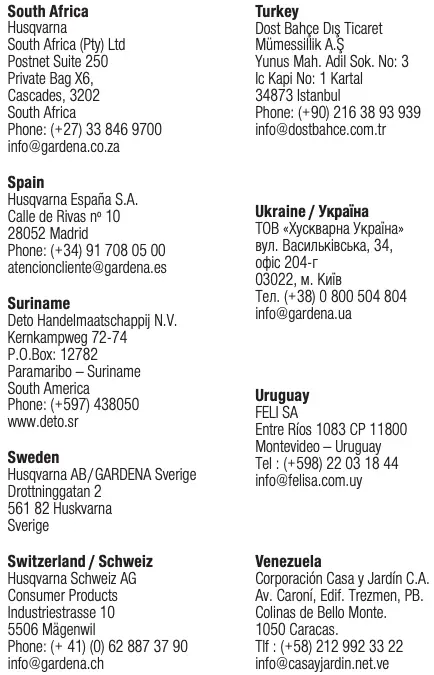
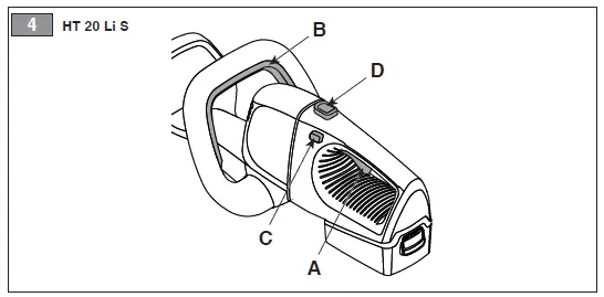
3.2 MAIN COMPONENTS (Fig.1 )
A. Engine: supplies the drive power to the cutting means.
B. Blade (cutting means): the element designed to cut the vegetation.
C. Front hand grip: used to handle the machine and equipped with the safety switch.
D. Rear hand grip: used to handle the machine and equipped with the main control buttons.
E. Blade protection (for machine transport and handling): protects against accidental contact with the cutting means that can cause serious injuries.
F. Battery (if not supplied with the machine, see chapter : 13 “optional attachments”
device that supplies electric current to the tool; its specifications and regulations for use are described in a specific manual.
G. Battery charger (if not supplied with the machine, see chapter : 13 “optional attachments” device used to recharge the battery; its specifications and regulations for use are described in a specific manual.
3.3 PRODUCT IDENTIFICATION LABEL (Fig.1 )
- CE conformity marking
- Name and address of Manufacturer
- Sound power level
- Article code
- Type of machine
- Serial number
- Year of manufacture
- Power voltage and frequency
- Blade speed
Write the identification data of the machine in the specific space on the label on the back of the cover page.
IMPORTANT Quote the information on the product identification label whenever you contact an Authorised Service Centre.
IMPORTANT An example of the Declaration of Conformity is provided on the last pages of this manual.
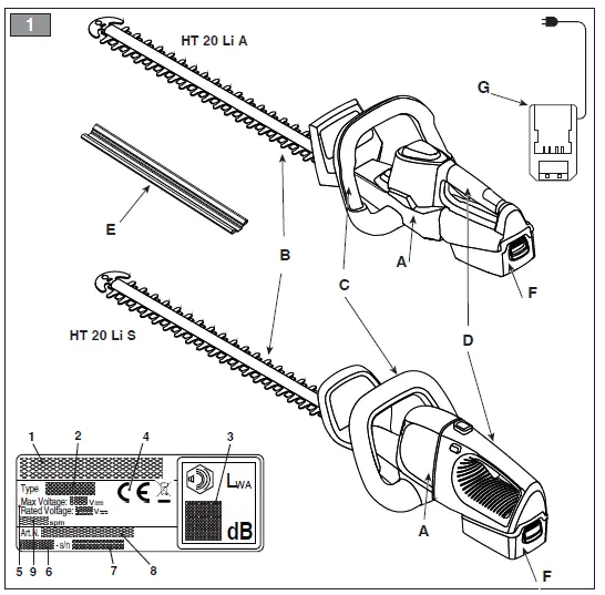
3.4SAFETY SIGNS (Fig.2 )
The machine has various symbols on it.
Meanings of the symbols:
WARNING! DANGER! The failure to use this machine correctly can be hazardous for oneself and others.
WARNING! Read the owner’s manual before using the machine.
5.3 SAFETY SWITCH
The safety switch on the front handle (Fig. 3.B, Fig. 4.B) provides additional safety, since it must be held down together with the blade control lever in order to operate the cutting device.
The cutting device stops automatically when the safety switch is released.
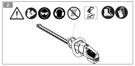
5.4 REAR HANDGRIP RELEASE BUTTON (MOD. HT 20 LI S)
The release lever (Fig. 4.D) is used to adjust the rear handgrip (Fig. 1.D) to 3 different positions in relation to the cutting means to make trimming your hedges easier (par 6.4.1).
The handgrip must only be adjusted when the machine is switched off.
IMPORTANT Any damaged or illegible decals must be replaced. Order replacement decals from an Authorised Service Centre.
4. UNPACKING
IMPORTANT The safety standards to be followed are described in chapter. 2. Strictly comply with these instructions to avoid serious risks or dangers.
Unpacking should be done on a flat and stable surface, with enough space for machine handling and its packaging, always making use of suitable equipment.
- .Carefully open the packaging, paying attention not to lose components.
- Consult the documentation in the box, including these instructions.
- Remove the machine from the box.
- Dispose of the box and packaging in compliance with local regulations.
5. CONTROLS
5.1 BLADE CONTROL LEVER
- The blade control lever (Fig. 3.A, Fig. 4.A) allows the blade (cutting device) to be operated.
- Model HT 20 Li A
Operating the cutting device is only possible if the blade control lever (Fig. 3.A) and the safety switch (Fig. 3.B) are pressed simultaneously. - Modello HT 20 Li S
Operating the cutting device is only possible if the blade control lever (Fig. 4.A) and the blade control locking button (Fig. 4.C) and the safety switch (Fig. 4.B) are pressed simultaneously.
The cutting device stops automatically when the lever is released.
5.2 BLADE CONTROL LOCKING BUTTON (MOD. HT 20 LI S)
The blade control locking button (Fig. 4.C) allows operation of the blade control lever (Fig. 4.A).
5.3 SAFETY SWITCH
The safety switch on the front handle (Fig. 3.B, Fig. 4.B) provides additional safety, since it must be held down together with the blade control lever in order to operate the cutting device.
The cutting device stops automatically when the safety switch is released.
5.4 REAR HANDGRIP RELEASE BUTTON (MOD. HT 20 LI S)
The release lever (Fig. 4.D) is used to adjust the rear handgrip (Fig. 1.D) to 3 different positions in relation to the cutting means to make trimming your hedges easier (par 6.4.1).
 The handgrip must only be adjusted when the machine is switched off.
6. USING THE MACHINE
IMPORTANT The safety standards to be followed are described in chapter. 2. Strictly comply with these instructions to avoid serious risks or dangers.
6.1 PRELIMINARY OPERATIONS
Place the machine in a stable horizontal position on the ground.
6.1.1 Checking and recharging the battery (Fig. 5)
Before each use check the battery charge status according to the instructions in the battery booklet.
6.2 SAFETY CHECKS
Always carry out the safety checks before use.
6.2.1 General check
| Object | Result |
| Handgrips (Fig. 1.C, Fig. 1.D) and guards | Are clean, dry and fixed firmly to the machine |
| Screws on the machine and blade | Correctly tightened (not loose) |
| Cooling air ducts | Not clogged |
| Blade (Fig. 1.B) | Sharp, not damaged or worn, well sharpened. |
| Guards | Intact, undamaged. |
| Battery (Fig. 1.F) | No damage to the casing, no liquid leakage. |
| Machine | No signs of damage or wear. No abnormal vibrations.
No abnormal sound. |
| Levers, buttons, and safety switches | They must move freely, not be forced and when released they must return automatically and rapidly to the neutral position. |
| Action | Result |
| 1. Start the machine
(para. 6.3 ); 2. Release the blade control lever (Fig. 3.A, Fig. 4.A) or the safety switch (Fig. 3.B, Fig. 4.B) |
1. The blade should move
2. The controls should return automatically and rapidly to the neutral position and the blade should stop |
If any of the results fail to match the indications provided in the tables below, do not use the machine! Take it to a service centre to be checked and repaired if necessary.
6.3 START-UP
Starting the machine causes the simultaneous engagement of the blade.
NOTE Operate the machine only on a firm, level surface.
- Remove the blade guard (Fig. 1.E) (if used)
- Make sure the blade is not touching the ground or any other object
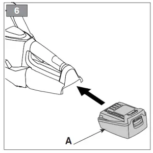
- Fit the battery (Fig. 6.A) inside its housing pressing down until you hear it clicks firmly into position and assure the electrical contact
- Take a firm and balance position
5.a Mod. HT 20 Li A
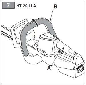
–– Simultaneously operate the blade control lever (Fig. 7.A) and the safety switch (Fig. 7.B),
5.b Mod. HT 20 Li S
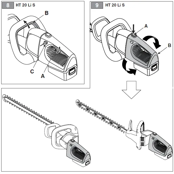
–– Simultaneously operate the blade control lever (Fig. 8.A), blade control locking button (Fig. 8.C) and the safety switch (Fig. 8.B).
6.4 OPERATION
During use, always hold the machine firmly with two hands, using the machine with the cutting means under the operator’s shoulder level.
Always use the machine at ground level and not on ladders or any other unstable support.
Do not remove cut material or hold material to be cut when blades are moving. Make sure the machine is turned off when removing cut material.
NOTE During use, the battery is protected against total drainage with a protective device that switches off the machine and stops it from working.
6.4.1Adjusting the rear handgrip (Mod. HT 20 Li S)
Perform this operation with the machine off.
- Press the rear handgrip release button (Fig. 9.A); (Fig. 9.A)
- Start rotating the rear handgrip (Fig. 9.B)
- Release the button
- Rotate the handgrip until it clicks into the desired position.
IMPORTANT Before using the machine check that the release button has correctly returned to the block position, and the rear handgrip is firmly attached.
When working, the rear handgrip must always be in a vertical position, whatever the position of the cutting means.
6.4.2 Work techniques
It is recommended to trim the two vertical sides of the hedge before trimming the top.
NOTE Battery power reserve (and therefore the cuttable vegetation area before recharging is required) depends on many factors described in (para. 7.2.1).
- Vertical cutting
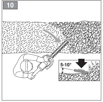
Proceed by cutting using curved movements from the bottom towards the top, keeping the blade as far from the body as possible (Fig. 10).
- Horizontal cutting
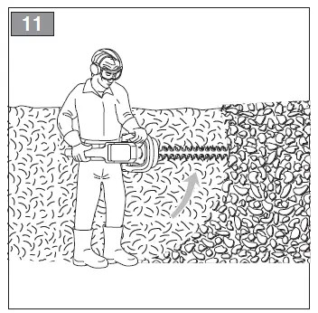
The best results will be obtained with the blade slightly inclined (5° – 10°) in the direction you are cutting, proceed with a curved movement, slowly and without interruptions, especially
in the case of very thick hedges (Fig.11).
6.4.3 Advice for operation
If the blades block while running or get caught up in the hedge branches:
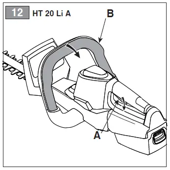
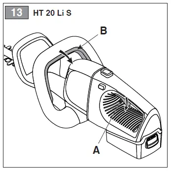
- Release the blade control lever (Fig. 12.A, Fig. 13.A) or the safety switch (Fig. 12.B, Fig. 13.B) immediately;
- Wait for the cutting means to come to a halt
- Remove the battery (para. 7.2.2)
- Remove the jammed material.
6.4.4 Lubricating the blades whilst working
If the cutting means overheats whilst working, it is necessary to lubricate the internal surfaces of the blades (para. 7.4).
This operation can only be done with the machine off and the battery removed from its housing.
6.5 STOP
- Release the blade control lever (Fig. A, Fig. 13.A) or the safety switch (Fig. 12.B, Fig. 13.B).
When you have stopped the machine, it will take a few seconds for the cutting means to stop.
Always stop the machine when moving between work areas.
Do not keep your hand on the safety switch when moving the machine to avoid accidentally starting the machine.
6.6 AFTER USE
- Remove the battery from its housing and recharge it (para. 2.2).
- When the cutting means has halted, fit the blade guard (Fig. 1.E).
- Allow the engine to cool before storing in an enclosed space.
- Clean (para. 3).
- Check there are no loose or damaged If necessary, replace the damaged components and tighten any screws and loose bolts or contact the authorised service centre.
- Check there are no damages to the If necessary contact the authorised service centre.
IMPORTANT Always remove the battery (para. 7.2.2) and fit the blade guard whenever the machine is unused or left unattended.
7. MAINTENANCE
7.1 GENERAL INFORMATION
IMPORTANT The safety standards to be followed are described in chapter. 2. Strictly comply with these instructions to avoid serious risks or dangers.
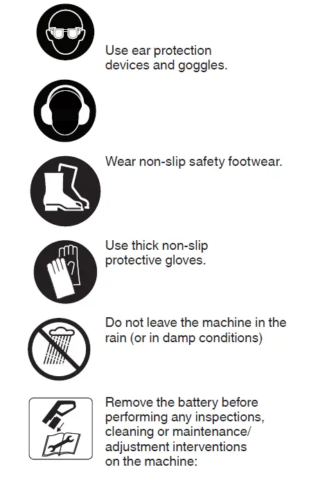
Before performing any inspections, cleaning or maintenance/adjustment interventions on the machine:
- Stop the machine
- Remove the battery from its housing and recharge it (para. 2.2) (never leave the battery inserted or within the reach of children or unauthorised persons)
- When the cutting means is stationary, apply the blade protection device, (except when working directly on the blade)
- Allow the engine to cool before storing in an enclosed space
- Use suitable clothing, protective gloves and goggles
- Read the relevant
IMPORTANT Any maintenance and adjustment operations not described in this manual must be carried out by your dealer or Authorised Service Centre.
7.2 BATTERY
7.2.1 Battery power reserve
Battery power reserve (and therefore the cuttable vegetation area before recharging is required) mainly depends on:
- Environmental factors, that cause higher energy requirements:
- cutting/trimming of very thick or wet hedges;
- cutting/trimming of bushes with branches that are too thick;
- operator behaviour that should be avoided:
- switching the machine on and off frequently whilst working;
- adopting a cutting technique that is unsuitable for the work to be performed (para. 4.1);
- cutting speed unsuitable for the condition of the hedge to be To optimise battery power reserve it is always recommended to
- cut the hedge when dry;
- set a cutting speed suitable for the condition of the shrubs;
- use the most appropriate technique for the work to be
If the need arises to use the machine for sessions which exceed the capability of a standard battery, it is possible to:
- purchase a second standard battery to immediately replace the discharged battery, without compromising
the continuity of operations;
- purchase a battery with an extended power reserve compared to the standard version (para. 1).
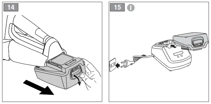
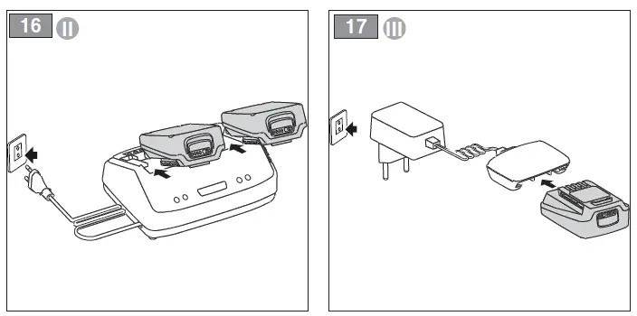
7.2.2 Battery removal and recharging (Fig.14÷17)
Fully charge the battery according to the instructions in the battery/battery charger booklet.
NOTE The battery is equipped with a guard that inhibits recharging if the environmental temperature is not between 0 and +45°C.
NOTE The battery can be recharged at any time, even partially, with no risk of damaging it.
7.3 CLEANING THE MACHINE
- To reduce fire hazards, keep the machine and, in particular, the motor free of leaves, branches or excessive
- Always clean the machine after use with a damp cloth dipped in neutral
- Remove all traces of humidity using a soft damp cloth. Humidity can generate risks of electric shocks.
- Do not use aggressive detergents or solvents to clean the plastic parts or hand
- Do not spray water onto the motor and electrical components and prevent them from getting
- To avoid overheating and damage to the motor or the battery, always keep the cooling air vents clean and free of
7.4 CLEANING AND LUBRICATION OF THE CUTTING MEANS
To increase the efficiency and working life of the blades, clean and lubricate them carefully after each work session:
Do not touch the cutting device until the battery has been removed and the cutting device is completely stationary.
- Place the machine in a stable horizontal position on the
- Use a soft cloth to clean the blades, along with a brush to remove more difficult dirt and debris.
- Lubricate the blades by applying a light layer of specific oil, preferably the non-pollutant type, along the upper edge of the
7.5 NUTS AND BOLTS
- Keep all nuts, bolts and screws tight to be sure the equipment is in safe working condition.
- Check regularly that the handles are fixed firmly.
7.6 CUTTING MEANS
Do not touch the cutting means until the battery has been removed and the cutting means is completely stationary.
7.6.1 Checks
Periodically check that the blades are not bent, damaged or deformed and that the screws are adequately tightened.
Adjustment of the distance between blades is not necessary, as this is predetermined by the manufacturer.
7.6.2 Sharpening
It is necessary to sharpen the blades when the trimming performance decreases and the branches tend to stick together.
For safety reasons, sharpening must be done by an Authorised Service Centre with suitable skills and equipment for the
job; without risking any damage to the blade which would make it unsafe when used.
Always replace and never repair a blade which has blunt cutting edges.
7.6.3 Replacement
The blade must never be repaired, but must be replaced as soon as signs of breaking, wearing, bending are noted or the sharpening limit is exceeded. For
safety reasons replacements must be performed by an Authorised Service Centre.
Blades displaying the code indicated on the Technical Data table should be used on this machine.
Given product evolution, the blades listed in the “Technical Data” table may be replaced in time with others having similar interchangeable and operating safety features.
8. STORAGE
IMPORTANT The safety regulations to follow for putting into storage are described in paragraph 2.4. Strictly comply with these instructions to avoid serious risks or hazards.
8.1 STORING
When the machine is to be stored away:
- Remove the battery from its housing and recharge it (para. 2.2)
- When the cutting means has halted, fit the blade guard
- Allow the engine to cool before storing in an enclosed space
- Clean (para. 3);
- Make sure there are no loose or damaged components. If necessary, replace any damaged components and tighten any screws and loose bolts or contact the authorised service centre;
- Store the machine:
- in a dry place;
- protected from inclement weather;
- in a place out of children’s reach;
- making sure that keys or tools used for maintenance are
9. HANDLING AND TRANSPORT
Whenever the machine is to be handled or transported you must:
- Stop the machine (para. 6.5);
- Make sure that all moving parts have come to a complete stop
- Remove the battery from its housing and recharge it (para. 2.2)
- Wear protective work gloves
- When the cutting means has
halted, fit the blade guard
- Only hold the machine using the hand grips and position the cutting means in the opposite direction to that used during operations
- Make sure that machine movements do not cause damage or injuries
10. ASSISTANCE AND REPAIRS
This manual provides all the necessary information to run the machine and for correct basic maintenance operations which can be performed by the user. Any regulations and maintenance operations not described herein must be carried out by your Dealer or Authorised Service Centre. Any operations performed in unauthorised centres or by unqualified persons will totally invalidate the Warranty and all obligations and responsibilities of the Manufacturer.
- Non-original parts and attachments are not approved; use of non-original spare parts and attachments will jeopardise the safety of the machine and relieve the
Manufacturer from all obligations or liabilities. - Original spare parts are supplied by authorised Dealers and by Authorised Service.
11. WARRANTY COVERAGE
The warranty conditions are intended for consumers only, i.e. non-professional operators.
The warranty covers all material quality and manufacturing defects recognised during the warranty period by your Dealer or Authorised Service Centre. The warranty is restricted.
to the repair or replacement of components recognised as faulty.
The warranty only applies to machines subjected to regular maintenance. The warranty does not cover damages resulting from:
- Failure to become familiar with the documentation accompanying the machine (Instruction manuals).
- Professional
- Carelessness,
- External causes (lightning, impact, presence of foreign bodies inside the machine) or
- Incorrect use or assembly are prohibited by the
- Poor
- Modification to the
- Use of non-genuine spare parts (adaptable parts).
- Use of accessories not supplied or approved by the
The warranty does not cover:
- The maintenance operations (described in the instruction manual).
- Normal wear and tear of
- Normal wear and
- Deterioration in the appearance of the machine due to
- Any ancillary expenses related to the enforcement of the warranty, such as costs incurred to travel to the user’s location, transfer of the machine to the Dealer, rental of
replacement equipment or calling of independent enterprises to perform maintenance work.
The user is protected by his or her own national legislation. The user’s rights under the national laws or his or her own country are not in any way restricted by this warranty.
12. TROUBLESHOOTING
| PROBLEM | PROBABLE CAUSE | SOLUTION |
| 1. Blade control lever and safety switch operated but the machine will not start (mod. HT 20 Li A)
or 2. Blade control lever, blade control locking button and safety switch operated but the machine will not start (mod. HT 20 Li S) |
Battery is not inserted or is inserted incorrectly | Make sure that the battery is inserted correctly (Fig. 6.A) |
| Low battery | Check the battery status and recharge if necessary (para. 7.2.2) | |
| Hedge trimmer is damaged. | Do not use the hedge trimmer. Remove the battery and contact an authorised service centre. | |
| 3. The motor shuts down whilst working | Battery is not inserted correctly | Make sure that the battery is inserted correctly (Fig. 6.A)) |
| Low battery | Check the battery status and recharge if necessary. (para. 7.2.2) | |
| 4. The cutting means is stationary when the blade control lever and safety switch are engaged (mod. HT 20 Li A)
or 5. The cutting means is stationary when the blade control lever, blade control locking button and safety switch are engaged (mod. HT 20 Li S) |
Hedge trimmer is damaged. | Do not use the hedge trimmer. Immediately turn off the machine remove the battery and Contact an Authorised Service Centre. |
| 6. The cutting means overheats whilst working | Insufficient blade lubrication | Turn off the machine, wait until the cutting means is stationary, remove the battery and lubricate the blades (para. 7.4) |
| PROBLEM | PROBABLE CAUSE | SOLUTION |
| 7. The cutting means comes into contact with a line or electric cable | – | DO NOT TOUCH THE BLADE AS IT MAY BE LIVE AND BE EXTREMELY
DANGEROUS! Grasp the machine using the insulated rear handgrip only and position it at a safe distance from yourself. Disconnect the current that powers the severed line or mains cable and remove the battery before freeing the blade teeth. |
| 8. The cutting means comes into contact with a foreign body. | – | Turn off the machine remove the battery and:
– Inspect for damage – Check for and tighten any loose parts – Contact an Authorised Service Centre for replacement or repair damaged parts with parts having equivalent specifications. |
| 9. Excessive noise and/or vibration is experienced whilst working | Loose or damaged parts | Turn off the machine remove the battery and:
– inspect for damage; – check for and tighten any loose parts; – Contact an Authorised Service Centre for replacement or repair damaged parts with parts having equivalent specifications. |
| 10. The machine gives off
smoke whilst working |
Hedge trimmer is damaged. | Do not use the hedge trimmer. Immediately turn off the machine remove the battery and Contact an Authorised Service Centre. |
| 11. Battery power reserve is low | Severe working conditions requiring greater
current absorption |
Optimise operations (para. 7.2.1) |
| Battery is insufficient for
operating requirements |
Use a second battery or an
extended battery (para. 13.1) |
|
| Decrease in battery capacity | Purchase a new battery | |
| 12. The battery charger is not recharging
the battery |
Battery is not correctly inserted in the battery charger | Check it is correctly inserted (para. 7.2.2) |
| Unsuitable environmental conditions | Recharge the battery in places with suitable temperatures (see battery/ battery charger instruction manual) | |
| Dirty contacts | Clean the contacts | |
| The battery charger is not energised | Check it is plugged in and the power socket is energised | |
| Faulty battery charger | Replace with an original spare part | |
| If the problem persists, refer to the battery/ battery charger manual |
If problems persist after implementing the solution, contact your Dealer.
13. ACCESSORIES ON REQUEST
13.1 BATTERIES
Different capacity batteries are available to suit specific operating requirements (Fig. 18). The list of approved batteries for this machine can be found in the “Technical Data” table
13.2 BATTERY CHARGER
Device used to recharge the battery (Fig.19).
]]>