Gardner Bender GDT-311 Digital Multimeter

METER FUNCTIONS

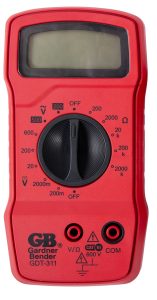
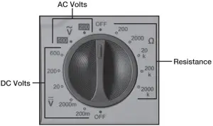
FUNCTIONS (Figure 1)
- 2000 count digital display
- 14 position
- AC Volts
- DC Volts 1
- Resistance
- Off Dial Selection
- Low Battery Indicator
- Common Input Jack
- Positive Input Jack
METER FUNCTIONS
| Meter Type: | Manual |
| Functions: | 3 |
| Ranges: | 12 |
| Display Count: | 2000 |
| Input Impedance: | 10 Meg Ohm |
| AC Volt Ranges: | 200 / 500 (2.5% + 5 digits) |
| DC Volt Ranges | 200m / 2000m / 20 / 200 / 600 ±(1.2% + 2 dgts) |
| Resistance Ranges: | 200 / 2000 / 20k / 200k / 2000k ±(1.5% + 2 dgts) |
| Operating Environment Indoor Use | |
| Operating Temperature: | 0°C – 40°C |
| Storage Temperature: | -10°C – 50°C |
| Relative Humidity: | 0% – 75%RH (0°C – 31°C) 0% – 50%RH (31°C – 40°C) |
| Altitude: | Up to 2000m |
| Ingress protection degree: | IP40 |
| Pollution degree: | 2 |
| Battery Type: | 9 Volt |
| Battery Life: | 100 hours with carbon-zinc cells, 200 hours with alkaline cells under normal conditions. |
| Over range Indication: | The three least significant digits are blank and the number “1” is displayed at the left when the range capacity is exceeded by the input. |
| Polarity Indication: | Negative displayed, positive implied |
| Size (LxWxH): | 5.51″ x 2.83″ x 1.26″ |
| Weight: | Approximately 110g (without batteries) |
| Test lead type: | ETL, cETL, CE, CAT III 600V 1A  |
| Agency Approvals: | ETL, CE, CAT III 600V |
Note: Accuracy is given for one year at 23°C ± 3°C rah<70%
READ FIRST: IMPORTANT SAFETY INFORMATION

 Read this operators manual thoroughly before using this multimeter. This manual is intended to provide basic information regarding this meter and to describe common test procedures which can be made with this unit. Many types of appliance, machinery, and other electrical circuit measurements are not addressed in this manual and should be handled by experienced service technicians.
The marking “  ” on the equipment represents Caution, risk of electric shock.
The marking “ ” on the equipment represents Caution, risk of danger.
The marking “  ” on the equipment represents Functional earth terminal.
The marking “ ” on the equipment represents Equipment protected by DOUBLE INSULATION or REINFORCED INSULATION
Use extreme caution when using this multimeter. Improper use of this meter can result in severe damage to property, severe personal injury or death. Follow all instructions and suggestions in this operators manual as well as observing normal electrical safety precautions. Do not use this meter if you are unfamiliar with electrical circuits and proper test procedures.
SAFETY WARNINGS
- This instruction manual contains warnings and safety rules which must be observed by the user to ensure safe operation of the instrument and retain it in safe condition.
- Read through and understand the instructions contained in this manual before using the instrument.
- Keep the manual at hand to enable quick reference whenever necessary.
- The instrument is to be used only in its intended applications.
- Understand and follow all the safety instructions contained in the manual.
- It is essential that all safety instructions are adhered to.
- Failure to follow the safety instructions may cause injury, instrument damage
The symbol indicated on the instrument means that the user must refer to the related parts in the manual for safe operation of the instrument. It is essential to read the instructions wherever the symbol appears in the manual.
| DANGER is reserved for conditions and actions that are likely to cause serious or fatal injury.WARNING is reserved for conditions and actions that can cause serious or fatal injury.CAUTION is reserved for conditions and actions that can cause injury or instrument damage. |
DANGER
- Never make measurement on a circuit in which voltage over 1000V exists.
- Do not exceed the CAT rating of the measuring device
- Do not attempt to make measurement in the presence of flammable gases.
- The use of the instrument may cause sparking, which can lead to an explosion.
- Never use the instrument if its surface or your hand is wet.
- Do not exceed the maximum allowable input of any measuring range.
- Never open the battery cover during a measurement.
- The instrument is to be used only in its intended applications or conditions. Use in other than as intended may cause instrument damage or serious personal injury.
WARNING
- Never attempt to make any measurement if any abnormal conditions are noted, such as broken case, cracked test leads and exposed metal part.
- Do not turn the function selector switch with plugged in test leads connected to the circuit under test.
- Do not install substitute parts or make any modification to the instrument.
- Return the instrument to your distributor for repair or recalibration.
- Do not try to replace the batteries if the surface of the instrument is wet.
- Always switch off the instrument before opening the battery compartment cover for battery replacement.
CAUTION
- Set the Function Switch to an appropriate position before starting measurement.
- Firmly insert the test lead
- Disconnect the test leads from the instrument for current measurement.
- Do not expose the instrument to the direct sun, high temperature and humidity or dewfall.
- Be sure to power off the instrument after use.
When the instrument will not be in use for a long period, place it in storage after removing the batteries. - Use only a soft cloth dampened with water or neutral detergent for cleaning the meter. Do not use abrasives, solvents or harsh chemicals. Allow to dry thoroughly before use.
OPERATING INSTRUCTIONS DIAL SETTINGS
AC VOLTS
There are two ranges for measuring AC voltage: 200 V and 500 V. For more accurate measurements under 200 volts, use the 200 Volt setting.
- Connect the black test lead to the “COM” terminal and the red test lead to the “V/” input terminal.
- Set the function/range switch to the appropriate AC V range. With AC Voltage, the polarity of the test leads is not a factor. NOTE: It is best to touch one of the test leads to ground or Neutral first and then touch the 2nd test lead to the hot wire.
- Touch the test leads to the circuit under test.
- Read the value of the measurement displayed.
- Typical AC Voltage measurements include wall outlets, appliance outlets, motors, light fixtures and switches.
DC VOLTS
There are five ranges for measuring DC voltage: 200m V, 2000m V, 20 V, 200 V, and 600 V. For more accurate measurements, use the lowest range possible without exceeding the value.
- Connect the black test lead to the “COM” terminal and red the test lead to the “V/” input terminal.
- Set the function/range switch to the appropriate DC V range.
- Touch the test leads to the circuit under test. Touch the black (common) test lead to the negative DC source first and red (positive) test lead to the “live” source second.
- Read the value of the measurement displayed. If the leads are reversed a ” ” indicator will appear on the display
- Typical DC Voltage measurements include car batteries, automotive switches and household batteries.
RESISTANCE
There are five ranges for measuring resistance 200, 2000, 20K, 200K and 2000K Ohms. For more accurate measurements use the lowest range possible without exceeding the value.
WARNING When measuring resistance always make sure the power is off.
- Connect the black test lead to the “
 ” terminal and red the test lead to the “V/” input terminal.
 - Set the function/range switch to the appropriate resistance (ohms) range.
- Touch the test leads to the resistor or non-energized component to be measured. Use the 2000K range when testing for resistance values in electronic components such as resistors and potentiometer. If the value of the component falls within the range of another setting, reset the function/range switch to that setting for a more accurate reading.
- Read the value of the measurement displayed. With resistance measurements, the polarity of the test leads is not a factor.
- Typical resistance/continuity measurements include resistors, potentiometer, switches, extension cords and fuses.
BATTERY REPLACEMENT
Note: When the battery’s voltage drops below the operating voltage, the mark “” will appear on the LCD to indicate the the batteries must be replaced. Caution: When changing the battery, disconnect the test leads from the circuit completely. Turn the meter off before removing the batteries.
- Remove the screws in the back cover of the tester and carefully separate the back cover from the front.
- Remove the battery from the contacts, noting the polarity of the battery terminals and contacts.
- Replace with one fresh 9 volt battery.
Note: Do not use rechargeable or lithium batteries in this unit. - Carefully replace the back cover and tighten the screws. Do not overtighten the screws as this may strip the threads in the tester housing.
One Year Warranty limited solely to repair or replacement; no warranty of merchantability or fitness for a particular purpose. Product is warrantied to be free of defects in materials and workmanship for the normal life of the product. In no event shall Gardner Bender be liable for incidental or consequential damage.
800.624.4320 · Milwaukee, WI 53209 · gardnerbender.com