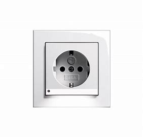
SCHUKO Socket Outlet with Voltage Overload Protection
Instruction Manual
Operating instructions
Safety instructions
Installation only by persons with appropriate electrotechnical knowledge and experience in the following areas:
- The “5 safety rules” to be observed are: disconnect; secure against reconnection; determine that no voltage is present; ground and short-circuit; cover or block off adjacent life parts
- Selection of suitable tools, measuring devices, and, if necessary, personal protective equipment
- Evaluation of the measurement results
- Selection of the electrical installation material to ensure the shutdown conditions
- IP degrees of protection
- Installation of the electrical installation material
- Type of mains supply (TN system, IT system, TT system) and the resulting connection requirements (classic earthing, protective earthing, necessary additional measures, etc.)
Improper installation endangers your own life and the lives of users of the electrical system and there is a risk of serious damage to property, e.g. through fire. You are at risk of personal liability for personal injury and damage to property.
Contact an electrical contractor!
Serious injuries, fire or property damage are possible. Please read and follow the manual fully.
To protect against high-energy surges, install multistage selective protection. Otherwise connected devices may be damaged.
These instructions are an integral part of the product and must remain with the end customer.
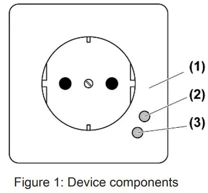
Device components

- Socket outlet
- Red light-emitting diode: protection function not in operation
- Red light-emitting diode: mains voltage present
Intended use
- Type 3 fine protection for protecting electrical and electronic devices against transient power surges according to EN 61643-11
- For use only in combination with Type 1 coarse protection and Type 2 medium protection
- For use in TN, TT and IT systems
- Stationary installation indoors in appliance box according to DIN 49073.
Instructions for operation
- The device protects electrical and electronic devices against transient power surges.
- Failure of the protection function is indicated by an acoustic and visual signal.
- Keep cables between loads (5) and surge protection socket outlet (1) as short as possible, max. 4 m.
- Do not lay protected cables parallel to unprotected cables. There is a danger of surge voltage coupling.
- When performing insulation measurements on the system, all surge protection products should always be disconnected, because otherwise the test voltage will be limited by the protective modules, thus leading to incorrect measurements.
Information for electrically skilled persons
Fitting and electrical connection
 DANGER!
The electrical shock when live parts are touched.
Electrical shocks can be fatal.
Before carrying out work on the device or load, disengage all the corresponding circuit breakers. Cover up live parts in the working environment.
Connecting and fitting the device

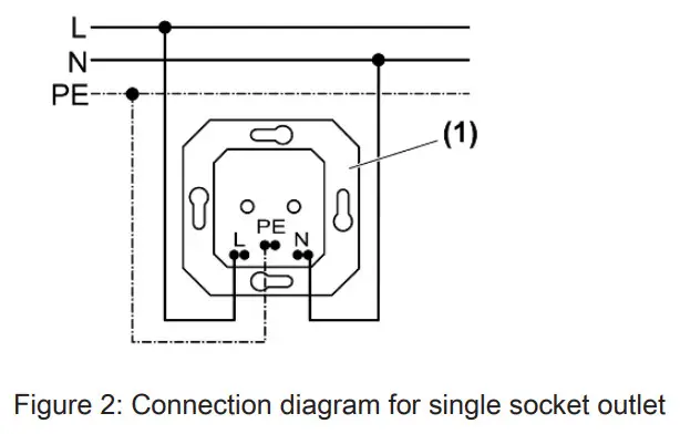
- Surge protection socket outlet
- Socket outlet with normal design
- Load
■ Connect surge protection socket-outlet according to the connection diagram for the single-socket outlet (Figure 2) or connection diagram for socket outlet combination (Figure 3).
 The maximum continuous voltage (see Technical data) must not be exceeded. In multiple combinations, when a surge protection socket outlet is used the other socket outlets used in the combination are also protected in the normal design. For this, the socket outlets have to be installed on the same conductor.
■ Install overvoltage protection socket outlet in appliance box.
■ Mount the cover and frame. Observe the correct installation position. Otherwise, the LED will not function.
Technical data
| Overvoltage protection | Type 3 arrester (one port) |
| Rated voltage AC | AC 230 V ~ (± 10%) |
| Mains frequency | 50 / 60 Hz |
| Maximum continuous voltage | AC 255 V~ (UC) |
| No-load voltage | 4 kV (UOC) |
| Rated load current | 16 A (IL) |
| Short circuit strength | 1.5 kA (ISCCR) |
| Protection level | |
| L/N | ≤ 1.25 kV (U) |
| L/PE; N/PE | ≤ 1.25 kV (U) |
| TOV characteristic | 442 V/5 s/120 min (UT) |
| Circuit breaker | max. 16 A (gG/C) |
| Ambient temperature | -5 … +40 °C |
| Relative humidity | 5 … 95 % (no moisture condensation) |
| Clampable conductor cross-section | 1.5 … 2.5 mm² |
![]() This device can protect connected loads only up to the protection level specified in the technical data. Surge voltages that are higher than that may still damage the connected devices. The same applies to devices that require a lower protection level. For this reason, we accept no liability for any damage to the connected loads.
This device can protect connected loads only up to the protection level specified in the technical data. Surge voltages that are higher than that may still damage the connected devices. The same applies to devices that require a lower protection level. For this reason, we accept no liability for any damage to the connected loads.
Troubleshooting
Acoustic signal sounds and red light-emitting diode lights up.
Overvoltage protection has failed due to high overvoltage. The socket-outlet continues to supply connected loads with mains voltage, but with no protection function.
Have the surge protection socket outlet exchanged by an electrically skilled person.
Pull the mains plug to cut off the acoustic signal. The signal tone will sound again when the plug is reinserted.
RCD protection switches trip.
The discharge of high overvoltages to earth by the overvoltage protection can cause RCD protection switches to trip.
Use RCD protection switches with a high peak withstand current.
Warranty
The warranty is provided in accordance with statutory requirements via the specialist trade.
Please submit or send faulty devices postage paid together with an error description to your responsible salesperson (specialist trade/installation company/electrical specialist trade). They will forward the devices to the Gira Service Center.
Gira
Giersiepen GmbH & Co. KG
Elektro-InstallationsSysteme
Industriegebiet Mermbach
Dahlienstraße
42477 Radevormwald
Postfach 12 20
42461 Radevormwald
Deutschland
Tel +49(0)21 95 – 602-0
Fax +49(0)21 95 – 602-191
www.gira.de
[email protected]